
Experimental and Numerical Study on Hydrodynamic Performance of Impermeable Comb-Type Breakwater
2012-12-13 02:56FANGZhuoZHANGNingchuanZANGZhipeng
船舶力学 2012年6期
FANG Zhuo,ZHANG Ning-chuan,ZANG Zhi-peng
(1 State Key Laboratory of Coastal and Offshore Engineering,Dalian University of Technology,Dalian 116024,China;2 Institute of Mechanics,Chinese Academy of Sciences,Beijing 100190,China)
1 Introduction
Comb-type breakwater is a new type of breakwater that is found to be efficient to reduce the wave reflection,the wave force and dissipate the incident wave energy compared with the traditional vertical wall breakwater.A type of permeable comb-type breakwaters has been successfully installed in Dayao Bay,Dalian[1].To investigate the hydrodynamic characteristics of comb-type breakwater,Niu et al[2-3]introduced the original purpose of developing the combtype breakwater and the experimental implementation plan of comb-type breakwater was proposed.Zhu et al[4]analyzed the mechanism and characteristic of the permeable comb-type breakwater and the shield effect of the permeable comb-type breakwater was also analyzed.Zhang et al[5]proceeded the structural analysis on side-plates according to the wave forces measured in experiments.The stress of side-plates was calculated and the reinforce design of side-plates was suggested.Hydrodynamic performances of comb-type breakwaters were stud-ied through physical model testing by Li et al[6]and Dong et al[7].Wave forces and wave reflections under both regular waves and irregular waves were studied.The empirical formulae for wave force reduction coefficient and wave reflection coefficient were proposed based on their experimental results.In their studies,limited dimension sizes of the structure under only one water level were considered.
While the studies mentioned above were almost exclusively based on model experiments with limited wave conditions and dimension sizes,there is still no numerical effort contributed to this issue.The hydrodynamic performance of the comb-type breakwater has not been studied adequately yet,especially the dangerous water level and mechanism of the wave force on the breakwater.
Compared with the permeable comb-type breakwater,the impermeable comb-type breakwater(shown in Fig.1)has been drawn much attention in the recent harbor construction for the purpose of ship berthing,because there is no wave transmission at the back-wave side of the breakwater.So the main purpose of this work is to investigate this impermeable comb-type breakwater under irregular waves by both experimental and numerical studies.The experimental setup is described in Section 2.The development of the 3-D numerical wave flume is described and validated in Section 3.In Section 4,the characteristics of wave pressure on the impermeable comb-type breakwater is firstly investigated by the experiments.Then the stress mechanism of the breakwater is analyzed by numerical techniques.Finally,the improved impermeable comb-type breakwaters with‘I’type baffle are proposed,the wave pressure characteristics and reflection coefficient of the improved structure are investigated.Conclusions are drawn in Section 5.

Fig.1 Sketch of an impermeable comb-type breakwater
2 Experimental setup
The experiments were conducted in the 69 m×2 m×1.8 m wave flume at the State Key Laboratory of Coastal and Offshore Engineering,Dalian University of Technology.The experimental setup is shown in Fig.2.The physical model is positioned at 25 m away from the wave maker.Three wave gauges are positioned in front of the structure to analyze the wave reflection coefficient of comb-type breakwater.The distance c should be at least 1.5 times of wave length in order to dissipate local disturbance,the interval of wave gauges a and b should not be the multiples of half wave length.Wave reflection coefficient is calculated by Goda two points method[8].Each test is repeated for three times.

Fig.2 Sketch of experimental setup
Fig.3 shows the original dimensions of one unit comb-type breakwater.According to the Froude Similarity Law and in consideration of the facilities available at the laboratory,a scale of 1:27 is adopted in the present study.The hydrodynamic characteristics of impermeable comb-type breakwater under irregular waves are investigated.JONSWAP spectrum is adopted to generate irregular waves.The experimental wave conditions are shown in Tab.1,the 1%wave height H1%ranges from 1.5 m to 3.5 m,and the extreme wave height is H1%=7.5 m.

Fig.3 The original dimensions of one unit comb-type breakwater

Tab.1 Experimental wave conditions
3 Numerical model
3.1 Governing equations and numerical techniques
The governing equations employed for the numerical wave flume are the Reynolds-Av-eraged Navier-Stokes(RANS)Equations.In RANS,turbulence flow could be regarded as the superposition of time-averaged flowand instantaneous fluctuation flow(ui′,p′),which could be expressed as Eq.(1).The governing equations can be written as Eqs.(2)and(3),and standard k-ε turbulence closure is used to close the model[9].

where i,j=1,2,3 for three-dimensional flows;ui=ith component of the velocity vector;ρ=density;p=pressure;gi=ith component of the gravitational acceleration;ν=kinematic viscosity coefficient;=Reynolds stress item.
This simulation is based on a CFD package Fluent.The VOF method is used to simulate the free surface,and tracking interface is accomplished by solving the continuity equation for the volume fraction[10].The mass source function method is applied to generate incident waves for the numerical wave flume[11-12].To generate waves using a mass source function,the Cartesian form of Eq.(2)in the source region is modified as follows:

Two opposite trains of surface gravity waves can be generated simultaneously from the source region.The source item in Eq.(4)is given by:

where s(x,y,z,t)=nonzero mass source function inside the source region;u(x,t)=horizontal velocity of wave particle;dx=mesh length along x direction.
The spongy layers are set on two sides of the wave flume to absorb the wave energy[13].In the spongy layers,the momentum source function μ(x)uicould be added to momentum equations(3).The coefficient μ(x)could be found in Troch and Rouch[14]and described in Eq.(6):

where x0is the start point of spongy layer;s is the length of spongy layer,which is about twice the length of the incident wave.
3.2 Validation of numerical model
3.2.1 Numerical wave tank
Irregular wave trains are generated by using the source wave generation method based on a known energy spectrum.The irregular wave is composed of a series of linear waves with different frequency,wave height,and so on.The source function employed to generate random wave trains is:

wheresηη(wi)=ithcomponent of spectrum value,component of angular frequency,εi=ithcomponent of random initial phase and d=water depth.
Five different wave trains with wave mode number(Nw)Nw=50,Nw=100,Nw=150,Nw=200 and Nw=250 were generated in the numerical wave flume,respectively.Wave period ranges between 0.5~2.2 s,the significant wave period is TP=1.39 s,the significant wave height is H1/3=0.038 m,and the water depth is d=0.523 m.Fig.4 shows the comparisons between the simulated wave spectrum and the target spectrum with different wave modes number,it can be seen that the results with wave modes number Nwranging from 150 to 250 are quite acceptable,although the wave spectrum with Nw=200 appears to agree better with the target spectrum than those with Nw=150 and Nw=250.The time history of simulated wave elevations with Nw=200 at location x=25.0 m is also analyzed,and the simulated significant wave period is TP=1.38 s and wave height is H1/3=0.040 m,the difference between the theoretical result and the simulated result is within 5%.Based on the comparison,Nw=200 is employed in simulating irregular waves in the following sections.

Fig.4 Comparisons between target spectra and simulated spectra with different wave modes
3.2.2 Wave pressure on a comb-type breakwater
The interaction between waves and an impermeable comb-type breakwater under three different random wave conditions is simulated in the 3-D wave tank,respectively.The numerical models are set up corresponding to the experimental conditions.The wave conditions and the numerical results are shown in Fig.5.The maximum wave pressure on side-plate PMis calculated for each case and compared to the experimental results.The numerical results agree well with the experimental results.
It can be seen from above validations that the present numerical wave flume is able to generate desired wave trains accurately,and the performance of the numerical wave flume in predicting wave forces is good.The numerical model is further applied to investigate the interactions between waves and the impermeable comb-type breakwaters in Subsection 4.2.

Fig.5 Comparison between experimental and numerical result of maximum wave pressure on side-plate
4 Results and discussions
4.1 Experimental results of wave pressure on the original comb-type breakwater
In this section,the hydrodynamic characteristics of the original impermeable comb-type breakwater shown in Fig.1 are studied.Totally 45 pressure transducers are distributed on the surface of the impermeable comb-type breakwater as shown in Fig.6.The distribution of the maximum wave pressure PMis analyzed under different incident waves.The experiments are carried out under seven different water levels of dw=-0.2 m,+0.44 m,+1.3 m,+2.3 m,+4.00 m,+4.30 m and+5.10 m.
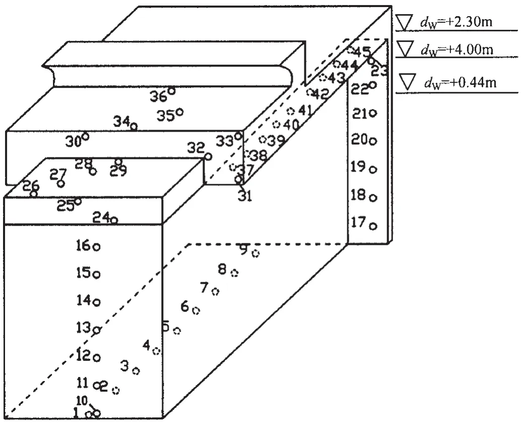
Fig.6 Distributions of pressure transducers on surface of impermeable comb-type breakwater
Fig.7(a)-(c)shows the maximum wave pressure distribution on different surfaces of the structure with dw=+0.44 m,+2.3 m+4.00 m,respectively.It can be concluded that,with the same water depth,the maximum wave pressure on each point generally increases with the in-crease of the wave height H1%.The maximum wave pressure on points No.1-16 and points No.24-36 is very low with the value ranging from 0 to 30 kPa.The maximum pressure at points No.17-23 increases sharply from the bottom to the top of the side-plate and reaches its peak value on ponit No.23 with a value of more than 100 kPa.The maximum pressure on the bottom face of the super-structure(No.37-45)increases from the front to the rear and the peak value appears near the points No.44 and No.45 with a value of more than 150 kPa.
Then the experiments are conducted under the extreme wave of H1%=7.5 with the above three water levels,respectively.The result is shown in Fig.7(d).It can be seen that the trend of pressure distribution on the structure is similar to that discussed above.The pressure on the side-plates and on the bottom of the super-structure is higher than that on other locations.The pressure with water level+0.44 m is higher than that with the other two water levels(+4.00 m and+5.10 m),with the peak value of over 250 kPa.

Fig.7 Maximum wave pressure on structure surface under different wave conditions
From the experimental results,it can be seen that the maximum pressure on the structure occurs mainly at two locations:the side-plates(surface 3)and the bottom face of the superstructure(surface 8).The pressure on points No.43-45 is higher than the pressure on other points on the bottom face of the super-structure.The pressure on points 22 and 23 on the side-plate is higher than that on other points on the side-plate.The maximum pressure on the side-plate is much larger than the designed bearing capacity.So it can be concluded that the most dangerous part of the comb-type breakwater is near the conjunction between the side-plate and the bottom of the super-structure.The dangerous water level for this structure ranges from+0.44 m to+2.3 m.
4.2 Numerical analysis on the mechanism of the wave pressure
The experimental results indicate that the top area of the side-plate suffers the impact wave pressure.This phenomenon was also simulated by the numerical model.As shown in Fig.8(a)and Fig.8(b),the time history of impact wave pressure on point 21 and point 23 of sideplate by the numerical model is compared with that of experimental result,respectively.The maximum impact wave pressure occurs on point 23 with a value of around 100 kPa.

Fig.8 Comparisons between experimental and numerical result of impact wave pressure on points of side-plate
Fig.9 shows the evolution of wave profiles during the impact wave attacking on the sideplate.Fig.10 shows the 2-D flow field around the side plate at the instant of impact wave occurring.

Fig.9 The 2-D wave profiles of impact wave acting on the breakwater
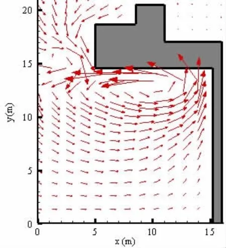
Fig.10 The 2-D velocity vector field of impact wave
For the dangerous water level,when waves propagate into the cavity and reach to the side-plate,the water is raised up and stranded temporarily in the rear of the cavity;then the water tends to escape out of the cavity in a reverse direction as shown in Fig.9(e).The space that was full of air originally is occupied by the rising water.At the same time,wave crests continue to advance to the side-plate,but the upper superstructure prevents the rising water dissipate effectively.So the mixture of air and wave appeared to become a large reversal vortex(Fig.10).In this process,the air can be divided into two parts:a portion of the air escapes along the bottom face of the superstructure in the opposite direction of wave propagation and the velocity vector of the air appears sharp shape and the velocity magnitude is obviously faster than that of the water.Further more,another portion of the air fails to escape and is trapped in the cavity by the waves.This is because that more air is carried into the cavity by the advancing wave and a few bumps also are formed between the water surface and the structure.These bumps block the air in the cavity from escaping,which leads to the impact wave pressure and the local stress concentration at he corner of the cavity.
It is understood from the structure design of the caisson that the high pressure zone occurs at the corner between the side plate and the bottom wall of the superstructure.The large water pressure was induced there because the superstructure prevented water from flowing upward when waves impacted the side plate.The above numerical analysis indicates that the special cavity composed of the superstructure and side-plate is the reason that causes the extreme impact wave pressure and the local stress concentration.In the following study,the superstructure between two caissons is removed to make a further verification of this assumption.The structure with the superstructure(structure 1)and the structure without the super-structure(structure 2)are shown in Fig.11.

Fig.11 Comb-type breakwater with and without superstructure between caissons
The wave pressure on the two structures is calculated with the water level dw=+0.44 m and the wave height H1%=2.0 m.When the side-plate is suffering the maximum wave force,the synchronous wave pressure on two separate caissons and two adjacent side-plates is shown in Fig.12(a)and 12(b),respectively.The x-axis in the figure denotes the width of the caisson and the two side-plates;the y-axis denotes the water depth.The contour lines of the wave pressure are in kPa.It can be observed that the wave pressure on structure 2 is apparently reduced from 100 kPa to 30kPa after being removed the superstructure.

Fig.12 Maximum wave pressure on structure 1 and structure 2 when dw=+0.44 m,H1%=2.0 m
4.3 An improved structure
In order to find an effective structure design to reduce the maximum wave pressure on the side-plate in the cavity,a few types of improved structures were proposed and analyzed.Finally the impermeable comb-type breakwater with‘I’type baffle(shown in Fig.13)was found to be the most efficient one among those proposed structures.In the following part,the hydrodynamic performance of this improved structure with‘I’type baffle is discussed.The experiments were carried out under the water level from+0.44 m to+5.1 m and the incident wave height H1%ranges from 2.0 m to 3.5 m.
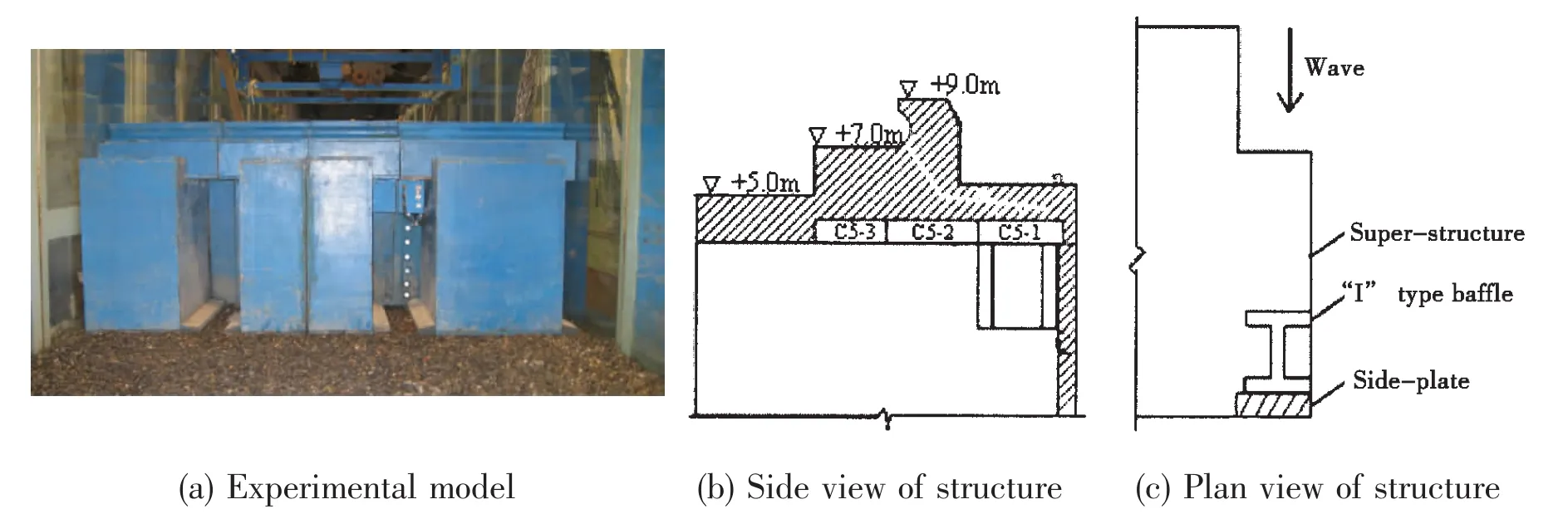
Fig.13 Sketch of improved structure with‘I’type baffle


Fig.14 Relationship of maximum wave pressure and relative wave height

Fig.15 The relationship between reflection coefficient and water level
4.3.1 Relationship between wave pressure and H1%/d
In the experiments,9 pressure transducers(No.1-9)are distributed evenly on the sideplate of the improved structure from bottom to top as shown in Fig.13(a).The relationship between relative wave height H1%/d and maximum wave pressure on the side-plate is shown in Fig.14(a)-14(c).It can be concluded that,with a constant d/L,the maximum wave pressure increases with the increase of H1%/d on each point.In addition,the maximum wave pressure PMgenerally increases from the bottom to the top of the side-plate.The maximum wave pressure on side-plate of the improved structure is much less than that on the original structure,with the value of around 50 kPa.
4.3.2 Relationship between reflection coefficient and water level
The reflection coefficient KRis another important factor to appraise the effectiveness of the breakwater.The comb-type breakwater can absorb majority of the wave energy mainly because there exists a phase difference between the reflected wave from the side-plate and that from the front wall of the caisson.When the designed parameters are selected properly,the incident waves and the reflected wave will superimpose with a phase difference in front of the caisson.This can reduce the effect of the wave forces on the breakwater.The relationship between the reflection coefficients and the water level is obtained in the experiments and shown in Fig.15.It can be seen that the reflection coefficient is much dependent on the water level.The value of KRunder water level dw=+4.0 m is much larger than the values under other water levels.But the reflection coefficient does not vary too much with the change of the relative wave height H1%.
5 Conclusions
In this paper,the hydrodynamic characteristics of an impermeable comb-type breakwater and its proposed improved structure are investigated experimentally and numerically.Main conclusions can be drawn as follows:
(1)A 3-D numerical wave flume is set up to simulate the irregular wave.Through comparisons,the present numerical model could simulate numerical irregular wave well with 200 random wave modes.
(2)The hydrodynamic performance of an impermeable comb-type breakwater is investigated by experimental studies under irregular waves.The results show that the extreme high wave pressure on the top area of the side-plate under the dangerous water level is the main cause which seriously influences the safety of the structure.
(3)The interaction between this impermeable comb-type breakwater and the irregular waves is simulated by the 3-D numerical model.The existence of the special cavity composed of the superstructure and side-plate is the main cause of the excessive wave impact pressure and the local stress concentration on the side-plate.The mechanism of the impact wave force is analyzed by the numerical technique.
(4)An improved impermeable comb-type breakwater with‘I’type baffle was proposed to reduce the extreme high wave pressure on the side-plate.The maximum wave pressure and the wave reflection coefficient of the improved structure are studied.
[1]Niu E Z,Wang Y W,Ma D T.Innovation of breakwater structures[J].Port&Waterway Engineering,2006,394(10):58-63.
[2]Niu E Z,Ma D T,Sun Z C.The novel comb-type breakwater[J].China Civil Engineering Journal,2003,36(10):51-55.
[3]Niu E Z,Deng L,Ma D T.Experimental studies and construction of comb-type breakwater[J].China Harbour Engineering,2001,6:5-8.
[4]Zhu H,Niu E Z,Zheng T L.Mechanism&characteristics of comb-type permeable breakwater and its sheltering effect[J].Port&Waterway Engineering,2001,333(10):31-34.
[5]Zhang T,Wang Q X,Zhao G F.Research of design theory for flange plate of comb-type caisson[J].The Ocean Engineering,2002,20(1):13-17.
[6]Li Y C,Sun Z C,Xu S Q.The hydraulic performance of comb-type vertical breakwater[J].Journal of Hydrodynamics,Ser.A,2002,17(4):472-482.
[7]Dong G H,Li Y C,Sun Z C.Interaction between waves and a comb-type breakwater[J].China Ocean Engineering,2003,17(4):517-526.
[8]Goda Y,Suzuki Y.Estimation of incident and reflected waves in random wave experiments[C]//Proceeding of 15th International Conference on Coastal Engineering.New York,ASCE,1976:828-845.
[9]Wang R J,Zhang K,Wang G.The technical bases and application examples of Fluent[M].Beijing:Tsinghua University Press.2007.
[10]Zhang C X,Wang G Y,Wang Y X.Study on the performances of air curtain breakwater by numerical simulation[J].Journal of Hydrodynamics,Ser.A,2009,24(5):543-549.
[11]Lin P Z,Liu P L F.Internal wave-maker for Navier-Stokes equations models[J].Journal of Waterway,Port,Coastal,and Ocean Engineering,1999,125(4):207-215.
[12]Li S Z.Study on 2-D numerical wave tank based on the software fluent[D].Harbin:Harbin Institute of Technology,2006.
[13]Li L,Lin Z W,You Y X.The numerical wave flume of the viscous fluid based on the momentum source method[J].Journal of Hydrodynamics,Ser.A,2007,22(1):76-82.
[14]Troch P,Rouch J D.Development of two-directional numerical wave flume for wave interaction with rubble mound breakwater[C].Proceedings of 26th Conference on Coastal Engineering,1998:1638-1649.
- 船舶力学的其它文章
- Steady Interaction Numerical Simulation of Cavitating Turbulent Flow between Ship Hull and Propeller
- Numerical and Model Test Study on the Hydrodynamic Performance of FDPSO with Spreading Mooring System
- A Simple and Efficient Method for the Coupled Motions of Multiple Bodies
- A Variational Method for the Homogenous State-vector Equation of Thermoelastic Bodies
- Discussion of Some Important Parameters in Fatigue Loading Calculation for Ship Structural Design
- Dynamic Optimization of Ship Grillages based on Grillage Dynamic Stiffness Algorithm and Scheme Database