环境友好型 AZ31B镁合金交流微弧氧化的表征
LU J H*, YIN X J, TAN A L K, KONG L T, CHENG Z L
环境友好型 AZ31B镁合金交流微弧氧化的表征
LU J H*, YIN X J, TAN A L K, KONG L T, CHENG Z L
研究了一种新的AZ31B镁合金交流电微弧氧化(MAO)工艺,采用了对环境更加友好的含硅酸盐的稀碱溶液作为电解质。结果发现氧化过程分为2个阶段,膜厚与微弧氧化时间呈抛物线关系。形貌观察表明,微弧氧化膜由一个致密层和一个多孔层组成。致密层的厚度约占整个膜厚的40%,膜表面的20%均匀分布着直径1 ~ 3 μm的孔。动电位极化测量显示,该新型微弧氧化膜的耐蚀性有明显提高,腐蚀电流降低了2个数量级,而自腐蚀电位正移了0.07 V。盐雾试验结果同样证实微弧氧化膜的耐蚀性有大幅度提高。
镁合金;微弧氧化;交流电;表征;耐蚀性
1 Introduction
Magnesium and its alloys have excellent physical and mechanical properties for a number of applications. In particular its high strength-to-weight ratio makes it an ideal metal for automotive and aerospace applications, where weight reduction is of significant concern[1-7]. Unfortunately, magnesium has an extremely negative equilibrium potential and poor corrosion resistance[8-9]. Anodizing is often used for the surface treatment of magnesium alloys to improve their surface properties. Current processes, such as DOW 17 and HAE, contain harmful ions in electrolytes such as Cr and/or F[10-12]. A new anodizing method known as micro-arc oxidation (MAO) has been developed which employs more environmentally friendly electrolytes. It was found that MAO treatment remarkably enhances surface properties of metals, such as corrosion resistance, hardness, wear resistance, and adhesion strength with the substrate in comparison with general anodizing treatments[13-14]. In modern oxidation technology, alternating current (AC) can offer better control over plasma chemical processes compared to direct current (DC) regimes[15].
In this paper, an environmentally friendly alkaline electrolyte was employed. Alternating current condition as well as the optical and structural characterization of the coating were viewed.
2 Experimental
2. 1 Materials
The materials were rolled magnesium alloy plates of AZ31B. Table 1 presents their chemical compositions.

Table 1 Chemical compositions of AZ31B magnesium alloys表1 AZ31B镁合金的化学成分(以质量分数表示)
The AZ31B magnesium alloy was cut into pieces as experimental samples. Machined specimens were ground with various grades of silicon carbide papers starting from 300 to 1200 grade, washed with deionized (DI) water and acetone.
2. 2 Preparation of film
MAO process under AC condition was carried out at a constant voltage with a sine waveform using a 50 A/200 V power supply. The electrolyte, comprising 5 g/L Na2SiO3, 5 g/L KOH, and organic amine, was prepared from DI water.
2. 3 Evaluations of film
The surface and cross-section morphologies, as well as the composition of MAO coatings were observed by a JSM-6360LV SEM equipped with atom force microscope (AFM). The thickness of MAO coatings was detected by L2003A metallurgical microscope. For potentiodynamic measurements, an Auto Lab Electrochemical System was used. A conventional three-electrode cell is used with the samples as WE, a Pt plate as AE and an Ag/AgCl electrode as RE. The electrolyte employed is a 3.5% NaCl solution. Scan rate is 1 mV/s, from −200 mV to +200 mV with respect to the OCP. A HL-90-BS tester is used to salt spray testing according to ISO 9227.
3 Results and discussion
3. 1 Current–time and thickness–time responses
In the MAO process, the voltage was adjusted linearly from 0 V to 190 V under a slope of 1.6 V/s during the development of barrier film with visible sparking commencing at 165 V. Intensive gas evolution could be seen on Mg surface as the current rises sharply. As shown in the current–time/ thickness–time curve in Figure 1, the current reached the maximum value of 1.2 A within 2 min. Two stages of anodizing could be distinguished from the graph. For the first stage, a primary film was created and generated very quickly within 5 min. After 5 min cell ampere reached stability with less sparks, a thick porous layer was formed and the growth became stable.
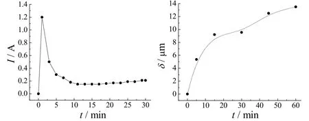
Figure 1 Variation of current density and film thickness with treatment time when anodizing on AZ31B magnesium alloy图1 在AZ31B镁合金上阳极化时电流密度与膜厚随处理时间的变化
With the increasing voltage in the first stage, magnesium surface reacted with the electrode solution and lost its metallic brightness. This conversion process lasted for 10 s. In a minute, a thin transparent passive film was formed on alloy surface. Under the dynamic model, relation between thickness and reaction time is of parabolic dependence, different from some research results showing linear growth[12,16].
3. 2 Morphologies and composition of MAO film and composite coatings
The MAO film appears slightly grey, relatively smooth, uniform and ceramic texture. The cross-sectional morphologies of MAO films formed in electrolytes containing potassium hydroxide and sodium silicate were observed using digital microscopy (shown in Figure 2). Obviously, the film is divided into two parts. A compact layer above the substrate, also named the first layer, occupies approximately 40% of total film. The compact layer is very important because the corrosion resistance of MAO film mainly depends on the thickness of compact layer. The porous outer layer plays as a mechanical protection.
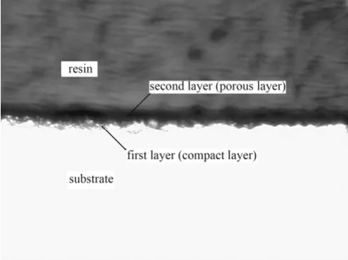
Figure 2 Cross-sectional morphology of MAO coating (×400)图2 微弧氧化膜的截面形貌(放大400倍)
The typical SEM morphologies of anodic film on AZ31B are shown in Figure 3. The 1-3 µm pores are evenly distributed and cover about 20% of film. From Figure 3b, several craters are clearly observed as if volcanic eruptions which should be associated with melting and cool crystallizing under high voltage and temperature. Due to high thermal stresses caused by plasma discharge, cracking of the surface layer can be observed around many craters[17]. The diameter of pores is approximately 4-40 µm which is smaller than other research results[14,18]. The reason may be that lower current density and low electrolyte concentration reduce the extent of the reaction, furthermore, negative part ( jn/jp= 1) of 50 Hz can give adequate cooling as sine waveform.
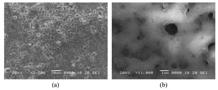
Figure 3 SEM observation for anodic film on AZ31B for 30 min图3 处理30 min后在AZ31B上所得阳极化膜的扫描电镜观察结果
The microstructures of the anodized coatings are clearer as shown via AFM in Figure 4. The AFM pictures also confirm SEM results basically. It shows that the average size of craters is also 1-3 µm, the depth of craters is approximately 0.5-1.5 µm, film roughness is ±0.15 µm and rather uniform. These data indicate both reaction and spark in given condition are relatively mild, and in anodizing process, only occasional tiny sparking was observed in this stage after 5 min.

Figure 4 AFM image showing misconstruction and size图4 微观结构及尺寸的原子力显微镜照片
3. 3 Electrochemical behavior
The potential–current curve in Figure 5 shows that there is obvious improvement in the corrosion resistance from MAO film compared to that of the bare magnesium alloy. The corrosion current density (jcorr) of MAO specimen is 59.9 nA/cm2whereas the jcorrof untreated sample is 5.47 µA/cm2; its Icorrwas reduced by two magnitude orders. Ccorrosion resistance (Rp) can be calculated based on the Stern-Geary equation[19].

Where βcand βarefer to Tafel constants for the cathodic and anodic reactions respectively. The relevant electrochemical parameters and corrosion resistance results in 3.5% NaCl solution are also listed in Table 2.
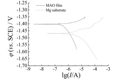
Figure 5 Polarization curves for AZ31B magnesium alloy with and without MAO treatment图5 AZ31B镁合金微弧氧化处理前后的极化曲线

Table 2 Electrochemical parameters of untreated magnesium alloy and MAO coating samples表2 未处理镁合金及微弧氧化膜试样的电化学参数
The corrosion rate of MAO coating was generally determined by Icorrand Rp. As can be seen in Table 2. It is obvious that the sample treated by MAO has better resistance than the untreated sample. The free corrosion potential is about −1.40 V for MAO specimen. On the other hand, the untreated samples show a free corrosion potential of −1.47 V. The positive shift of the corrosion potential of the sample with MAO film is approximately 0.07 V, giving the film better corrosion resistance than bare substrate.
3. 4 Anti-corrosion behavior for salt spray testing
The results of salt spray testing are displayed in Table 3. The results show that the micro-arc oxidation films formed in electrolytes containing potassium hydroxide and sodium silicate has excellent corrosion resistance and has passed 300-hour test. The ratio of loss weight is the lowest at 190 V for 60 min. Corrosion is also not apparent on both sides of the specimen. Its ratio of loss weight is only 0.021% and protection rating achieves grade 9.
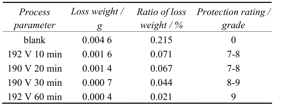
Table 3 Ratios of weight loss and protection rating for AZ31B and MAO films subjected to salt spray test表3 AZ31B及微弧氧化膜经盐雾试验后的失重率及保护等级
4 Conclusion
(1) During MAO of AZ31B, sparkling was visible starting from 165 V. As the current rose sharply, the anodizing current reached its maximum in 2 min. Two stages of anodizing could be distinguished from the process. The relation between film thickness and anodizing time is of parabolic dependence.
(2) The slightly grey surface coating of MAO is smooth, uniform and of ceramic texture. MAO film is consisted of compact (ca.40% of total film) and porous layer. The average pore size is smaller and in the range of 1-3 µm. The depth of crater is about 0.5-1.5 µm and film roughness is ±0.15 µm.
(3) It shows that new coating displays obvious improvement in the corrosion by potential–dynamic polarization tests. The corrosion current reduces by two orders of magnitude, and free corrosion potential shifts by 0.07 V positively.
(4) The results for salt spray testing also indicate that corrosion resistance of MAO had been promoted largely.
Acknowledgements
Support for this work was provided by Singapore Ministry of Education (Grant no. MOE2010-IF-1-027).
[1] YANG Z, LI J P, ZHANG J X, et al. Review on research and development of magnesium alloys [J]. Acta Metallurgica Sinica (English Letters), 2008, 21 (5): 313-328.
[2] CHOI J, NAKAO S, KIM J, et al. Corrosion protection of DLC coatings on magnesium alloy [J]. Diamond and Related Materials, 2007, 16 (4/7): 1361-1364.
[3] YABUKI A, SAKAI M. Anodic films formed on magnesium in organic, silicate-containing electrolytes [J]. Corrosion Science, 2009, 51 (4): 793-798.
[4] GHASEMI A, RAJA V S, BLAWERT C, et al. Study of the structure and corrosion behavior of PEO coatings on AM50 magnesium alloy by electrochemical impedance spectroscopy [J]. Surface and Coatings Technology, 2008, 202 (15): 3513-3518.
[5] SUN D X, SUN D Q, LI J B, et al. Research progress and application of welding technology of magnesium alloys [J]. Materials Review, 2006, 20 (8): 122-126.
[6] REINERS G, GRIEPENTROG M. Hard coatings on magnesium alloys by sputter deposition using a pulsed d.c. bias voltage [J]. Surface and Coatings Technology, 1995, 76/77: 809-814.
[7] ARDELEAN H, FRATEUR I, MARCUS P. Corrosion protection of magnesium alloys by cerium, zirconium and niobium-based conversion coatings [J]. Corrosion Science, 2008, 50 (7): 1907-1918.
[8] SHANG W, CHEN B Z, SHI X C, et al. Electrochemical corrosion behavior of composite MAO/sol–gel coatings on magnesium alloy AZ91D using combined micro-arc oxidation and sol–gel technique [J]. Journal of Alloys and Compounds, 2009, 474 (1/2): 541-545.
[9] CHAI L Y, YU X, YANG Z H, et al. Anodizing of magnesium alloy AZ31 in alkaline solutions with silicate under continuous sparking [J]. Corrosion Science, 2008, 50 (12): 3274-3279.
[10] LUO S L, DAI L, ZHOU H H, et al. New anodizing process for magnesium alloys [J]. Journal of Central South University of Technology (English Edition), 2006, 13 (2): 141-145.
[11] KURZE P. Corrosion and Corrosion Protection of Magnesium [M] // KAINER K U. Magnesium—Alloys and Technology. Weinheim: Wiley-VCH Verlag GmbH amp; Co. KGaA, 2003.
[12] GUO H F, AN M Z. Growth of ceramic coatings on AZ91D magnesium alloys by micro-arc oxidation in aluminate–fluoride solutions and evaluation of corrosion resistance [J]. Applied Surface Science, 2005, 246 (1/3): 229-238.
[13] ZHANG R F, ZHANG S F. Formation of micro-arc oxidation coatings on AZ91HP magnesium alloys [J]. Corrosion Science, 2009, 51 (12): 2820-2825.
[14] ARRABAL R, MATYKINA E, HASHIMOTO T, et al. Characterization of AC PEO coatings on magnesium alloys [J]. Surface and Coatings Technology, 2009, 203 (16): 2207-2220.
[15] XIN S G, SONG L X, ZHAO R G, et al. Influence of cathodic current on composition, structure and properties of Al2O3coatings on aluminum alloy prepared by micro-arc oxidation process [J]. Thin Solid Films, 2006, 515 (1): 326-332.
[16] WANG Y H, WANG J, ZHANG J B. Influences of current density on the properties of micro-arc oxidation coatings on AZ91D Mg alloy [J]. Journal of Chinese Society for Corrosion and Protection, 2005, 25 (6): 332-335.
[17] BLAWERT C, HEITMANN V, DIETZEL W, et al. Influence of process parameters on the corrosion properties of electrolytic conversion plasma coated magnesium alloys [J]. Surface and Coatings Technology, 2005, 200 (1/4): 68-72.
[18] ARRABAL R, MATYKINA E, VIEJO F, et al. Corrosion resistance of WE43 and AZ91D magnesium alloys with phosphate PEO coatings [J]. Corrosion Science, 2008, 50 (6): 1744-1752.
[19] FONTANA M G. Corrosion Engineering [M]. New York: McGraw-Hill Book Company, 1986: 196-197.
Characterization of environmentally friendly micro-arc oxidation of AZ31B magnesium alloy under alternating current
Lu Jianhong1,*, Yin Xijiang1, Annie Tan Lai Kuan2, Kong Ling Teck2, Cheng Zuolian2
( 1.Advanced Materials Technology Centre, Singapore Polytechnic, 500 Dover Road Singapore 139651, Singapore; 2.School of Chemical and Life Sciences, Singapore Polytechnic, 500 Dover Road Singapore 139651, Singapore )
A new micro-arc oxidation (MAO) process for AZ31B magnesium alloy, based on a more environmentally friendly electrolyte solution consisting of diluted alkaline solution with silicate under alternating current, was investigated. The findings show that oxidation behavior can be divided into two stages. The relation between film thickness and anodizing time is of parabolic dependence. The morphological views indicate that the film consists of a compact layer and a porous layer. The compact layer thickness is approximately 40%, and the 1-3 µm pores are evenly distributed with a coverage of about 20% of the film. It is shown that new coating displays obvious improvement in the corrosion resistance by potentiodynamic polarization tests. The corrosion current is reduced by two orders of magnitude, and free corrosion potential shifts positively by 0.07 V. The results for salt spray testing also indicate that the corrosion resistance of MAO are promoted largely.
magnesium alloy; micro-arc oxidation; alternating current; characterization; corrosion resistance
TG178
A
1004 – 227X (2012) 09 – 0021 – 04
date:2011–11–05 Revised date: 2012–03–19
Lu Jianhong, (E-mail) lujh@sp.edu.sg.
Biography:Lu Jianhong (1972–), Research Engineer, MEng(Engineering), Principal Investigator of magnesium project of Singapore Ministry of Education (Grant no. MOE2010-IF-1-027). Main fields of his scientific activities—studying of functional coating and advanced light weight materials.
[ 编辑:温靖邦 ]

