THREE-DIMENSIONAL NUMERICAL SIMULATION OF WAVE SLAMMING ON AN OPEN STRUCTURE*
DING Zhao-qiang, WANG Guo-yu, REN Bing
State Key Laboratory of Coastal and Offshore Engineering, Dalian University of Technology, Dalian 116024, China, E-mail: martindzq@126.com
(Received November 16, 2011, Revised January 16, 2012)
The three-dimensional numerical simulation of wave slamming on an open structure in the splash zone is carried out based upon the Volume Of Fluid (VOF) method. A wave basin is established by solving the continuity equation and the Navier-Stoke equations. The linear wave-maker is placed on the left side of the basin, and the numerical sponge layer and the SRC are placed on the right side of the basin to damp the incident waves. The three-dimensional wave slamming boundary condition is adopted to model waves in contact with and separated from the underside of the structure. The numerical results of wave slamming on a foursquare structure for various parametric cases are verified by the experimental results. Meanwhile, the characteristics of the wave impact forces on the undersides of the rectangular structures with various length-breadth ratios are discussed.
wave slamming, three-dimensional, Volume Of Fluid (VOF)
Introduction
The wave slamming has a significant influence on the safety of the superstructures located in the splash zone. The extreme wave impact forces caused by the strong wave slamming may cause tremendous damages of the superstructures of open structures. The wave slamming involves very complicated mechanisms because of its strong nonlinearity, the transient effect, the fluid viscosity, the turbulence and the miscibility of fluid and gas, etc..
A great number of investigations were carried out in order to characterize the wave slamming loads on the basis of the Morison’s equation and the Kaplan’s equations[1,2]. The Morison’s equation is widely applied in the design of offshore and coastal structures for structures relatively small compared with the wave length. The Kaplan’s equations were developed todetermine the wave impact forces on flat plate-like horizontal deck structures. Baarholm and Faltinsen[3]presented an approximate solution for the impact on a fixed horizontal deck similar to the Kaplan’s solution.
Laboratory experiments were carried out to estimate the wave impact loads, such as Baarholm[3], Ren and Wang[4,5], Zhou et al.[6], Lan et al.[7]and Jin and Meng[8]. Ren and Wang[9]developed numerical models based on the improved Volume Of Fluid (VOF) method to simulate the regular and random wave impact pressures. Kleefsman et al.[10]put forward an improved VOF method together with a local height function and discretized the equations on a fixed Cartesian grid using the finite volume method to study the uplift forces and the horizontal forces on the jacket type offshore platform. A boundary element method for the velocity potential due to impact was proposed by Baarholm and Faltinsen[11]. Li[12]established a non-reflecting irregular wave flume based on the VOF method and investigated the characteristics of the irregular wave slamming. Gao et al.[13]corrected the SPH method to model the wave slamming on the surface of structures.
The above mentioned are studies of two-dimensional wave slamming problems. For large volume structures, the three-dimensional effects on the wave impact should be included. Baarholm and Stansberg[14]obtained a three-dimensional solution for the vertical wave slamming force on the Deck of a Gravity-Based Structure (GBS) Platform based on the Kaplan’s approach. Scolan et al.[15]and Ding et al.[16]conducted an experimental investigation of oblique random wave slamming on a three-dimensional structure. Baarholm[17]carried out model tests to demonstrate that three-dimensional effects significantly reduce the wave-in-deck loads.
This paper establishes a three-dimensional wave basin based on the VOF method to investigate the characteristics of the wave impacting on the structures located in the splash zone. The numerical model is verified by the three-dimensional experimental results of wave impacting on a foursquare structure in various parametric cases. The characteristics of the wave impact forces on the undersides of the rectangular structures with various length-breadth ratios are discussed by using the present three-dimensional numerical model.

Fig.1 The three-dimensional numerical model
1. Governing equations
The continuity equation and the Navier-Stokes equations are used as the governing equations (in Cartesian coordinates as shown in Fig.1).
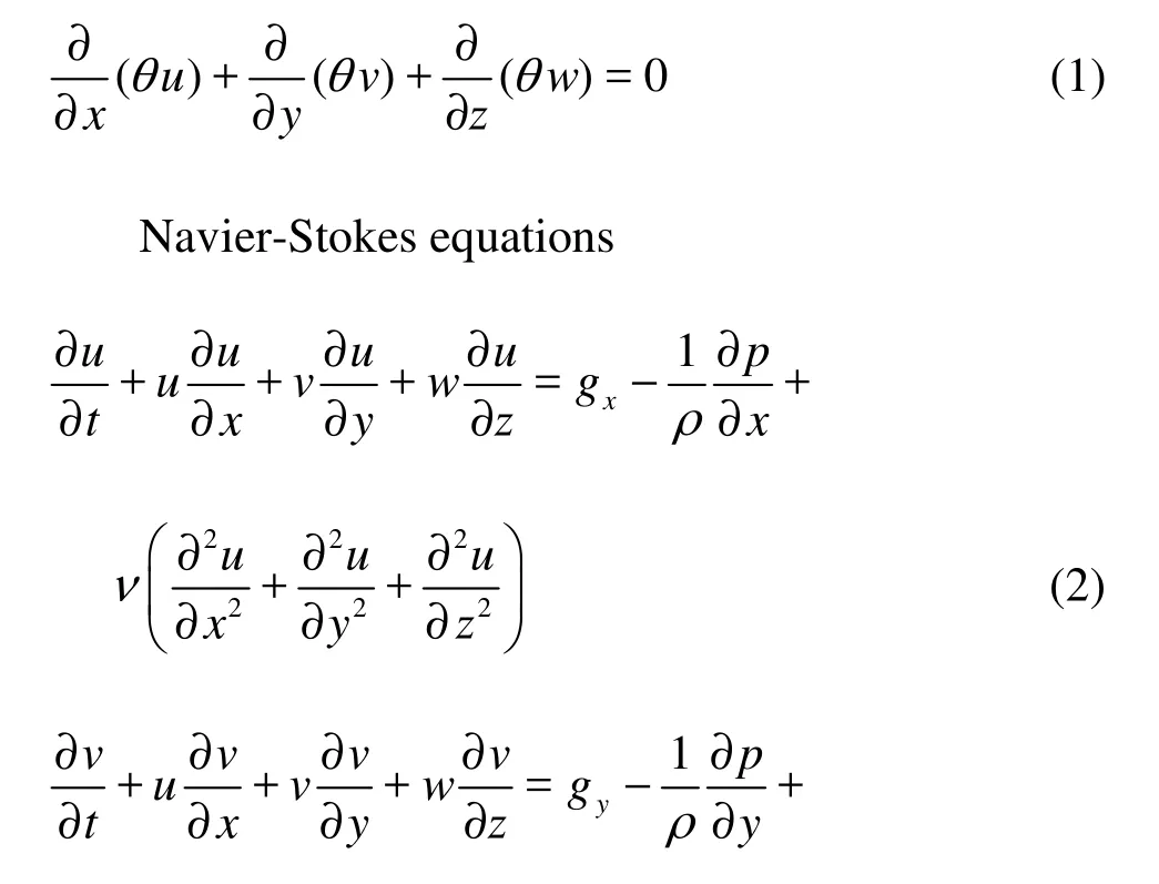
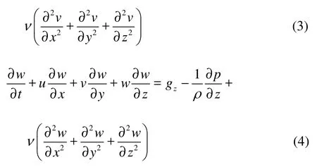
Continuity equation where u, v and w are the velocity components in x, y and z directions, respectively, p is the pressure, ρ is the fluid density, ν is the coefficient of kinematic viscosity. θ is the volume fraction of the partial cell.
The free surface is traced by the VOF method. The function F(x,y,z,t) is defined to be unity for the fluid cell and zero for the void cell. A free surface cell is defined as a cell with a non-zero value of F and having at least one neighboring cell with F of zero value. The time dependence of F is governed by Eq.(5).

The staggered cell and the finite difference approximation are used to discrete the governing equations[9].
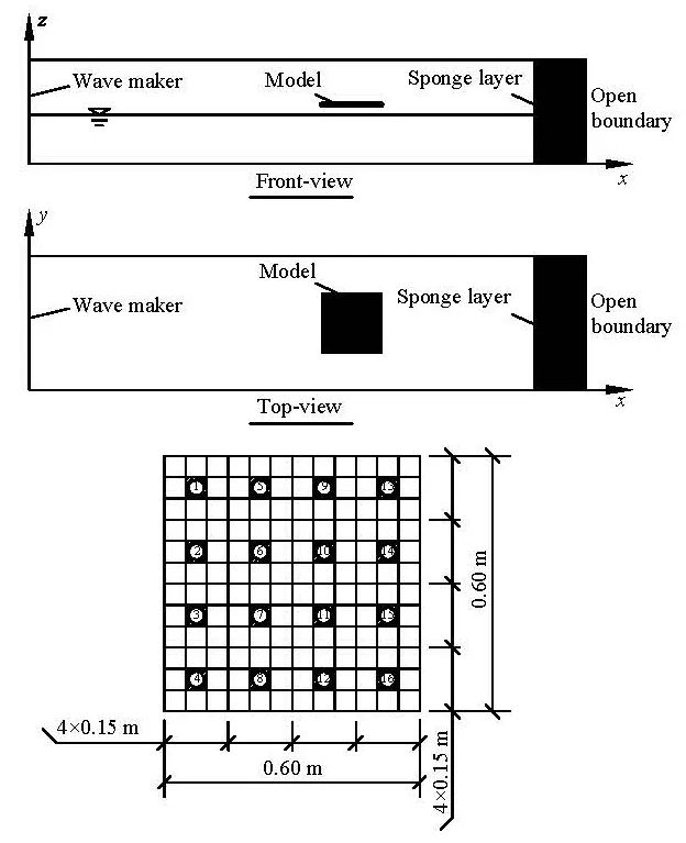
Fig.2 The computation domain and the structure model

Fig.3 The comparisons of the time series of the impact pressures (T=1.75s , H=0.1m , s/H=0.4)
2. Boundary conditions
2.1 Wave-making boundary
A wave maker of the sectional type is placed on the left side of the wave basin as shown in Fig.1. Based on the linear wave-making theory, the horizontal velocity of the thj wave maker paddle with the stroke of0A and the angular frequency ω is expressed as

The wave elevation η'at the distance x from the thj wave maker paddle is
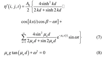
where k is the wave number, μnis the nth solution of Eq.(8). The first term of the right side is related with th e pro gre ssing wav es and t he seco nd term is relatedwiththedampingstandingwaves,whichwilldecay significantly at a certain distance from the wave paddle.

Fig.4 The comparison of the distribution of wave impact pressures (H=0.1m , s/H=0.3)
The wave elevation at the wave paddle where x(i)=0 (i=1) can be derived from Eq.(7) and written as

Then, the horizontal velocity of the thj wave maker paddle is

2.2 Sponge boundary
The sponge layer is introduced as the artificial damping to absorb the outgoing waves under the Sommerfeld Radiation Condition. The damping term is added to the Navier-Stokes equations. A function in the radical sign is chosen as the damping coefficient μ (x)[18], aswhere α is the empirical parameter,1x is the start coordinate of the sponger layer,2x is the ending coordinate of the sponger layer,lx is the length of the sponge layer, usually 1-2 times of the wave length.


2.3 Impact boundary
The contact-line boundary condition implemented in the VOF method is specified to model the wave in contact with and separated from the underside of the structure. When the wave approaches the underside of a structure but not in contact with it yet, the cell next to the structure is a free surface cell. As long as the initial contact occurs, the free surface disappears and the free surface cell becomes an internal fluid cell that satisfies the continuity condition.
Due to the free surface tracing requirement, the obstacle cell modeling the structure is defined as a void cell, which means that the cell with F of nonzero value beneath the obstacle is always a surface cell. Even though the water approaches the obstacle cell and the cell beneath the obstacle cell changes from the surface cell to the fluid cell with =1F, the VOF algorithm will correct the value of F to be slightly less than 1 to be a surface cell. That will result in an overflow of the simulation.
So the slamming conditions are set to consider the cell under the obstacle cell with F value slightly less than 1 as a fluid cell that is not a surface cell by considering the value of F(i,j,k) in the neighbor of the structure: if F is greater than Fcwhich is slightly less than 1, this cell is a fluid cell and the wave contacts with the obstacle cell. WithcF being in the range 0.95-0.99, the numerical results see little difference. SocF is selected as 0.96, to consider the air bubbles sealed in the water or the sloping surface. The slamming conditions are set by considering the value of F(i,j,k) in the neighbor of the structure as:

3. Validation of the numerical model
The numerical results of three-dimensional wave impacting on a foursquare structure in the splash zone are verified by the experimental results in various parametric cases as described in detail in Ren et al.[19]. The computation region is shown in Fig.2.
The numerical wave basin is 20 m long and 3 m wide, with the water depth of 0.5 m. A mesh of 400 cells in the x direction, 60 cells in the y direction and 30 cells in the z direction is used. The space increment is dx=0.05m in xdirection, dy= 0.05m in y direction, and dz=0.03m in z direction. The time step dt is adjustable according to the Courant number.
The wave-maker is placed on the left end and the sponge layer and the open boundary are placed on the right end. The water density ρ=1000kg/m3, the gravitational acceleration g=9.8m/s2, and the kinematic viscosity ν=1×10⁻⁶m2/s . The incident waves are perpendicular to the regular waves. The computing time is about 40 s. The structure is represented by the appropriate mesh cells of the same size as the experiment model. The side length B of the structure is 0.6 m. The shadow cells as shown in Fig.2 represent the sixteen transducers located on the underside of the experiment model.

Table 1 Computed and measured value of the maximum wave impact pressures
3.1 Impact pressures
3.1.1 Time series of impact pressures

Fig. 5 Comparisons of the time series of the wave impact force (T=1.75s )
The comparisons of the numerical results and the experimental results of the time series of wave impact pressures on four cells (pressure transducers) are shown in Fig.3, The incident wave height H=0.1m , the wav e period T=1.75s ( B/ L=0 .14 7) an d the relative clearance s/H=0.4.Itcanbeseenfrom Fig.3 that the computed wave impact pressures agree generally with those of the experimental results. The large peak pressure occurs at the initial contact and varies randomly from cycle to cycle even under the regular wave action. It is indicated that the slamming pressures have a considerable magnitude and take a much shorter rise time, followed by a slowly-varying pressure of a smaller magnitude, which varies from positive to negative, and then becomes zero.
3.1.2 Distribution of the impact pressures
The peak values of the impact pressures on each measuring point during the total computing time are selected and rearranged in the order from large to small values. In view of the stability and repeatability, the average value of the largest one-third peak pressures considered as the significant peak pressure is taken as the characteristic peak pressure at each measuring point, represented by,1/3lP. The maximum significant peak pressure at those measuring points is represented by,maxcP.
The distribution of the significant impact pressures on the underside of the structure for the wave height H=0.1m , the relative clearance s/H =0.3 and various wave periods are displayed in Fig.4. The abscissa represents the distance of the structure along the direction of the wave propagation. The ordinate represents the distance of the structure across the direction of the wave propagation. The curve in the figure is the contour line of the significant peak pressures on the structure. The arrow indicates the direction of thewave propagation. It can be seen from Fig.4 that the numerical results are in agreement with the experimental results. The contour lines of the significant peak pressures have symmetrical distributions with respect to the wave rays and the values of the pressures on the center parts of the structure are obviously larger than those on the surrounding parts.
The comparisons between the computed maximum peak pressures and the experimental results for some cases are listed in Table 1. According to Baarholm’s comparisons (2005), the maximum error between numerical and experimental results for the maximum upward directed force and the maximum downward directed force is 25%. It can be seen from Table 1, a good agreement is obtained between the numerical results and the experiments in general.
3.2 Impact forces
With the impact pressures of each cell (transducer) at one moment and the representing area of each measuring point, the wave impact force on the structure at this moment is calculated by integration. The peak values of the impact forces on the structure during the total sampling time are selected and rearranged in the order from large to small values. In view of the stability and repeatability, the average value of the largest one-third peak force values considered as the significant peak force is taken as the characteristic impact peak force on the structure, represented by F1/3.
Figure 5 shows the comparisons of the time series of the computed impact forces and the experimental results on the structure. The incident wave height =H0.075 m and 0.10 m, the wave period T=1.75s (B/L=0.147) and the relative clearance s/H=0.3 and 0.4. It can be seen from Fig.5 that the computed impact forces generally agree with those of the experimental results.
Figure 6 shows the comparisons of the wave impact force versus the relative structure width between the numerical results and experimental results. It can be seen from Fig.6 that the wave impact forces have two peak values against the relative structure width. The maximum peak value is at B/L=0.147, and the secondary peak value is at B/L=0.275, which agrees with the experimental results. It also can be seen that the numerical results are a little larger than the experimental results. The mechanism of the wave slamming is very complicated and involves a strong nonlinearity, the viscosity of the fluid, the instantaneous effect, and the mixed air, etc. The present numerical method can well deal with the strong nonlinearity, the viscosity of the fluid, and the instantaneous effect, but not the mixed air and other uncertain factors, which may explain the difference between numerical and experimental results.
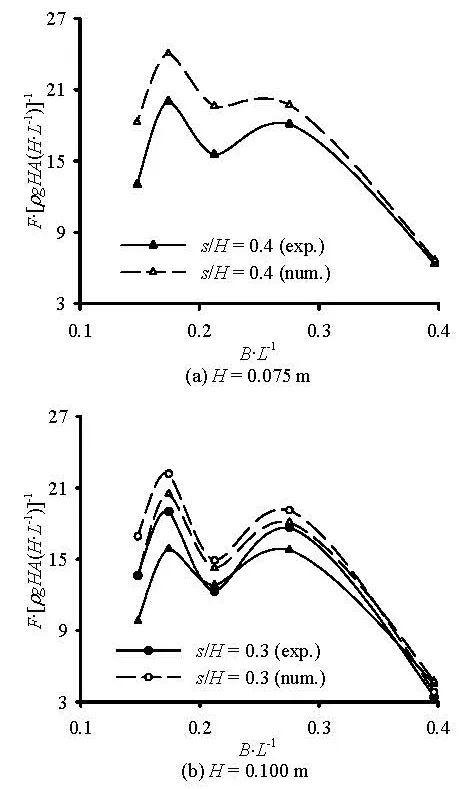
Fig. 6 Wave impact forces versus the relative structure width for the square structure
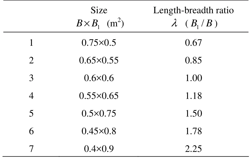
Table 2 Parameters of the structures with different length-breadth ratios
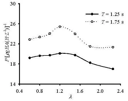
Fig.7 Wave impact forces versus the length-breadth ratio

Table 3 The dimensionless impact forces on the underside of the structures with different length-breadth ratios
4. Numerical results of rectangular structures
The present numerical model is used to study the three-dimensional wave slamming on the retangular structure. The computation region is shown as Fig.2. The numerical wave basin and the details of the mesh are the same as those in the validation model.
Table 2 shows the cases with different lengthbreadth ratios and the corresponding sizes of the structures with nearly the same area, where1B represents the length of the structure along the direction of the wave propagation, and B represents the length of the structure cross the direction of the wave propagation. The length-breadth ratio is defined as1=/Bλ B. The incident waves are perpendicular to the regular waves. The wave period T is chosen as 1 s, 1.25 s, 1.5 s, 1.75s and 2 s, the wave height is 0.075 m and the relative clearance /sH is 0.4.
Figure 7 shows the wave impact forces on the underside of the rectangular structure versus the length-breadth ratio, where the abscissa represents the length-breadth ratio of the structure λ, the ordinate represents the dimensionless wave impact forces /F [ρgHA(H/L)], and the corresponding values of the dimensionless impact forces are listed in the Table 3. It can be seen from Fig.7 and Table 3 that the wave impact forces on the undersides of the structures reach the crest value while the length-breadth ratio of the structure λ is equal to 1.18.
Figure 8 shows the wave impact forces on the underside of the structures versus the relative structure width where the wave height is 0.075 m and the relative clearance is 0.4. The ordinate represents the dimensionless wave impact forces F/[ρgHA(H/ L)]. It can be seen that the wave impact forces have two peak values versus the relative structure width. The maximum peak value is at B/L=0.147, and the secondary peak value is at B/L=0.275, which is the same as the results for the foursquare structures. maximum peak value is at B/L=0.147 and the secondary peak value is at B/L=0.275, which is the same as the results for the foursquare structure.
5. Conclusion
The three-dimensional numerical model based on Navier-Stokes equation and VOF method is built to study the wave slamming on open structures in the splash zone. The properties of time series of the computed wave impact pressures and forces on the foursquare structures are found to be reasonable in comparison with those of the experimental results. The distribution of the computed impact pressures on the structure agrees well with that of the measured results. The numerical values of the pressures and forces are a little larger than those of the experimental results due to the neglected factors in the numerical simulations, such as the air bubble, air cushion and other complicated factors that are difficult to model using the present numerical model. For the rectangle structures, the wave impact forces on the structure reach the crest value when the length-breadth ratio of the structure λ is equal to 1.18. And the impact forces have two peak values versus the relative structure width, the
[1] KAPLAN P. Wave impact force on offshore structures: re-examination and new interpretations[C]. Offshore Technology Conference. Houston, Texas, USA, 1992, 79-86.
[2] KAPLAN P., MURRAY J. J. and YU W. C. Theoretical analysis of wave impact forces on platform deck structures[C]. 14th International Conference on Offshore Mechanics and Arctic Engineering. Copenhagen, Denmark, 1995, 189-198.
[3] BAARHOLM R., FALTINSEN O. M. Experimental and theoretical studies of wave impact on an idealized platform deck[C]. 4th International Conference on Hydrodynamics (ICHD 2000). Yokohama, Japan, 2000.
[4] REN B., WANG Y. Spectral analysis of irre- gular wave impact on the structure in splash zone[C]. 21th International Conference on Offshore Mechanics and Arctic Engineering. Oslo, Norway, 2002, 149-154.
[5] REN B., WANG Y. Laboratory study of random wave slamming on a piled wharf with different shore connecting structures[J]. Coastal Engineering, 2005, 52(5): 463-471.
[6] ZHOU Yi-ren, CHEN Guo-ping and WANG Deng-ting. Calculation methods of uplift forces of waves on a horizontal plate[J]. The Ocean Engineering, 2004, 22(2): 26-30(in Chinese).
[7] LAN Ya-mei, GUO Wen-hua and LIU Hua. Experimental study on hydrodynamic loads on a horizontal slab and pile in regular wave[J]. Chinese Journal of Hydrodynamics, 2010, 25(4): 551-558(in Chinese).
[8] JIN J., MENG B. Computation of wave loads on the superstructures of coastal highway bridges[J]. Ocean Engineering, 2011, 38(17-18): 2185-2200.
[9] REN B., WANG Y. Numerical simulation of random wave slamming on the structure in the splash zone[J]. Ocean Engineering, 2004, 31(5-6): 547-560.
[10] KLEEFSMAN K. M., FEKKEN G. and VELDMAN E. P. et al. An improved volume-of-fluid method for wave impact problems[C]. The Fourteenth (2004) International Offshore and Polar Engineering Conference. Toulon, France, 2004, 334-341.
[11] BAARHOLM R., FALTINSEN O. M. Wave impact underneath horizontal decks[J]. Journal of Marine Science and Technology, 2004, 9(1): 1-13.
[12] LI Xue-lin. The study on the characteristics of flow field in the process of wave impact[D]. Ph. D. Thesis, Dalian: Dalian University of Technology, 2009(in Chinese).
[13] GAO R., REN B. and WANG G. et al. Numerical modelling of regular wave slamming on subface of open-piled structures with the SPH method[J]. Applied Ocean Research, 2012, 34: 173-186.
[14] BAARHOLM R., STANSBERG C. T. Extreme vertical impact on the deck of a Gravity-Based Structure (GBS) platform[C]. Rogue Waves 2004. Brest, France, 2004.
[15] SCOLAN Y. M., REMY F. and THIBAULT B. Impact of three-dimensional standing waves on a flat horizontal plate[C]. 21st International Workshop on Water Waves and Floating Bodies. Loughborough, UK, 2006.
[16] DING Z., REN B. and WANG Y. Experimental study of unidirectional irregular wave slamming on the threedimensional structure in the splash zone[J]. Ocean Engineering, 2008, 35(16): 1637-1646.
[17] BAARHOLM R. Experimental and theoretical study of three dimensional effects on vertical wave-in-deck forces[C]. 28th International Conference on Ocean, Offshore and Arctic Engineering. Honolulu, Hawaii, USA, 2009.
[18] LI Ben-xia, YU Yu-xiu and ZHANG Ning-chuan. Development of 2-D numerical random wave tank and its application[J]. Marine Science Bulletin, 23(5): 1-9(in Chinese).
[19] REN B., DING Z. and WANG Y. et al. Experimental study of unidirectional wave impact on the three-dimensional structure in the splash zone[C]. The Seventeenth (2007) International Offshore and Polar Engineering Conference. Lisbon, Portugal, 2007, 3623-3629.
10.1016/S1001-6058(11)60274-6
* Project supported by the National Natural Science Foundation of China (Grant No.51179030) and the National Basic Research Development Program of China (973 Program, Grant No. 2011CB013702).
Biography: DING Zhao-qiang (1982-), Male, Ph. D.
WANG Guo-yu,
E-mail: wanggyu@dlut.edu.cn
- 水动力学研究与进展 B辑的其它文章
- MODELING DAM-BREAK FLOOD OVER NATURAL RIVERS USING DISCONTINUOUS GALERKIN METHOD*
- TURBULENCE TRANSPORT OF SURFACTANT SOLUTION FLOW DURING DRAG REDUCTION DEGENERATION*
- NUMERICAL STUDIES ON LOCOMOTION PERFROMANCE OF FISHLIKE TAIL FINS*
- THEORETICAL AND EXPERIMENTAL STUDIES OF THE FLARING GATE PIER ON THE SURFACE SPILLWAY IN A HIGH-ARCH DAM*
- A NEW NUMERICAL WAVE FLUME COMBINING THE 0-1 TYPE BEM AND THE VOF METHOD*
- PIV EXPERIMENTAL RESEARCH OF FLOW STRUCTURE IN RECTANGULAR CHANNEL WITH TRANSVERSELY PLACED SPIRAL COIL INSERT*

