PIV EXPERIMENTAL RESEARCH OF FLOW STRUCTURE IN RECTANGULAR CHANNEL WITH TRANSVERSELY PLACED SPIRAL COIL INSERT*
TANG Yu-feng, TIAN Mao-cheng, ZHANG Guan-min
School of Energy Source and Power Engineering, Shandong University, Jinan 250061, China, E-mail: tyf-sdu@foxmail.com
(Received November 3, 2011, Revised February 28, 2012)
The flow field in a rectangular channel with a transversely placed spiral coil insert is investigated by Particle Image Velocimetry (PIV) measurements in both transverse and longitudinal sections. The experimental results show that multi-longitudinal vortices are induced downstream of the spiral coil and are distributed as a symmetrical vortex array along the horizontal central line of the transverse section. Along the mainstream, due to the spiral motion of the longitudinal vortices, the velocity fluctuates in a manner of the damped sinusoidal curve and the velocity component in the wall normal direction is improved in the channel. Compared with the flow field in a smooth channel it is found that the movement of the longitudinal vortices can cause a continuous disturbance near the channel walls and thus enhances the fluid velocity in the near wall region, which consequently leads to the reduction of the velocity gradient and a more uniform velocity distribution. With the increase of the Reynolds number, the induced longitudinal vortices gain strength and become straighter and closer to the channel walls, thus the turbulence intensity is further enhanced in this area.
Particle Image Velocimetry (PIV), spiral coil, longitudinal vortices, flow disturbance
Introduction
It is well-known that the convection heat transfer plays an important role in many engineering applications such as in heat exchangers and electronic equipment. Some methods are used to enhance it, such as by rough and extended surfaces by induce vibrations[1], and by turbulence prompters and vortex generators[2]. In recent years, vortex generators such as fins, ribs and wings were studied extensively. The use of vortex generators is a passive method and is based on the concept of developing boundary layers or stream wise fluctuation, creating swirl or vortices and flow destabilization or turbulence intensification, to intensify the heat and mass transfer in the channel. There are twotypes of vortices or vortex generators: transverse and longitudinal ones. The transverse vortices have their axes perpendicular to the main stream and are consistent with a two-dimensional flow. The longitudinal vortices have their axes in the streamwise or flow direction and is always related with a three-dimensional flow[3]. Unlike the transverse vortices, the longitudinal vortices involve relatively low friction loss and can disturb the viscous sub-layer along the main flow direction continuously. So far, most studies focused on the winglet type longitudinal vortex generators, such as the triangle and rectangular winglets which have been widely applied in compact heat exchangers[4-6]. Hiravennavar et al.[7]numerically investigated the flow and heat transfer behavior in a rectangular channel with triangular winglets. They reported that the entrainment caused by the spiral motion of the longitudinal vortices can promote the mass transfer between the fluids close to and far from the wall, and thus enhance the heat transfer. Wu and Tao[8]and Tian et al.[9]analyzed the mechanism of the heat transfer enhancement by longitudinal vortices in terms of the field synergy principle. It is shown that the longitudi-nal vortices can improve the synergy between the velocity vectors and the temperature gradients in the channel, which lead to the enhancement of the heat transfer.
Most of the wing type vortex generators are punched on the heat transfer surface, so they are not applicable for an enclosed channel. In order to introduce longitudinal vortices into an enclosed channel in a simple way, we carried out numerical and experimental studies of the flow and heat transfer characteristics in a rectangular channel with transversely placed spiral coil inserts, and found a good thermal-hydraulic performance[10,11]. For further understanding the disturbance caused by the spiral coils, the Particle Image Velocimetry (PIV) measurements were performed in a rectangular channel with a transversely placed spiral coil insert to obtain the full field velocity and vorticity distributions as well as other turbulent quantities. For the flow in the channel is three dimensional, both of the transverse and longitudinal section flow fields were measured.
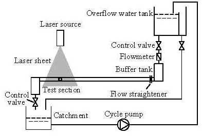
Fig.1 Schematic diagram of experimental setup
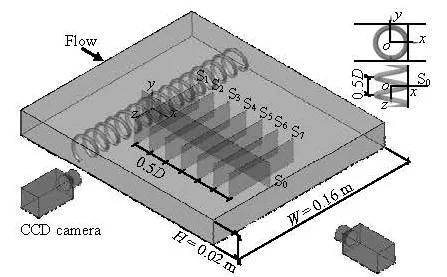
Fig.2 Details of test section
1. Experimental setup
Experiments were performed in a closed-cycle water loop, as shown in Fig.1. The experimental system includes the water circulation system and the PIV measurement system. The water circulation system is comprised of the overflow water tank, the flow meter, the buffer tanks, the flow straightener, the Fig.2 has a narrow rectangular cross section with a width of W=0.16m , a height of H=0.02m and a length of L=1.20m. To achieve a uniform flow, a test section, the catchment tank, the cycle pump and the flow control valves. The test section as shown in flow straightener is installed close to the inlet of the channel. In order to ensure good visual conditions for PIV measurements, the channel is constructed with transparent acrylic sheets of 0.008 m in thickness and the spiral coil is made of transparent acrylic rod of 2.8×10⁻³m in diameter, with an external diameter of D=0.02m and a pith of P=0.01m. In the experiment, the flow is adjusted via the flow control valves to provide a mean velocity range of 0.01 m/s-0.1 m/s, which corresponds to a Reynolds number range of 220-2 250 based on the channel height.
The PIV is a non-intrusive laser optical velocimetry technique for studies of such as flow field measurements and experimental verification of CFD models[12,13]. In this study, the flow measurements were performed using a Dantec Dynamics Digital PIV system. The PIV system mainly includes the laser source, the laser sheet, the CCD digital camera and the synchronizer. A double pulsed Nd: YAG Laser with a wave length of 532 nm and a maximum energy output of 200 mJ per pulse was used to illuminate the measurement planes. Glass beads were used as seeding particles with diameter of about 25 μm and density of 1.05×10³kg/m3. The movement of the seeding particles was recorded using a CCD camera with a resolution of 1 344×1 024 pixels, equipped with a NIKON 60 mm lens. The laser pulses and the camera were triggered with desired sequence and timing by using a high precision synchronizer. The data processing and the evaluation were carried out with the software FlowManager (version 4.71) developed by Dantec Dynamics. In the present investigation, a cross correlation method was used working with two single exposures on a double frame. The size of the interrogation window was 64×64 pixels, with 50%×50% overlap. With the setup of the present measurements, a space resolution of approximately 34 μm/pixel is achieved with a field of view of 0.02 m×0.046 m by masking the area out of the channel. The seeding concentration was adjusted to have 5 to 10 particles in each interrogation window. For each flow condition, the time lag between two images was chosen to reach a mean particle displacement of about 25% of the interrogation area width to meet the requirement of the algorithm. According to studies in literature[14,15], the uncertainty in the velocity field was less than 2% in a two dimensional PIV system, and in the current study it was estimated to be 1.7%.
In the experiment, the spiral coil was placed at a distance of 50D downstream from the test section inlet to ensure a fully developed flow condition. Sincethe practical flow was complicated and three-dimensional, the flow fields of the transverse and longitudinal sections were both measured so as to explore the flow structure caused by the spiral coil in detail. The positions of the laser sheets are shown in Fig.2. The longitudinal measurement plane0S is placed at the middle of two turns of the coil. The transverse measurement planes1S to7S originate from the rear edge of the coil with an equal space of 0.5D. The coordinate system shown in Fig.2 is adopted in the data analysis and the origin is located on the axis of the coil.
2. Results and discussions
2.1 Parameter definitions
The Reynolds number based on the channel height is defined as

where u is the average velocity, ν is the kinematic viscosity and H is the channel height.
The streamwise vorticityxΩ is defined as

whereyu andzu are the velocity components in y and z directions, respectively.
The longitudinal section turbulence intensityxyI is defined as

wherexu' andyu' are the velocity fluctuations in x and y directions, respectively.
2.2 Flow structure in transνerse section
In the present experiments, the transverse section measurements were performed at sections1S to7S along the streamwise direction to investigate the flow characteristics in the channel. To determine the time averaged mean flow structure, 300 instantaneous velocity fields were measured. Due to space limitations, only the flow and vorticity fields at Re=1124 are shown in Fig.3. It can be seen that multi-longitudinal vortices were induced by the spiral coil. The distribution of the velocity vectors and vortices in these sequential transverse sections is well in consistency with the general behavior of the multi-longitudinal vortices, including the generation of the vortices, their gradual deformation and the decrease of their strength as they move downstream. It can be observed from section S1that two counter-rotating vortex pairs (such as1V and2V) are formed behind each turn of the coil. These vortex pairs arrange regularly in accordance with the coil pitches in a symmetrical longitudinal vortex array along the horizontal central line of the transverse section. In the vortex array, any two adjacent vortices rotate in opposite directions to form two different flow patterns in the near wall region, one is the flow towards the wall and the other is the flow away from the wall, causing the fluid downstream of the coil to churn. This churning motion transports fluid from the wall into the free stream and vice versa. In addition, an acceleration can be seen between both adjacent vortices, which indicates that the longitudinal vortices can significantly increase the velocity componentsyu in the wall normal direction. The above flow characteristics caused by the longitudinal vortices can effectively augment the perturbations in the near wall region and promote the mass transfer between the boundary layer and the free stream.
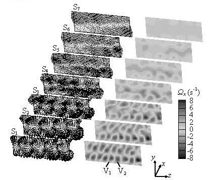
Fig.3 Time averaged flow and vorticity field behind the spiral coil, Re=1124
From the section series of1S to7S it can be seen that as the longitudinal vortices move downstream, the counterclockwise rotating vortices move to the channel walls while the clockwise rotating vortices move to the mid region of the channel with their strength gradually decreasing. However, the effects of the longitudinal vortices on the flow close to the channel walls can still be seen in section S7at x/D=3.5, which further indicates that the longitudinal vortices in the channel can cause continuous disturbance in the boundary layer.

Fig.4 Time averaged flow and vorticity fields at1S and5S
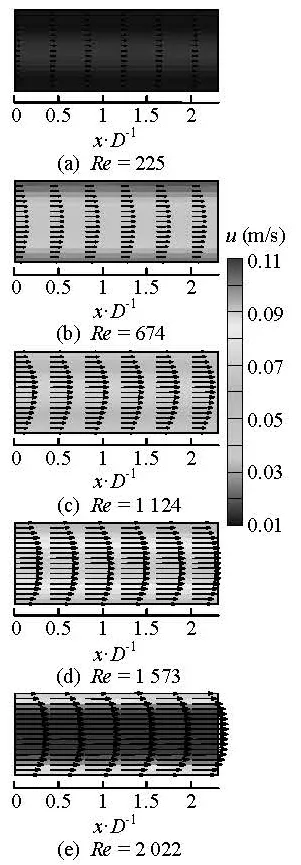
Fig.5 Flow field in the smooth channel
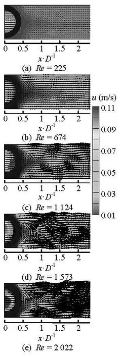
Fig.6 Flow field in the channel with spiral coil insert at0S
Figure 6 shows the instantaneous flow fields in the channel with a spiral coil insert under different Reynolds numbers. It can be seen that the velocity vectors fluctuate along the main stream direction downstream of the spiral coil, corresponding to the spiral motion of the longitudinal vortices in the channel. Influenced by this motion, fluid blocks with relatively high velocity appear in the near wall region, which leads to the increase of the velocity component uyin the wall normal direction and cause remarkable disturbance in the boundary layer. For lower Reynolds numbers, the fluctuations mainly appear in the middle of the channel due to lower vorticity intensity. While for higher Reynolds numbers, the fluctuation extends to the channel walls, because the vortices gradually gain strength and become straighter with the increase of the Reynolds number, which makes the longitudinal vortices more close to the channel walls.
A comparison between Fig.5 and Fig.6 shows that after the insertion of the spiral coil the fluid velocity decreases in the middle of the channel, but increases in the upper and lower regions adjacent to the channel walls. As a result, the fluid velocity in the near wall region is increased, which leads to an obvious reduction of the boundary layer. Besides, over a certain distance downstream of the spiral coil, the velocity profile in the channel is getting even, indicating that the velocity gradient in the channel is reduced due to the disturbance effect of the spiral coil.
In order to see the development of the flow downstream of the spiral coil, Fig.7 shows the profiles of the normalized velocity components ux/u and uy/u at four different positions (x/D=0.8, 1.2, 1.6 and 2.0) along the main stream. In the figure, /xD and /yD represent the dimensionless coordinates in x and y directions, respectively. In each sub-figure, the velocity profiles in the smooth channel without spiral coil insert are presented for comparison. It can be seen that for various inflow conditions in the smooth channel, the ux/u profiles all take a smooth parabolic shape and the uy/u are all close to zero, which indicates a large velocity gradient and a small velocity fluctuation in the channel. However, the velocity profile changes a lot after the insertion of the spiral coil. Influenced by the induced longitudinal vortices downstream of the spiral coil, the ux/u sees two peaks in the upper and lower regions of the channel, at the locations of the longitudinal vortices. As a result, the ux/u profiles take the shape of saddle, rather than the parabolic one in the smooth channel. Because the two peaks are close to the channel walls, the ux/u at y/D=0.45 are all increased to reach or exceed 1, which means that the near wall velocity approaches to the average velocity of the main stream. Compared with the case of the smooth channel, the insertion of the spiral coil leads to an increase of ux/u more than 60% on the wall, from 0.65 to 1.13 at Re=674 and from 0.75 to 1.22 at Re=2022.

Fig.7 Comparison of velocity profiles before and after the insertion of the spiral coil
The effect of an increasing Reynolds number can be seen from the two peaks of the ux/u profiles as shown in Fig.7. For a lower Reynolds number, the two peaks of ux/u assume much higher magnitudes and are much closer to each other. While for a higher Reynolds number, the magnitudes of the two peaks of the ux/u are reduced and they are much closer to the channel walls. This can be due to the increase of the turbulence intensity with the increasing Reynolds number, which minimizes the nonuniformity of the velocity distribution in the channel and leads to the decrease of the magnitudes of ux/u peaks. From the comparison of the velocity profiles at x/D=2.0, it can be seen that the profiles tend to be more flat with the increasing Reynolds numbers, which means that it takes a shorter distance for the velocity to reach a uniform state.
In the smooth channel, the velocity component uy/u in the wall normal direction is almost zero, but after the insertion of the spiral coil theuy/u, affected by the induced longitudinal vortices, sees a positive peak and a negative peak in the channel. The absolute value of uy/u is relatively high at x/D=0.8, 1.2,the places much closer to the spiral coil, and it gradually deceases as the flow evolves downstream. The maximum absolute value of uy/u can reach above 0.3. The increase of uy/u results in an intensification of the transverse mixing action and the mass transfer in the channel.
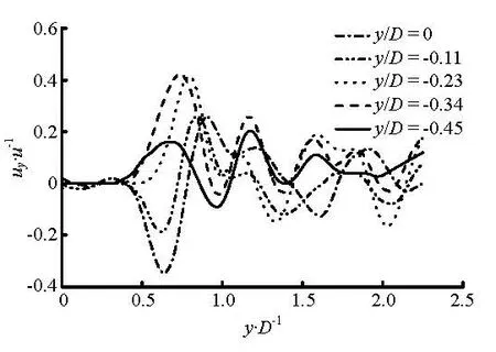
Fig.8 Instantaneous velocity profile of uy/u along the main stream, Re=1124
Figure 8 shows the instantaneous profiles of the velocity component uy/u in the wall normal direction along the main stream direction at Re=1124. Since the flow is approximately symmetrical with respect to the central line of the longitudinal section, only the data of uy/u in the lower half of section S0are presented here. As can be seen from the figure, the velocity profiles begin to fluctuate along the mainstream with a large amplitude from the rear edge of the spiral coil (x/D=0.5) and then decrease gradually in the manner of damped sinusoidal curves. This indicates the velocity fluctuation caused by the spiral motion of the longitudinal vortices along the mainstream. Furthermore, it can be seen that the uy/u profiles fluctuate almost in the same period, and this offers the possibility to deduce the pitch of the spiral motion of the longitudinal vortices in terms of the distance between two adjacent peaks, which accordingly is about 0.3D to 0.4D at Re=1124. A comparison of uy/u at different channel heights shows that the strongest fluctuation of uy/u appears in the region about 0.2D to 0.25D away from the channel walls, corresponding to the location of the induced longitudinal vortices.
Figure 9 shows the velocity profiles of uy/u in the near wall region at y/D=±0.45. As can be seen from the figure, due to the spiral motion of the induced longitudinal vortices, the flow in the near wall region is remarkably disturbed, which leads to a periodic fluctuation of the uy/u profiles. In the region close to the spiral coil, uy/u assumes a relatively large value, and then it decreases as the flow develops downstream. With the increase of the Reynolds number, the vortex intensity is intensified. As a result, the uy/u increases gradually and the persistence distance of the disturbance is increased. The maximum absolute value of uy/u can reach above 0.16 and 0.22 at Re=674 and Re=2022, respectively. The enhancement of the velocity fluctuation close to the wall leads to a significant increase of the turbulence intensity in this area. However, in the smooth channel, the velocity component in the wall normal direction is almost zero. The increase of the velocity component in the wall normal direction is beneficial for the enhancement of the boundary layer disturbance and the mass transfer between the boundary layer and the main stream.
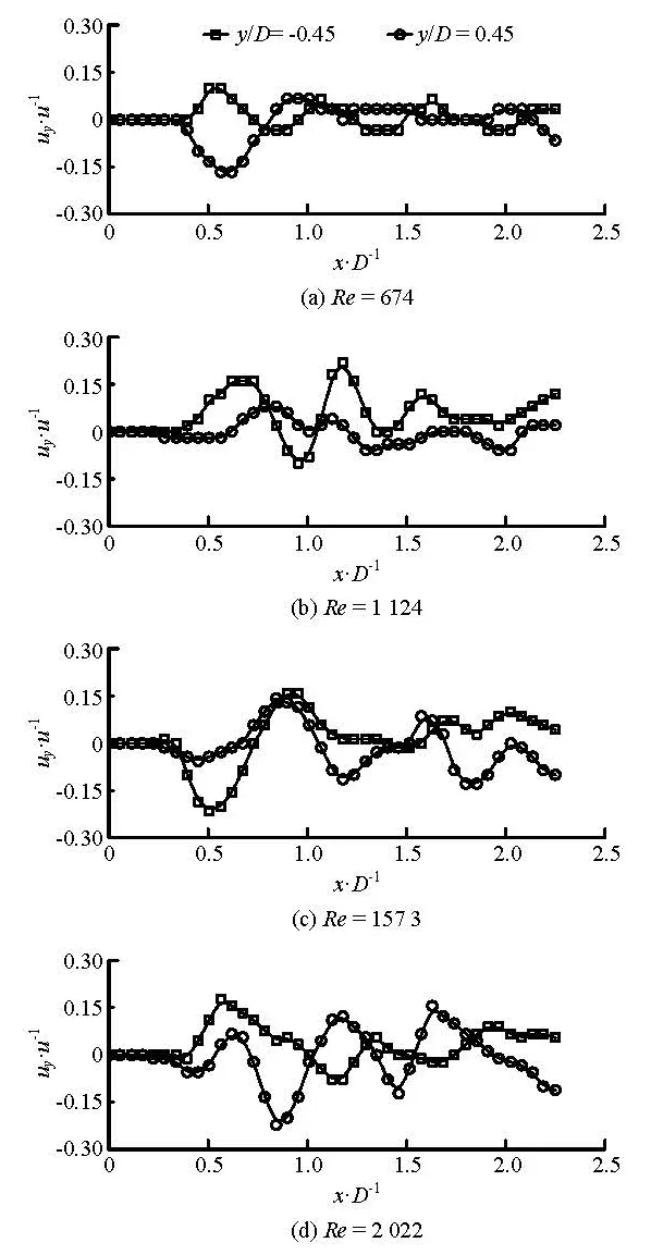
Fig.9 Velocity component uy/u in the near wall region
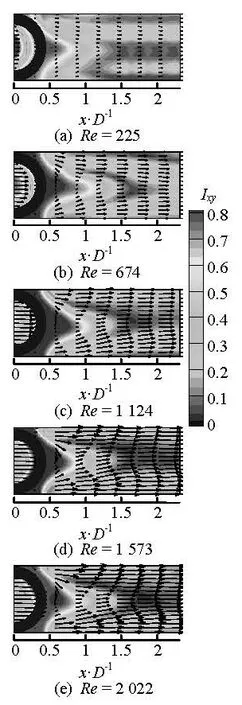
Fig.10 Time averaged flow field and turbulence intensity at S0
The time averaged flow field with the turbulence intensity distribution in section0S is shown in Fig.10. For different Reynolds numbers, the maximum value ofxyI is taken in a triangle region close to the rear edge of the spiral coil. This is because of the guidance of the circular profile of the spiral coil that transports the fluid from the wall into the middle of the channel, which results in relatively high velocity componentsyu in the wall normal direction, which leads to a fierce velocity fluctuation. Besides this triangular area, the relatively highxyI appears in the lower and upper regions of the channel downstream of the spiral coil, at the locations of the longitudinal vortices. At lower Reynolds numbers such as Re=225, strip regions with lower Ixycan be found between the longitudinal vortices and the channel walls, because the strength of the longitudinal vortices is not strong enough to produce effective disturbance on the channel walls. While the Reynolds numbers increase, the longitudinal vortices gain strength and become straighter and closer to the channel walls, which enhances the turbulence intensity on the wall and makes the lowerxyI regions close to the wall disappear. The increase of the turbulence intensity close to the wall means the increase of the velocity fluctuation in this area, which is good for the reduction of the boundary layer.
3. Conclusions
The present study aims to provide some insight into the secondary flows generated by the transversely placed spiral coil in a rectangular channel. Using PIV, the structure of the flow fields in the transverse and longitudinal sections were investigated. The major conclusions are as follows:
(1) In the rectangular channel, multi-longitudinal vortices can be induced downstream of the transversely placed spiral coil insert to form a symmetrical vortex array along the horizontal central line of the transverse section. Any two adjacent vortices are counter-rotating, that makes the flows towards to the wall and away from the wall act reciprocally.
(2) The induced longitudinal vortices increase the fluid velocity in the near wall region and decrease the velocity gradient in the channel, which makes the velocity profile tend to become uniform about 2D downstream of the spiral coil. With the increase of the Reynolds number, the longitudinal vortices become straighter and closer to the channel walls with a growing strength, and consequently increase the turbulence intensity in the near wall region.
(3) The induced longitudinal vortices effectively intensify the continuous disturbance in the boundary layer, enlarge the velocity component in the wall normal direction and promote the mass transfer between the boundary layer and the main stream.
Acknowledgements
This work was supported by the Independent Innovation Foundation of Shandong University (Grant No. 2009TS051), the Graduate Independent Innovation Foundation of Shandong University (Grant No. 31380071613059).
[1] JIANG Bo, TIAN Mao-cheng and LENG Xue-li. Numerical simulation of flow and heat transfer characteristics outside a periodically vibrating tube[J]. Journal of Hydrodynamics, 2008, 20(5): 629-636.
[2] CHEN Y., FIEBIG M. and MITRA N. K. Heat transfer enhancement of finned oval tubes with staggered punched longitudinal vortex generators[J]. International Journal of Heat and Mass Transfer, 2000, 43(3): 417-435.
[3] FERROUILLAT S., TOCHON P. and GARNIER C. et al. Intensification of heat-transfer and mixing in multifunctional heat exchangers by artificially generated streamwise vorticity[J]. Applied Thermal Engineering, 2006, 26(16): 1820-1829.
[4] ALLISON C. B., DALLY B. B. Effect of a delta-winglet vortex pair on the performance of a tube-fin heat exchanger[J]. International Journal of Heat and Mass Transfer, 2007, 50(25-26): 5065-5072.
[5] CHU P., HE Y. L. and LEI Y. G. et al. Three-dimensional numerical study on fin-and-oval-tube heat exchanger with longitudinal vortex generators[J]. Applied Thermal Engineering, 2009, 29(5-6): 859-876.
[6] LEI Y.-G., HE Y.-L. and Tian L.-T. et al. Hydrodynamics and heat transfer characteristics of a novel heat exchanger with delta-winglet vortex generators[J]. Chemical Engineering Science, 2010, 65(5): 1551-1562.
[7] HIRAVENNAVAR S. R., TULAPURKARA E. G. and BISWAS G. A note on the flow and heat transfer enhancement in a channel with built-in winglet pair[J]. International Journal of Heat and Fluid Flow, 2007, 28(2): 299-305.
[8] WU J. M., TAO W. Q. Numerical study on laminar convection heat transfer in a rectangular channel with longitudinal vortex generator. Part A: Verification of field synergy principle[J]. International Journal of Heat and Mass Transfer, 2008, 51(5-6): 1179-1191.
[9] TIAN L.-T., HE Y.-L. and LEI Y.-G. et al. Numerical study of fluid flow and heat transfer in a flat-plate channel with longitudinal vortex generators by applying field synergy principle analysis[J]. International Communications in Heat and Mass Transfer, 2009, 36(2): 111-120.
[10] TANG Yu-feng, TIAN Mao-cheng and ZHANG Guanmin et al. Flow and heat transfer analysis of flat plate channel with spiral coil inserts[J]. Proceedings of the Chinese Society of Electrical Engineering, 2011, 31(2): 55-61(in Chinese).
[11] TANG Yu-feng, TIAN MAO-cheng and ZHANG Guanmin. Experimental investigation of flow and heat transfer in flat plate channel with spiral coil inserts[J]. Journal of Engineering Thermophysics, 2010, 31(11): 1925-1928(in Chinese).
[12] FAN Jing-yu, ZHANG Yan and WANG Dao-zeng. Experimental study on the vortex formation and entrainment characteristics for a round transverse jet in shallow water[J]. Journal of Hydrodynamics, 2009, 21(3): 386-393.
[13] FAN Hui-min, HONG Fang-wen and ZHANG Guoping et al. Applications of CFD technique in the design and flow analysis of implantable axial flow blood pump[J]. Journal of Hydrodynamics, 2010, 22(4): 518-525.
[14] LIU Y. Z., SHI L. L. and YU J. TR-PIV measurement of the wake behind a grooved cylinder at low Reynolds number[J]. Journal of Fluids and Structures, 2010, 27(3): 394-407.
[15] GURLEK C., SAHIN B. Particle image velocimetry studies around a rectangular body close to a plane wall[J]. Flow Measurement and Instrumentation, 2010, 21(3): 322-329.
10.1016/S1001-6058(11)60273-4
* Project supported by the Shangdong Province Key Scientific and Technological Project (Grant No. 2008GG10007009).
Biography: TANG Yu-feng (1982-), Male, Ph. D.
TIAN Mao-cheng,
E-mail: tianmc65@sdu.edu.cn
- 水动力学研究与进展 B辑的其它文章
- MODELING DAM-BREAK FLOOD OVER NATURAL RIVERS USING DISCONTINUOUS GALERKIN METHOD*
- TURBULENCE TRANSPORT OF SURFACTANT SOLUTION FLOW DURING DRAG REDUCTION DEGENERATION*
- NUMERICAL STUDIES ON LOCOMOTION PERFROMANCE OF FISHLIKE TAIL FINS*
- THEORETICAL AND EXPERIMENTAL STUDIES OF THE FLARING GATE PIER ON THE SURFACE SPILLWAY IN A HIGH-ARCH DAM*
- A NEW NUMERICAL WAVE FLUME COMBINING THE 0-1 TYPE BEM AND THE VOF METHOD*
- THREE-DIMENSIONAL NUMERICAL SIMULATION OF WAVE SLAMMING ON AN OPEN STRUCTURE*

