THEORETICAL AND EXPERIMENTAL STUDIES OF THE FLARING GATE PIER ON THE SURFACE SPILLWAY IN A HIGH-ARCH DAM*
LI Nai-wen, LIU Chao
State Key Laboratory of Hydraulics and Mountain River Engineering, Sichuan University, Chengdu 610065, China
College of Hydraulic and Hydroelectric Engineering, Sichuan University, Chengdu 610065, China,
E-mail: gxqlnw@yahoo.com.cn
DENG Jun
State Key Laboratory of Hydraulics and Mountain River Engineering, Sichuan University, Chengdu 610065, China
ZHANG Xiao-zhe
College of Hydraulic and Hydroelectric Engineering, Sichuan University, Chengdu 610065, China
(Received September 24, 2011, Revised June 19, 2012)
The experimental studies of the flaring gate pier applied on the surface spillway in a high-arch dam show that a shock-wave will appear when the pattern of the flow is kept as super-critical. Meanwhile, the water depth at the outlet increases significantly, the flow moves downward in different directions, and the plunging jet is in a narrow and long shape, with a full longitudinal diffusion. In addition, the variation of the flaring gate pier design parameters affects little the discharge capacity of the surface spillway, these parameters including the contraction ratio β, the contraction angle α and the spillway chute angle θ. The pressure on the bottom of the spillway increases along the way and reaches the maximum before the outlet, and then decreases rapidly. Due to the flow impacting, the pressure on both sidewalls increases abruptly at the turning line of the flaring gate pier. To see the characteristics of the flow in the flaring gate pier, a simple calculation method is suggested based on the conversation of energy and mass, and the calculation methods for the jet trajectory and the horizontal length in air are also proposed. The results are found in good agreement with experimental data.
high-arch dam, flood discharge and energy dissipation, flaring gate pier, hydraulic calculation, jet trajectory distance
Introduction
The earlier approach for the flood discharge and the energy dissipation in high-arch dams (200 m or above) is to use free flip buckets with a plunge pool[1]. The plunging jets are used to impact the slab of the plunge pool to generate high hydrodynamic pressures and strong pressure fluctuations, with rapidly varying cycles of loading and unloading of forces acting on each concrete or rock block slabs, with possible damages[2-4]. In order to effectively reduce the hydrodyna-mic pressure on the pool slab, the jets should be spread as much as possible before impacting the slab[5,6]. Motivated by this idea, the surface spillways and the mid-level outlets are adopted for flood discharge in Ertan arch dam (240 m high). This scheme forces the jets from the surface spillways and the midlevel outlets to collide in air and to be broken up, forming spallations or sprays. Since the jets are widely dispersed, the hydrodynamic pressure on the pool slab is largely reduced. However, the collision of jets in air generates a strong spray, which greatly increases the rainfall intensity and the rainfall area and may cause landslides to endanger the dam[7].
Obviously, if the jets from the surface spillways and the mid-level outlets do not collide in air, the excessive spray would be relieved significantly. In a narrow valley, one feasible way is to apply the contracted dissipators on the surface spillways and the midlevel outlets of a high-arch dam, such as flaring gate piers and slit-type buckets[8,9]. By doing this, the longand narrow jets can be obtained and the jet collision in air can be avoided if the jets are directed cross through from each other[10-12].
The hydraulic parameters, such as the depth, the average velocity and the Froude number Fr of the flow, the jet trajectory and the horizontal length in air, are taken as the parameters in the design of the surface spillway when the flaring gate pier is applied. How to calculate these parameters is the key to the applications of the flaring gate pier to the spillway in a higharch dam[13]. In this paper, detailed experimental studies are carried out to address the above issues, and by analyzing the characteristics of the flow in the flaring gate pier channel and the jet movement in air, a simple method of 1-D hydraulic calculation is proposed based on the conversations of energy and mass. Also the jet trajectory and the horizontal length in air are obtained based on the law of free projectile motion.
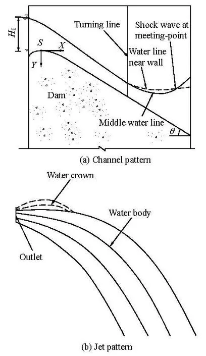
Fig.1 Flow pattern
1. Flow pattern
The flaring gate pier is sited on the tail of the surface spillway in the model. Here, when the pattern of the flow in the surface spillway is kept as super-critical, a shock-wave will appear. Before the junction of the shock-wave, the surface of the flow near the wall is higher than that in the channel center, and the flow at the cross section is in a “U” shape. However, behind the junction, the surface near the wall is lower than that in the center, the “U” shape of the flow turns upside down. The flow is a fully developed 3-D turbulent flow as shown in Fig.1(a).
At the outlet, the flow becomes narrow and high. Although the velocity magnitude of the flow particle changes little, its direction changes greatly. At the outlet, the flow particles move downward in different directions, and the plunging jet is in a narrow and long shape in air, which diffuses fully in the longitudinal direction. As shown in Fig.1(b), the small stream at the upper part of the plunging jet is called the water crown, formed by the shock-wave, and the lower part is the main body of the jet. The water crown falls down on the main flow body due to the gravity and plunges into the pool together.
If the flow Fr is less than 1 at the outlet of the flaring gate pier, the flow will be in a sub-critical regime. At this time, the flow pattern changes from the super-critical flow into sub-critical one in the channel, and the hydraulic jump will occur. The plunging jet is no longer diffusive in the longitudinal direction. A long and narrow jet can not be obtained any more.
So, if we want to get the long and thin jet diffusing fully in the longitudinal direction, we should reasonably adjust the parameters of the flaring gate pier and the total upstream head0H to keep the flow pattern in the spillway and outlet in a super-critical state.
2. Discharge capacity
The necessary assumption of the flaring gate pier applied on the surface spillway is that the discharge capacity of the spillway should not be reduced. As demonstrated in the studies of Li et al.[14], when the flow in the flaring gate pier channel is in a sub-critical state, the discharge capacity of the spillway will be reduced. Therefore, the flow should be kept in the super-critical state throughout during the model test.

The overflow weir of the surface spillway is the WES weir, and the discharge can be calculated by the following formula. where Q is the discharge of the surface spillway, which is measured by a thin triangle weir in the model test, m is the discharge coefficient, B is the width of the surface spillway, g is the gravity acceleration, and0H is the total upstream head of the surface spillway.
From Eq.(1), we have

The value of the discharge coefficient m is thetoken of the discharge capacity of the surface spillway. The design parameters of the flaring gate pier are varied in the test, and the relation curve between m and0H is obtained, as shown in Fig.2.
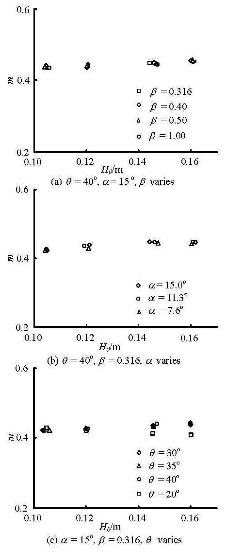
Fig.2 Discharge capacity of the falling spillway
Figure 2 shows that the variations of the design parameters of the flaring gate pier have little effect on the discharge capacity of the surface spillway when the flow is super-critical in the channel, and the design parameters include the contraction ratio β, the contraction angle α and the spillway chute angle θ. We haveβ=b/B, α=arctan[(B-b)/2L]= arctan[(1-β)/2L/B], as illustrated in Fig.5. However, if the flow pattern changes into the sub-critical one, the discharge capacity of the surface spillway would be reduced significantly. In Fig.2(c), the discharge coefficient m is reduced when =θ20o, which is because the channel flow changes from the supercritical flow into a sub-critical one. This result agrees with the studies of Li et al.[14].
3. Flow channel pressure distribution
As shown in Fig.1(a), when the water flows downward, the streamline firstly curls naturally at the crest of the spillway. Then the streamline continues to curl rapidly because of the shock-wave and the narrowing channel. The pressure measured on the surface of the spillway consists of two parts, the hydrostatic pressureHP, and the centrifugal pressureCP caused by the streamline curving.
Then the total pressure can be expressed as

where ρ is the density of the water , h is the water depth, V is the velocity of the flow, and R is the curvature radius of the streamline, which are related to the design parameters of the spillway and the flaring gate pier.
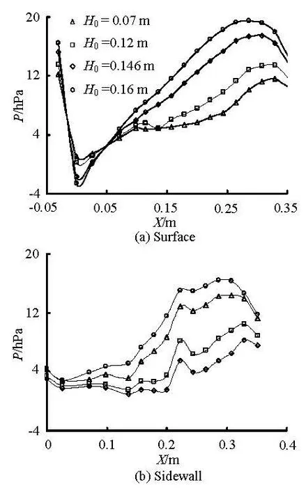
Fig.3 Pressure distribution when β=0.136, α=15o, θ= 30o
At the crest of the spillway, the direction of the centrifugal pressureCP is in the opposite direction of the hydrostatic pressureHP, therefore, the total pressure P is reduced. As shown in Fig.3(a), the minimum value of P is reached at the downstream side of the spillway but near the crest and decreases with the increase of the total water head0H of the weir. P is negative when0H is high but is greater than -30 kPa, which is usually used as an index to be controlled for preventing the cavitation erosion of thespillway.
As the water moves downward, the direction of the streamline curling changes gradually, at last, the direction of the centrifugal pressureCP is the same as that of the hydrostatic pressureHP, so the total pressure P increases, which reaches the maximum near the outlet of the flaring gate pier, and then diminishes quickly when the jet falls down in air.
It can be seen from Fig.3(b) that the pressure distribution on the wall of the flaring gate pier is similar to that on the spillway surface. The difference is that the pressure on the wall has a sudden increase at the turning line of the sidewall, caused by the flow hitting.
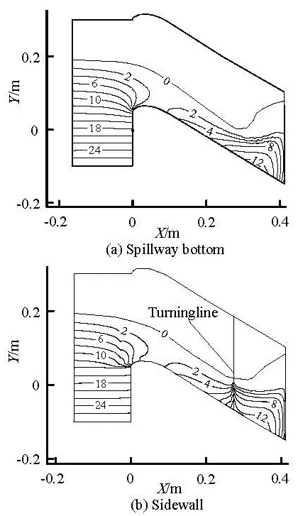
Fig.4 Pressure distribution obtained by the 3-D numerical simulation (hPa)
As shown in Fig.4, the pressure distribution of the spillway with the flaring gate pier obtained by the 3-D numerical simulation agrees in the general trend with the experimental results. Here β=0.136, α= 15o, θ=30oand H0=0.12m.
4. Flow motion analysis and hydraulic calculation
When the flood is discharged through the surface spillway with the flaring gate pier, the flow velocity increases and the depth decreases. In the contracted section of the flaring gate pier, a shock-wave occurs, and the flow is in a complex 3-D motion. The streamline curls rapidly, the depth at the outlet increases significantly, and the flow particles move downward in different directions. The plunging jet will be a narrow and long one, with a full longitudinal diffusion.
According to the law of free projectile trajectory, when a flow particle moves with a certain angle in air, the horizontal length will be the maximum. This angle is defined as the outflow anglemφ of the jet. When the outflow angle of a flow particle is larger thanmφ, the flow particle will soon fall down after moving up to the highest point, then attach to the flow below and plunge into the pool together. Only the flow particles with outflow angle φ less thanmφ are free to fall in air.
The whole process of the flow moving down in the surface spillway can be divided into three steps, i.e., (1) flowing in the surface spillway before the contracted section of the flaring gate pier, (2) flowing in the flaring gate pier, and (3) the jet free falling in air.
The flow pattern in the spillway with the flaring gate pier is very complex as a 3-D flow, and it is difficult to find a simple method for calculating the depth, the velocity and the pressure distribution. To simplify the derivation, the following assumptions are made: (1) the depth and the velocity of the flow section are uniformly distributed, (2) only the hydrostatic pressure is present without consideration of the centrifugal pressure caused by the streamline curving, (3) the head loss coefficient changes evenly along the flow.
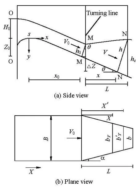
Fig.5 Hydraulic calculation on flaring piers
4.1 Hydraulic calculation in the spillway before the
contracted section of flaring gate pier
As shown in Fig.5, the conservation equations of energy and mass are used between the section O-O and the starting contracted section M-M, to obtain


where0ζ is the head loss coefficient, which is related to the type of weir and the position of the flaring gate pier on the spillway, and ranges from 0.80-0.85[15].
From Eqs.(4) and (5), it follows that

where Q, B,0H,0Z, θ,0ζ are the known variables. Equation (6) is a cubic algebraic equation of h0, which can be solved by the iterative method. So the depth h0of the starting contracted section of flaring gate pier can be obtained.
The head loss coefficient ζ changes evenly along the flow, in the way that ζ=1-s'/s (1-ζ0). Here s' is the distance from the point S to the section calculated in Fig.5(a), s is the distance from the point S to section M-M. So the depth h of different sections can be obtained from Eq.(6).
4.2 Hydraulic calculation in the flaring gate pier
The section N-N is in a trapezoidal shape, as shown in Fig.5. The equations of energy and mass can be written for the part between sections M-M and N-N as

where ξNis the head loss coefficient,is the mean width of section N-N. According to the geometrical relation shown in Fig.5, it follows that,

where
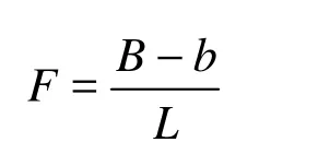
From Fig.5, we have also

Substituting Eqs.(8), (9) and (10) into Eq.(7), we have
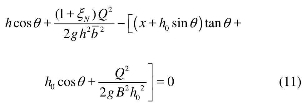
The value of x must satisfy the following inequality

When x takes a certain value, Eq.(11) is an equation of h, which can be solved by the iterative method too.
The water deptheh at the outlet of the flaring gate pier is calculated by the following equation

where hxis the water depth of section N-N when x+hsinθ=L.
The average velocity Veand the Froude number Freat the outlet are determined by the following equations

The head loss coefficient ξNchanges evenly along the flow, in a way that ξN=x/Lξ. On the outlet section, ξ is related to the design parameters of the flaring gate pier, such as the contraction ratio β, the contraction angle α, the relative length of the contraction section /LB and the spillway chute angle θ. According to the dimensional analysis and the multiple linear regression analysis on the experimental data, we have

The linear correlation coefficient is =R 98.072%95%>.
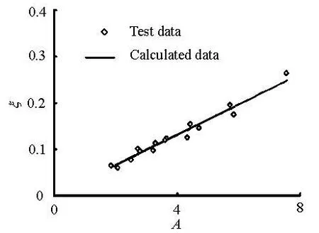
Fig.6 The ξ value of calculations and tests
In Fig.6, A =β-2.578θ1.922(L/B)-1.061. The applicable range of the parameters in Eq.(16) is as follows: 0.3≤β≤0.5, 30o≤θ≤40o, 0.933≤L/B ≤2.562. For parameters with values beyond these ranges, ξ should be determined by the model test.
4.3 Hydraulic calculation of the jet trajectory and
从目前来看,社会最需要的就是应用型人才。可见,培养学生的综合素养和专业技能是至关重要的。而将多媒体应用在大学普通化学教学中,既可以融合学习知识并增强能力,又可以统一信息交流与开发智能,这不仅有助于教师更好地教学,还有助于学生更好地学习,从而满足当今社会对应用型人才的需求。
horizontal length in air
According to the law of free projectile trajectory in air, the formula of calculating the horizontal length travelled by the flow particle can be written as follows:
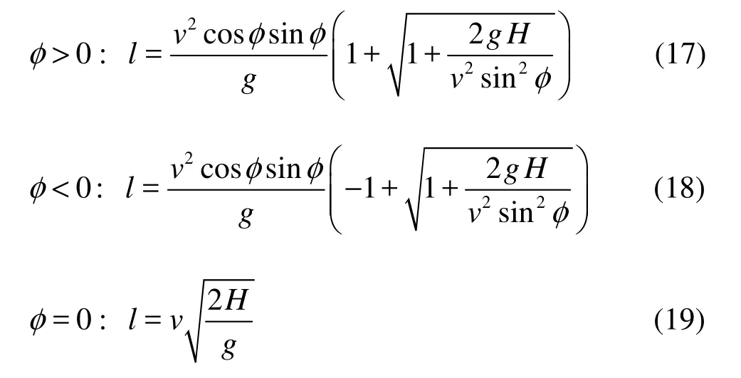
where l is the horizontal length travelled by the flow particle from the outlet to the point of jet plunging in the pool, and H is the vertical distance travelled by the flow particle at outlet to the plunge pool. For the horizontal length of the jet outer fringe, we have H=he+Z and l=l1, and for the jet inner fringe, H=Z and l=l2. Z is the vertical distance between the outlet and the pool, v is the initial velocity of the flow particle, and φ is the angle of the initial velocity vector.
It can be seen from Eqs.(17)-(19) that once the values of φ, v andeh are given, the jet trajectory and the horizontal length in air can be calculated accurately. So the key of the problem is how to calculate the outflow angle φ, the initial velocity v and the water deptheh at the outlet of the spillway with the flaring gate pier.
Influenced by the shock-wave, a water crown occurs at the top of the plunging jet, as shown in Fig.4(b). As the water crown is only a minor fraction of the whole jet to be, which is negligible, only the outflow angle of the main jet is discussed in this paper.
Two important outflow angles are selected and discussed in the paper: the jet outer fringe outflow anglewφ and the jet inner outflow anglenφ.

Then the first derivative is taken for Eq.(20), yielding

Making x=L-hsinθ, the angle φwis expressed as

So the key is to calculate d/dhx.
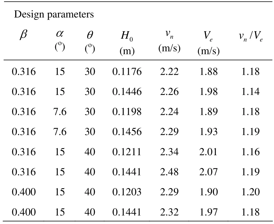
Table 1 The values ofnv andeV of the jet
With the first derivative for Eq.(11), it follows that
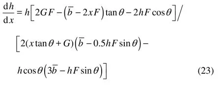
We have

Let x=L-hsinθ, the value of φwcan be obtained through Eqs.(23), (21) and (22).
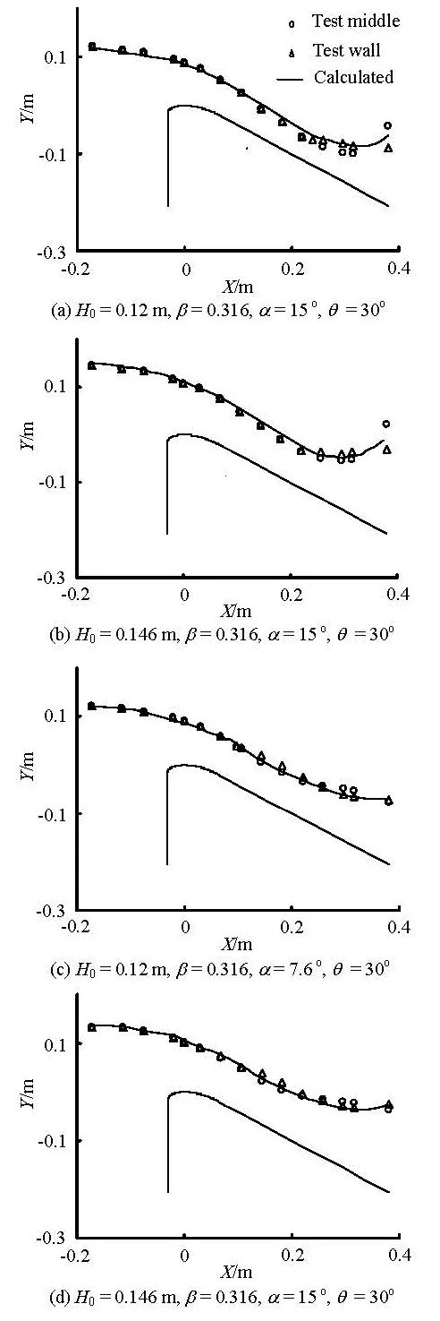
Fig.7 Water curve of spillway with flaring gate pier
When the spillway discharges flood, the jet is bounded by the bottom of the spillway. Therefore, the jet inner outflow anglenφ and the spillway chute angle θ are basically identical, which is slightly influenced by other parameters such as the total head of the spillway0H, the contraction ratio β, and the contraction angle α. So, we have According to the law of free projectile trajectory, we have


Taking the derivative of Eq.(25) with respect to φ and let d/d=0lφ, the outflow angle φ of the jet with the maximum horizontal jet distance can be obtained as

In calculating the maximum horizontal jet distance, the largest amongwφ andmφ will be taken as φ.
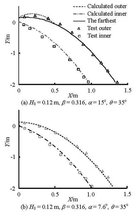
Fig.8 Jet trajectory in air
According to the studies of Li et al.[14], when the flaring gate pier is applied to the surface spillway, the magnitude of the velocity at the jet outer fringe sees little difference with the average velocity on the flowsection, but its direction changes greatly. So the average velocity on the outlet section can be used for the velocity at the jet outer fringe in the computation, that is vw=Ve.
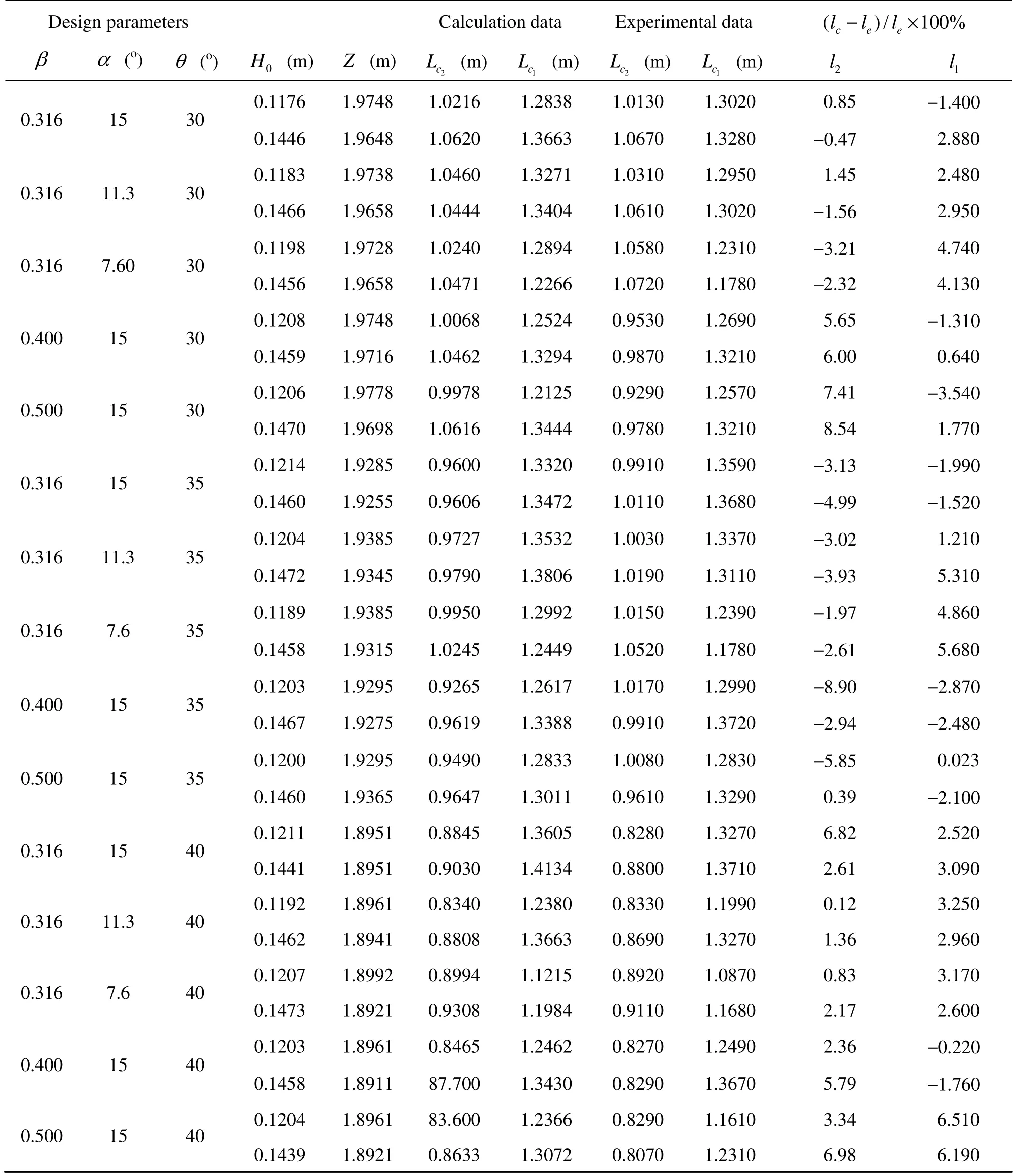
Table 2 The horizontal length of jet from spillway with flaring gate pier
However, the velocity at the jet inner fringenv on the outlet section is actually larger thaneV. Therefore the horizontal length of the jet inner fringe will be markedly less than the experimental data ifeV is used fornv. As shown in Ref.[14], the maximum velocity on the outlet section is larger than the average value on the section by 16%. In this paper, the 3-D numerical simulation is used to calculate thenv of the plunging jet from the flaring gate pier on the spillway. The data of the 3-D numerical simulation and thetest are listed in Table 1.
The data in Table 1 shows that the ratio ofnv andeV is between 1.14 and 1.20, which is in good agreement with that in Ref.[14]. Taking the average value of the ratio vn/Veto calculate vn, that is, vn=1.18Ve.
5. The results and comparisons
For various values of the total head of the spillway0H and the design parameters of the flaring gate pier (,,βαθ), the water surface curves for the spillway are calculated, as shown in Fig.7, and the calculated jet trajectories in air are illustrated in Fig.8. The calculated horizontal length of the jet outer fringe l1and the jet inner fringe l2are listed in Table 2, which are compared with the experimental data.
Figures 7, 8 and Table 2 demonstrate that in general the calculated results are in good agreement with the experimental data with errors mostly less than 5%. Only in some parts, the errors exceed 5% but are less than 10%. This shows that the hydraulic method for the flaring gate pier on the spillway proposed in this paper is feasible and can produce reliable results, which can be used as a design tool for the flaring gate pier applied to the surface spillway in a higharch dam.
6. Conclusions
This paper carries out both the theoretical analysis and the experiments to study the flow pattern, the discharge capacity, the pressure distribution in the channel and the hydraulic calculation for the flaring gate pier applied on the surface spillway in a higharch dam. The conclusions are as follows:
(1) When the flow is in a super-critical regime in the surface spillway, a shock-wave will occur. The streamline curls rapidly, and the water depth at the outlet increases significantly. Then the flow particles move downward in different directions. Thus the plunging jet will be a narrow and long one, with a full longitudinal diffusion.
(2) When the flow in the spillway is super-critical, the design parameters of the flaring gate pier have little effect on the discharge capacity.
(3) The total pressure increases along the spillway, reaches the maximum near the outlet of the flaring gate pier, and then diminishes quickly. The pressure on the wall has a sudden increase at the turn line, due to the flow hitting.
(4) The method of the hydraulic calculation for the flaring gate pier flow is developed based on the conversation of energy and mass, and the calculated results are in good agreement with experimental data.
(5) Based on the law of free projectile trajectory, the hydraulic equation for the jet trajectory and the jet outer or inner fringe horizontal length of the flaring gate pier is derived. The calculated data are very close to the experimental data.
[1] XU Wei-lin, LIAO Hua-sheng and YANG Yong-quan et al. Turbulent flow and energy dissipation in plunge pool of high arch dam[J]. Journal of Hydraulic Research, 2002, 40(4): 471-476.
[2] LIU Pei-qing, LI Fu-tian. Model discussion of pressure fluctuations propagation within lining slab joints in stilling basins[J]. Journal of Hydraulic Engineering, ASCE, 2007, 133(6): 618-624.
[3] SUN Jia-wen, SUN Zhao-chen and LIANG Shu-xiu et al. Spectral analysis of random wave uplift force on a horizontal deck[J]. Journal of Hydrodynamics, 2011, 23(1): 81-88.
[4] MANSO P. A., BOLLAERT E. F. R. and SCHLEISS A. J. Influence of plunge pool geometry on high-velocity jet impact pressures and pressure propagation inside fissured rock media[J]. Journal of Hydraulic Engineering, ASCE, 2009, 135(10): 783-792.
[5] MANSO P. A., BOLLAERT E. F. R. and SCHLEISS A. J. Impact pressures of turbulent high-velocity jets plunging in pools with flat bottom[J]. Experiments in Fluids, 2007, 42(1): 49-60.
[6] MELO J. F., PINHEIRO A. N. Effect of jet aeration on hydrodynamic forces on plunge pool floors[J]. Canadian Journal of Civil Engineering, 2008, 35(5): 521-530.
[7] SU Wei. The Initial run evaluation of surface spillways and middle level outlets in ertan arch dam[J]. The Design of Hydropower, 2001, 17(3): 18-19(in Chinese).
[8] YIN Jin-bu, LIANG Zong-xiang and GONG Hong-lin. Experimental study on flow characteristics of 3D hydraulic jump of flaring gate piers[J]. Journal of Hydraulic Engineering, 2010, 41(11): 1333-1338(in Chinese).
[9] LIU Lu, ZHANG Jian-min and YU Fei et al. Experimental study of hydraulic characters of the flaring gate pier and stilling basin united energy dissipator with high water head and large discharge[J]. Journal of Hydroelectric Engineering, 2012, 31(2): 49-55(in Chinese).
[10] LIU Pei-qing, XU Wei-lin. Study on non-impact energy dissipation of ski-drop flow in plunge pool of high arch dam[J]. Journal of Hydraulic Engineering, 2010, 41(7): 841-848(in Chinese).
[11] DENG Jun, XU Wei-lin and ZhANG Jian-ming et al. A new type of plunge pool-multi-horizontal submerged jets[J]. Science in China Series E: Technological Sciences, 2009, 39(1): 29-38.
[12] JIAO Ai-ping, SUN Wu-ji and ZHOU Chen-chao et al. Study of impinging pressure caused by multi-layer jets downstream of high arch dam[J]. Journal of Hydroelectric Engineering, 2012, 31(1): 114-117(in Chinese).
[13] LI Nai-wen, XU Wei-lin and Zhang Fa-xing et al. Study on numerical simulation of 3D flow formed by flaring gate piers on surface spillways in high arch dams[J]. Journal of Sichuan University (Engineering Science Edition), 2008, 40(2): 19-25(in Chinese).
[14] LI Fu-tian, LIU Pei-qing and XU Wei-lin et al. Experimental study on plunging nappe from surface spillways with flaring gate piers in high arch dams[J]. Water Resources and Hydropower Engineering, 2003, 34(9): 23-25(in Chinese).
[15] MO Zhen-yu, WU Chao and LU Hong et al. Relation ship of location of flaring gate piers, Froude number at section of starting flare andv weir head[J]. Journal of Sichuan University (Engineering Science Edition), 2007, 39(9): 26-30(in Chinese).
* Project supported by the National Natural Science Foundation of China (Grant Nos. 50909067, 51009102), the Program for New Century Excellent Talents in University (Grant No. 2011SCU-NCET-10-0589).
Biography: LI Nai-wen (1975- ), Male, Ph. D., Lecturer
LIU Chao,
E-mail: liuchao@scu.edu.cn
- 水动力学研究与进展 B辑的其它文章
- MODELING DAM-BREAK FLOOD OVER NATURAL RIVERS USING DISCONTINUOUS GALERKIN METHOD*
- TURBULENCE TRANSPORT OF SURFACTANT SOLUTION FLOW DURING DRAG REDUCTION DEGENERATION*
- NUMERICAL STUDIES ON LOCOMOTION PERFROMANCE OF FISHLIKE TAIL FINS*
- A NEW NUMERICAL WAVE FLUME COMBINING THE 0-1 TYPE BEM AND THE VOF METHOD*
- PIV EXPERIMENTAL RESEARCH OF FLOW STRUCTURE IN RECTANGULAR CHANNEL WITH TRANSVERSELY PLACED SPIRAL COIL INSERT*
- THREE-DIMENSIONAL NUMERICAL SIMULATION OF WAVE SLAMMING ON AN OPEN STRUCTURE*

