NUMERICAL STUDIES ON LOCOMOTION PERFROMANCE OF FISHLIKE TAIL FINS*
LI Gao-jin
Department of Modern Mechanics, University of Science and Technology of China, Hefei 230026, China, E-mail: lgjsz@mail.ustc.edu.cn
ZHU Luodin
Department of Mathematical Sciences, Indiana University-Purdue University Indianapolis, Indianapolis, IN 46202, USA
LU Xi-yun
Department of Modern Mechanics, University of Science and Technology of China, Hefei 230026, China
(Received January 15, 2012, Revised March 25, 2012)
Flapping plates of typical fishlike tail shapes are simulated to investigate their locomotion performance using the multi-block Lattice Boltzmann Method (LBM) and Immersed Boundary (IB) method. Numerical results show that fishlike forked configurations have better locomotion performance compared with unforked plates. Based on our results, the caudal fin in carangiform mode has greater thrust, and the lunate tail fin in thunniform mode has higher efficiency. These findings are qualitatively consistent with biological observations of fish swimming. Analysis of wake topology shows that the wake of the forked plate consists of a chain of alternating reverse horseshoe-like vortical structures. These structures induce a backward jet and generate a positive thrust. Moreover, this backward jet has a more favorable direction compared with that behind an unforked plate.
carangiform and thunniform modes, forked-tail fin, three-dimensional (3-D) flapping plate, multi-block Lattice Boltzmann Method (LBM), Immersed Boundary (IB) method
Introduction
Fish usually propel themselves by means of a transverse wave that moves backwards along the body from the head to the tail. For carangiform and thunniform modes, the amplitude of the wave becomes significant only in the posterior part of the fish because the remainder of the body is relatively rigid. Hence the thrust generation is confined almost exclusively to the caudal fin, which can be considered to “flap” in an almost undisturbed free stream. This flapping model was studied extensively to help understand the optimal propulsive performance of fish swimming. Review ofsuch investigations can be found in Refs.[1,2].
Many studies assumed that the Aspect Ratio (AR) of the foil was large and therefore restricted their attention to two-dimensional (2-D) problems. Previous work[3]found that the governing non-dimensional parameter for thrust production and wake pattern can be written as the combination of the flapping frequency f and the peak-to-peak amplitudepA, i.e., the Strouhal number St=fAp/U∞, where U∞is the free stream velocity. Thrust increases monotonically with St, while the efficiency reaches its maximum in an intermediate range of St. Under the condition of efficient propulsion, the flapping 2-D foil generates two vortices per cycle and results in the formation of a reverse Kármán vortex street.
Different from the 2-D case, behind a foil of finite aspect ratio in three-dimensional (3-D), the vortex lines shed from the central part of the foil must bend downstream, and then turn inwards and finally close up when they reach the vorticity of opposite sign shedby the foil half period earlier. So the 3-D topology of the wake consists of a series of vortex rings. This type of ring-like vortical structures behind a flapping foil of finite span has been confirmed. Von Ellenrieder et al.[4]visualized the wake of a pitching and heaving wing of AR=3 at Re=164 and observed that in the range of 0.2<St<0.4, the wake consisted of two merged closed vortex loops shed in each half-cycle, forming a zigzag chain, sometimes with additional appendages. Another series of experiments[5,6]also observed the ring-like structures in the wake of a pitching panel of AR=0.54 at relatively high Strouhal numbers. They found that the vortices shed from the three free edges of the panel form a “horseshoe vortex”, and this vortical structure is important for the formation of the vortex ring. Simulations on this model also reveal the existence of vortex rings in the wake; details of the generation and evolution of these vortical structures were discussed[7-9].
Previous studies on this model mainly concerned the effects of the kinematical parameters, such as the pitching/heaving amplitude, frequency and the phase difference between the pitching and heaving motions. The shapes of the flapping fins were usually simplified as rectangular plates or ellipsoidal foils, which in general can be collectively named as the “unforked foil”. However, caudal fin morphology shows a considerable diversity of the fin in the fish world. The“forked tail fins” are among the most common forms. Studies on the phylogeny of ray-finned fishes revealed the evolution tendency from the primitive heterocercal configuration to the homocercal forked-tail configuration, which suggests the probable advantages of the forked tail configurations compared with the unforked tails[10].
Some studies were carried out to deal with the fish locomotion. Borazjani and Sotiropoulos[11,12]investigated the carangiform swimming to analyze the effects of St and Re on the swimming performance and the vortical structures in the wake. Based on the PIV data, Wang et al.[13]proposed a model of zigzag chain of merging vortex rings behind a flapping foil with carp caudal planform. However, the details of the wake and the effect of the caudal fin were relatively less discussed. To the best of our knowledge, there exist no studies to deal with the effect of the forked configuration on locomotion performance. The full picture of the vortical structures behind the fish tail fins has not yet been drawn.
In the present study, the propulsion performance and the wake structure of an unforked plate and two forked plates undergoing a pitching and heaving motion are simulated with the 3-D multi-block Lattice Boltzmann Method (LBM) and Immersed-Boundary (IB) method. Our attention is mainly focused on the advantages of the forked tails and the relevant vortical structures.
The remainder of the paper is organized as follows. In the next section, the physical models, numerical method, and validation of the code are described. Detailed results are discussed in Section 2 and concluding remarks are made in Section 3.
1. Problem statement and numerical method
1.1 Problem statement
In this study, we simulate the plates with flapping motion in an incompressible viscous flow with constant velocity U∞. The incompressible Navier-Stokes equations are used and given as

The flapping motion is described by a combination of heaving and pitching motions. The heaving motion is in the vertical direction (y) and the pitching motion is around the leading edge of plate,

The governing non-dimensional parameters include the normalized heaving amplitudeyA, the pitching amplitude0θ, the Reynolds number =Re U∞c/v , and the Strouhal number St=2Ayf/U∞, where c is the chord length. It is clear that there exists a very high dimensional parameter space of this problem. However, the laboratory measurements of the fish locomotion[14,15]found that under the optimal thrust production, the ratio of the heave amplitude over the chord length is of the order of 1, the pitching amplitude is between 20oto 30oand the Strouhal number is in the range of 0.250.4St<<. Motivated by these data and to limit the scope of this study, we choose the parameters as follows: Ay=0.5, θ0=30o, Re=500, and St=0.2, 0.3, 0.4, 0.6 and 0.8. Similar values were adopted in a number of past studies[3,7-9].
Here, the thrust coefficient is defined as

whereTF is the thrust force on the flapping plate, and A is the area of plate. Then the propulsive efficiency is calculated by

where L and M represent the lift force and moment, respectively, and overbar means the time-averaged quantities.
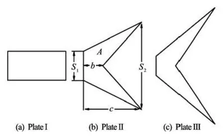
Fig.1 Sketch of the rectangular plate and two fishlike forked plates
We mainly study two shapes of the caudal fins which are the typical configurations in carangiform mode and thunniform mode. Rigid plates are simulated and this assumption is reasonable because the fish caudal fin is relatively stiff in these two modes. As is shown in Fig.1, a rectangular plate I of AR=0.5 is also simulated for comparison. Plate II presents the configuration in the carangiform mode and Plate III shows a typical shape of the lunate tail, which is the common form of thunniform swimmers, such as tuna, mackerel, sailfish, swordfish and sharks. To reduce the variables in the problem, the areas of the two forked plates are set to be the same as the area of Plate I. The specific parameters of the forked tail shapes are obtained via simplification of the data from the observation of fish swimming:1=0.5S,2=1.5S, =b 0.333 and S1=0.167, S2=2 and b=0.333, respectively. The AR for forked tail fin is defined as

Here, AR=4.5 and 8 for Plates II and III, respectively.
1.2 Numerical method and validation
The LBM provides an alternative approach for solving the incompressible viscous flows. Based on mesoscopic kinetic models, the algorithms of the LBM avoid solving the Poisson equation and are simpler compared with the conventional numerical schemes. In our simulation, a multi-block LBM technique[3]is employed to solve the problem. The IB method[16,17], which treats the solid boundary by adding a boundary force to the momentum equations, has been widely applied for problems involving moving bodies. The IB-LBM have been successfully applied for simulations of flapping foils[18]. The hybrid IB-LBM method is briefly described as follows.
The discrete Lattice Boltzmann Equation (LBE) under a single-relaxation-time approximation with body force is written as

where τ is the relaxation time, Δt the time increment, fi(x,t) the distribution function for particles with velocity eiat position x and time t and Gi(x,t) is the external forcing term in the LBE. The D3Q19 model is used, and the equilibrium distribution functionis defined as

whereiω is the weighting factor,sc is the sound speed, and ρ and u are respectively the fluid density and velocity, which can be obtained by the distribution function and the body force g

The forcing termiG in the LBE can be expressed as

The IB approach gives the body force g by distributing the surface forcebg on the Lagrangian grid of the solid bodybx to the Eulerian grid x in the flow field

Here we use the discrete Dirac delta function ()rδ introduced by Peskin[16]

where Δx is the lattice space.bg can be constructed by the feedback law[17,18]

ufis the velocity of the fluid at the Lagrangian grid on boundary surface, which can be interpolated from the Eulerian grid in the flow field using the discrete Dirac delta function ()rδ.bu is the prescribed velocity of the moving boundary of the plate. α and β are the feedback forcing coefficients and are usually set as large negative constants[17,18]. Their specific values are restricted by the time step used in the computation. Simulation results are insensitive to α and β when they are large enough. After the convergence validation of the calculations, we use =2α-× 104and β=-1×10³in the present work as was employed in the previous studies with the same IB method[17,18].
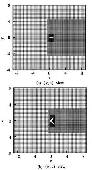
Fig.2 Grid employed in current simulations
Our simulations are performed in a rectangular box of size [-9,9]×[-8,8]×[-8,8] in the streamwise (x), vertical (y) and spanwise (z) directions. The resolution of the corresponding Cartesian grid is 300× 320×320. The multi-block division of the grid is shown in Fig.2. The resolution of the background grid is Δx=c/20, it is doubled in the wake area. The resolution is also doubled in all the region covering the plate motion, with the finest lattice spacing being Δx=c/80. The time step in the simulation is Δt/ T=3200, where T is the flapping cycle. The boundary condition is set to be a uniform flow on all of the boundaries except the outlet boundary where a convective boundary condition (∂u/∂t+U∞∂u/∂x =0) is specified.

Fig.3 Comparison of time history of force coefficients
To validate the code, some typical cases are tested in 2-D including flow around a stationary cylinder and around an oscillating cylinder as well as in 3-D including flow around a stationary sphere, around stationary flat plate wings, and around flapping foils. All the simulations have good agreements with the existing results in literature. Here we only address the comparisons between our 3-D simulation of the flow around the flapping foils and the results of Dong et al.[8]. Figure 3 gives the comparisons of the time history ofTC andLC for three foils of different finite aspect ratios at Re=200 and St=0.6 in one flapping cycle. Figure 4 shows the 3-D vortical structu-res and the spanwise vorticity on the spanwise symmetrical plane for the foil of AR=1.27 at the midphase of the heaving motion. It is seen that the wake topology and the vorticity distribution in our simulation also agree well with the pervious results (see Fig.12 in the paper of Dong et al.[8]).

Fig.4 Wake topology for flapping foil at Re=200 and St=0.6
2. Results and discussion
We investigate the locomotion performance of the two forked plates and the unforked plate using parameters in the optimal parameter range for fish swimming. Connections between our simulation results and the biological observations of fish swimming are analyzed. In Section 2.1, the thrust and the propulsion efficiency are discussed. In Section 2.2, we focus on the wake topology of the forked plates and its difference from that behind the unforked plate.
2.1 Hydrodynamic forces
Figure 5(a) shows the variation of the mean thrust coefficient versus the Strouhal number for the three plates. It is seen that the Strouhal number is the most important parameter for the thrust. The thrust on the forked plates is slightly larger than the one on the unforked plate.
Comparison between the two forked plates shows that Plate II has a lager thrust than Plate III. For example, at =0.4St, the mean thrust is about 0.41 on Plate II and 0.36 on Plate III. For the forked plates, the thrust on the plate of small aspect ratio (AR=4.5) is larger than on the plate of large aspect ratio (AR=8). This result is different from that given in the previous work on the flapping plate with ellipsoidal or rectangular sectional planes[8,9]. Moreover, the present results are qualitatively consistent with the observations of fish swimming, fish with the caudal tails in the shape of Plate II, such as carp, trout and pike, usually have large thrust to gain rapid acceleration and fast swim.

Fig.5 Locomotion performances for three plates
At relatively low Reynolds number (Re=500), the flapping plate has to overcome large shear drag to gain a positive thrust. The Strouhal numbers with the optimal efficiency are around 0.6, which is greater than the St range widely adopted by aquatic animals[15], the magnitude of the peak efficiency is around 0.2. These results agree well with previous studies[8,9]in the similar Re range. Moreover, it is reasonable to speculate that at high Reynolds number Re, the forked tail fins, especially the lunate tail fin, may have a remarkable advantage for higher efficiency.
The variation of the efficiency with St is given in Fig.5(b). The efficiencies reaches the maximum at intermediate values of St. Both forked plates have slightly higher efficiency than the unforked plate and the Plate III is the most efficient one. This finding also agrees with the observation that the thunniform mode, which usually accompanies the lunar tail, is the most efficient locomotion mode adopted in the aquatic environment.
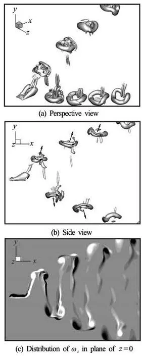
Fig.6 Vortical structures for plate I at t/T=0.5
2.2 Vortical structures
As a typical case, we examine the vortical structures at St=0.6, where the propulsion efficiencies lie in the maximum region. Figures 6(a) and 6(b) show the perspective and side views of the wake behind the Plate I at the phase t/T=0.5. Vortical structures are depicted by the Q criterion

where Ω and S denote the rotation and strain tensors, respectively, andis the Euclidean matrix norm. Here we use the isosurface of =2Q to exhibit the vortical structures. Figure 6(c) shows the spanwise vorticityzω contours from -6 to 6 on the spanwise symmetrical plane. The same value of Q and the same range ofzω are applied for Plates II and III.
For the rectangular plate, it is seen from Fig.6(b) that the wake is mainly composed of two sets of oblique vortex ring structures with the vortex directions and the induced jets indicated by arrows. These jets have a large inclination angle with respect to the streamwise direction, and only a small part of the impulse generated by each vortex ring is utilized for propulsion. Moreover, there is an additional spanwise vortical tube in each vortex ring structure, which is consistent with the similar structure reported by von Ellenrieder et al.[6]
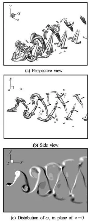
Fig.7 Vortical structures for the Plate II at t/T=0.5
Figures 7(a)-7(c) show the wake topology of the Plate II. It is seen that both the spanwise vorticity distribution and the 3-D wake topology have obvious differences from those in Fig.6. For the forked plate, the wake is composed of a chain of alternating pairs of vortical tubes. In each pair, two vortical tubes connect with each other on the upstream side and extend towards the adjacent pair on the other side to form a horseshoe-like structure. Two legs of the horseshoe are generated from the two tips of the forked plate, these horseshoe-like structures have different orientations from the wake of a pitching rectangular panel of low aspect ratio[5,6], and are called the “reversal horseshoe vortex” for distinction. There are also some other small-scale structures in the wake. With the structures being convected downstream, the small-scale structures and the head part of the horseshoe vortex become weaker and eventually disappear, leaving two separatetubes in the wake. Compared with the vortex rings, each pair of tubes induces a jet which is more inclined to the x-direction and these vortical structures are considered to be more efficient for fish locomotion.
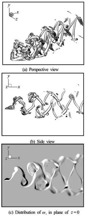
Fig.8 Vortical structures for the Plate III at t/T=0.5
As is shown in Figs.8(a)-8(c), the wake of the Plate III is still mainly composed of pairs of vortical tubes, the distance between two tubes in a pair is larger because of the larger AR and more small-scale vortical structures in the wake. This type of wake behind the flapping fish-like plate can be observed in all the thrust-generating cases. Furthermore, the simulations of Borazjani et al.[11,12]on the carangiform locomotion at Re=4000 and St=0.7 also showed that the double-row pattern is no longer made up of two rows of simple vortex loops but consists of complex and highly 3-D coherent structures connected together through complex columnar structures. The vortical structures in their simulations also showed the formation of the “reversal horseshoe vortex”, especially before they merge together with the adjacent structures. Thus we may draw the conclusion that near the optimal propulsion performance, a chain of alternating reversal horseshoe vortices is the main feature of the wake topology of the forked tail fins.
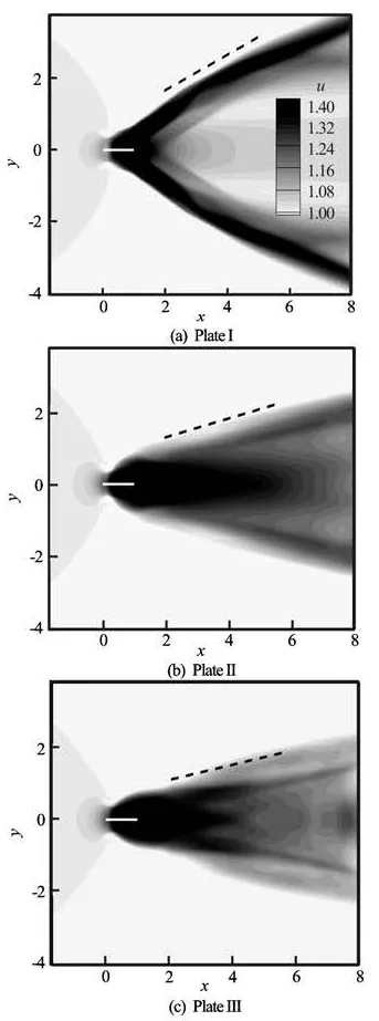
Fig.9 Comparison of the time-averaged jet in the wake
Figures 9(a)-9(c) show the mean streamwise velocity distribution in the spanwise symmetrical plane to compare the time-averaged jets for the three plates. It is seen that behind the unforked plate, the jet bifurcates into two branches corresponding to the two sets of vortex rings in the wake. Each branch of the jets has a relatively larger inclination angle with respect to the streamwise direction, which is about 28oin this case. Moreover, the jet behind the fishlike forked plate is concentrated within a relatively smaller expansion angle and has a more favorable direction. For the forked Plates II and III, the angles are 13oand 11o, respectively.
3. Conclusions
The hydrodynamics and the wake topology of the forked plates undergoing pitching and heaving motion have been studied. The three-dimensional Navier-Stokes equations are solved using the multi-block IBLBM. Based on our computational results, we have gained some physical insight into the propulsion performance of the fishlike tail fins.
The propulsion performances of two typical shapes of the caudal fins are compared with the rectangular plate. Our analysis shows that both the mean thrust and the propulsion efficiency can be increased by the forked configuration, although these advantages are not very noticeable at low Reynolds numbers. Specifically, the configuration in the carangiform mode provides a larger thrust, especially at large Strouhal numbers; the lunate tail in the thunniform mode is more favorable for high efficiency.
The wake topology of the forked plates is different from that of the unforked plate. Instead of two sets of oblique vortex rings behind the rectangular plate, a chain of alternating reverse horseshoe vortices constitutes the main part of the wake. These pairs of vortical tubes induce a more favorable jet for propulsion, which can explain the advantages of the forked tail fins.
Our simulation results of the two fishlike forked plates are in qualitative agreements with the biological observations of fish swimming. It is reasonable to expect that the shape of the forked plate may have an important effect on the locomotion performance. Our results also show that the wake topology of the fishlike foil is obviously different from the extensively studied wake of the unforked foil, indicating that more reliable biological factors should be considered to better understand biological locomotion.
[1] TRIANTAFYLLOU M. S., TECHET A. H. and HOVER F. S. Review of experimental work in biomimetic foils[J]. IEEE Journal of Oceanic Engineering, 2004, 29(3): 585-594.
[2] MITTAL R. Computational modeling in biohydrodynamics: Trends, challenges, and recent advances[J]. IEEE Journal of Oceanic Engineering, 2004, 29(3): 595-604.
[3] ZHANG J., LIU N. S. and LU X. Y. Locomotion of a passively flapping flat plate[J]. Journal of Fluid Mechanics, 2010, 659: 43-68.
[4] Von ELLENRIEDER K. D., PARKER K. and SORIA J. Flow structures behind a heaving and pitching finitespan wing[J]. Journal of Fluid Mechanics, 2003, 490: 129-138.
[5] BUCHHOLZ J. H. J., SMITS A. J. On the evolution of the wake structure produced by a low-aspect-ratio pitching panel[J]. Journal of Fluid Mechanics, 2003, 546: 433-443.
[6] BUCHHOLZ J. H. J., SMITS A. J. The wake structure and thrust performance of a rigid low-aspect-ratio pitching panel[J]. Journal of Fluid Mechanics, 2008, 603: 331-365.
[7] BLONDEAUX P., FORNARELLI F. and GUGLIELMINI L. et al. Numerical experiments on flapping foils mimicking fish-like locomotion[J]. Physics of Fluids, 2005, 17(11): 113601.
[8] DONG H., MITTAL R. and NAJJAR F. M. Wake topology and hydrodynamic performance of low-aspectratio flapping foils[J]. Journal of Fluid Mechanics, 2006, 566: 309-343.
[9] GUERRERO J. E. Wake signature and Strouhal number dependence of finite-span flapping wings[J]. Journal of Bionic Engineering, 2010, 7(Suppl.): 109-122.
[10] DRUCKER E. G., LAUDER G. V. Wake dynamics and locomotor function in fishes: Interpreting evolutionary patterns in pectoral fin design[J]. Integrative and Comparative Biology, 2002, 42(5): 997-1008.
[11] BORAZJANI I., SOTIROPOULOS F. Numerical investigation of the hydrodynamics of carangiform swimming in the transitional and inertial flow regimes[J]. Journal of Experimental Biology, 2008, 211(10): 1541-1558.
[12] BORAZJANI I., SOTIROPOULOS F. On the role of form and kinematics on the hydrodynamics of self-propelled body/caudal fin swimming[J]. Journal of Experimental Biology, 2010, 213(1): 89-107.
[13] WANG Zhi-dong, LAO Yi-jia and LI Li-jun et al. Experiment on the characteristics of 3-D vortex ring behind a flexible oscillating caudal fin[J]. Journal of Hydrodynamics, 2010, 22(3): 393-401.
[14] WALKER J. A., WESTNEAT M. W. Performance limits of labriform propulsion and correlates with fin shape and motion[J]. Journal of Experimental Biology, 2002, 205(5): 177-187.
[15] TAYLOR G. K., NUDDS R. L. and THOMAS A. L. R. Flying and swimming animals cruise at a Strouhal number tuned for high power efficiency[J]. Nature, 2003, 425(6959): 707-711.
[16] PESKIN C. S. The immersed boundary method[J]. Acta Numerica, 2002, 11: 479-517.
[17] HUANG W. X., SHIN S. J. and SUNG H. J. Simulation of flexible filaments in a uniform flow by the immersed boundary method[J]. Journal of Computational Physics, 2007, 226(2): 2206-2228.
[18] GAO T., LU X.-Y. Insect normal hovering flight in ground effect[J]. Physics of Fluids, 2008, 20(8): 087101.
2012,24(4):496-505
10.1016/S1001-6058(11)60270-9
* Project supported by the National Natural Science Foundation of China (Grant No. 10832010), the Innovation Project of the Chinese Academy of Sciences (Grant No. KJCX2-YWL05) and the 111 Project (Grant No. B07033).
Biography: LI Gao-jin (1987-), Male, Master
LU Xi-yun, E-mail: xlu@ustc.edu.cn
DOI: 10.1016/S1001-6058(11)60271-0
- 水动力学研究与进展 B辑的其它文章
- MODELING DAM-BREAK FLOOD OVER NATURAL RIVERS USING DISCONTINUOUS GALERKIN METHOD*
- TURBULENCE TRANSPORT OF SURFACTANT SOLUTION FLOW DURING DRAG REDUCTION DEGENERATION*
- THEORETICAL AND EXPERIMENTAL STUDIES OF THE FLARING GATE PIER ON THE SURFACE SPILLWAY IN A HIGH-ARCH DAM*
- A NEW NUMERICAL WAVE FLUME COMBINING THE 0-1 TYPE BEM AND THE VOF METHOD*
- PIV EXPERIMENTAL RESEARCH OF FLOW STRUCTURE IN RECTANGULAR CHANNEL WITH TRANSVERSELY PLACED SPIRAL COIL INSERT*
- THREE-DIMENSIONAL NUMERICAL SIMULATION OF WAVE SLAMMING ON AN OPEN STRUCTURE*

