Line-of-Sight MIMOfor Next-Generation Microwave Transmission Systems
Xianwei Gong,Zhifeng Yuan,Jun Xu,and Liujun Hu
(Wireless Technology Advance Research Team,ZTE,Shenzhen 518057,P.R.China)
Abstract Line-of-sight MIMO(LoSMIMO)is not applicable in scattering wireless transmission scenarios,but it may be applied in LoSmicrowave transmission scenarios if antenna spacing(within transmit and/or receive arrays)is suitable and there is one hop distance.LoSMIMO can improve channel capacity and performance of a transmission system.In this paper,we discuss factors affecting channel capacity and performance in LoSMIMO.We also discuss the feasibility LoSMIMO applications.
Keyw ords line of sight MIMO;microwave;channel capacity
1 Introduction
M ultiple-input multiple-output(MIMO)transmission systems with more than one transmitting(Tx)antenna and receiving(Rx)antenna can have improved channel capacity(throughput)by using the spatial dimension.By using the spatial dimension,such systems can be freely applied in wireless scenarios.However,they are mainly non-line of sight MIMO(NLoSMIMO)systems;line-of-sight MIMO(LoSMIMO)is not currently used for wireless because many wireless environments are scattering environments.However,LoSMIMO may be used for LoS microwave transmission if the antennas are suitably spaced within transmit and/or receive arrays and at one-hop distance.LoSMIMO can improve channel capacity and performance of a transmission system.
According to Shannon’s law,channelcapacity is given by

where P is total Tx power and N0is average noise power spectral density.

AMIMO channelcan be equivalent to a vector Gaussian channel,and the capacity can be computed by decomposing the vector channel into a set of parallel,independent scalar Gaussian subchannels.The channel capacity is where the i th subchannel power;Piis allocated injection power according to waterfilling theorem;λiis the non-zero singular value of the channel matrix H;and n is the number of subchannels or number of singular values of H.
When the MIMO channelhas high SNR,the water levelis deep,and allocating equalpower on the non-zero eigenmodes is asymptotically optimal.The MIMO channel capacity is also asymptotically optimal[2],and is given as

where Pi=P=(P/n).
In section 2,we discuss the principle of a 2×2 LoSMIMO system that includes two Tx antennas and two Rx antennas.This principle is often discussed in microwave communications.In section 3,we discuss some antenna location factors that affect channelcapacity in a 2×2 LoS MIMO system.We also describe some simulations.Section 4 concludes the paper.
2 Principle of 2×2 LoS MIMO

where k=2π/λ;λis the carrier wavelength;dijis the length
In an LoSenvironment,all paths suffer almost equal path loss;therefore,we do not take path loss into consideration.For a 2×2 LoSMIMO system,the normalized channel matrix H can be described as from Tx antenna i to Rx antenna j;i=1,2;and j=1,2.Then the deduced eigenvalues of W=are

where A=d11+d22-d12-d21=(d11-d21)+(d22-d12),andλ1,λ2are also singular values of HLoS[3].
The channelcapacity of a 2×2 LoSMIMO system is obtained by putting the eigenvalues of(5)into(3).From linear algebra,trace=N x M=2 x 2=4 for the normalized unit matrix HLoS,where N(=2),M(=2)are the number of rows and columns of HLoS.Then,can maximize the result of(3).

When the eigenvalues are equal,the optimal channel capacity of a 2×2 LoSMIMO system is In an N×M MIMO system,we define the rows of HLoSas hi.All rows in HLoSare mutually orthonormal and can be
described by

where
•dtis Tx adjacent antenna spacing
•dris Rx adjacent antenna spacing
•λis carrier wavelength
•D is the distance of one hop
•n=min(N,M)
•θtis the angle between the Tx antenna array and Z axis
•θris the is angle between the Rx antenna array and Z axis
•K is a positive odd number(usually 1 because that gives the smallest optimal antenna spacing).
According to(7),for a 2×2 LoSMIMO system,the requirement on the antenna spacing is

Fig.1 shows the Tx antennas and Rx antennas of a 2×2 LoSMIMO system organized in an array.Φtis the angle between the Tx antenna and x-z plane,and L is the mast length.
Assuming thatθt=θr=0 and dt=dr,then(8)becomes

because

and D>>λ/4.Then,

Substituting(11)and(12)into(5),we get

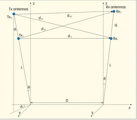
▲Figure 1.Tx antennas and Rx antennas in 2×2 LoSMIMOsystem.
Then,the eigenvalues of W are equal,and the optimal channelcapacity of 2×2 LoSMIMO can be achieved.
From(9)-(11),we obtain the principle of 2×2 LoSMIMO system for optimal channel capacity(Fig.2).
3 Factors Affecting the Channel Capacity of 2×2 LoS MIMO
Channel capacity of 2×2 LoSMIMO system is not optimal unless antenna spacing dtand dr,carrier wavelengthλ,one-hop distance D,and the angleθt,θrbetween antenna arrays and z axis(8).But in practical implementation,these factors do not satisfy(8)exactly and channel capacity is not optimal.
In this section,we discuss factors that affect LoSMIMO channel capacity of LoSMIMO in practical applications.These factors are:offset of hop distance D,offset of antenna spacing,Tx antenna and Rx antenna not on the same horizon,Tx and Rx antenna arrays are not on the same plane.
3.1 Offset of Hop Distance D
If the offset of hop distance D(D-offset)isΔand dt=dr(Fig.3),then

Substituting(13)into(5)and(3),we get the channel capacity within D-offset.We use a simulation to show how the D-offset affects channel capacity.
Fig.4 shows a comparison of optimalchannel capacity and channel capacity within D-offset(range[-1000 m,1000 m],interval 50 m)when carrier frequencyƒc=18 GHz,D=2000 m,θt=θr=0,and dt=dr,which satisfies(10).
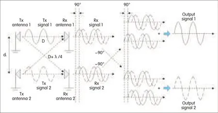
▲Figure 2.A 2×2 LoSMIMOsystem for optimalchannel capacity.
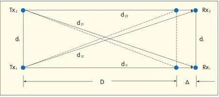
▲Figure 3.Offsetof one hop distance D in 2×2 LoSMIMOsystem.

▲Figure 4.Channelcapacity of optimal antenna parameters settings and antenna parameters settings within D-offsetin different SNR(from 10 dBto 60 dBand intervalis 10 dB).
The change of channel capacity corresponding to negative D-offset is larger than that corresponding to positive D-offset in[-1000 m,1000 m]and when ƒc=18 GHz.The larger the absolute value of the negative D-offset,the greater the difference of the channel capacity within D-offset from the optimal channel capacity.As the SNRincreases,this tendency becomes greater.
In practice,the D-offset factor,which influences channel capacity,should be applied during project implementation to reduce costs while maintaining
performance.
3.2 Offset of Antenna Spacing
In Fig.5,the offset of antenna spacing dt(dt-offset)isΔdtand dt=dr.Then,

Substituting(14)into(5)and(3),the channel capacity within dt-offset can be obtained.
We use a simulation to show how dt-offset influences channel capacity.Fig.6 shows a comparison of optimal channel capacity and channel capacity within dt-offset(range[-2 m,2 m],interval 0.1 m)when frequency ƒc=18 GHz,D=2000 m,θt=θr=0,and dt=dr=4.0825 m,which satisfies(10).
In Fig.6,whenƒc=18 GHz,D=2000 m,θt=θr=0,then the optimalantenna spacing dt=4.0825 m,which raises the question of practicality.If narrowing antenna spacing does not result in large loss of channel capacity away from the optimum channel capacity,it can be accepted.
The change of channelcapacity within the negative dt-offset is smaller than that within the positive dt-offset,and the difference in channel capacity within the negative dt-offset from the optimal channel capacity is acceptable when dt-offset is in the range[-1.5 m,0 m].As the SNR increases,this tendency becomes more apparent.This is conducive to antenna installation and only results in small loss from the optimal channel capacity.If the antenna spacing dtis 2.5 m,the channel capacity may be acceptable.
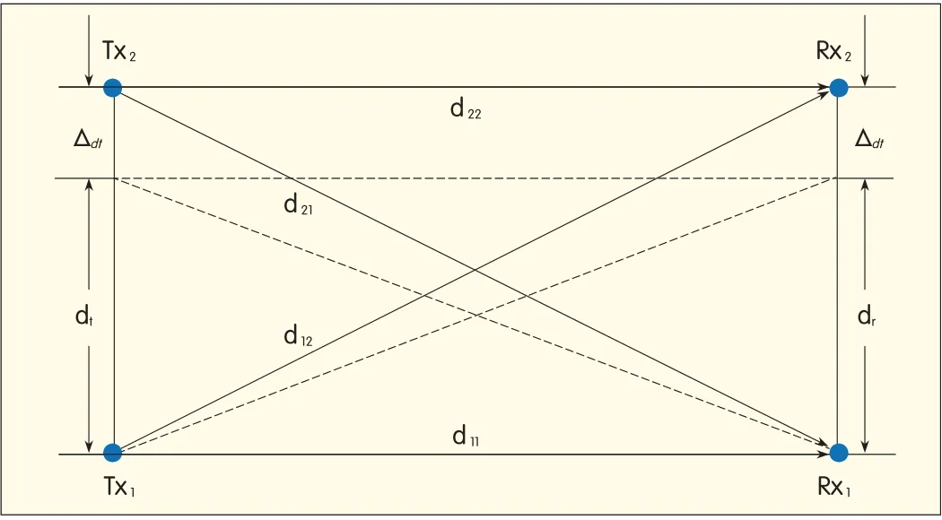
▲Figure 5.Offset of antenna spacing d t in 2×2 LoSMIMOsystem.
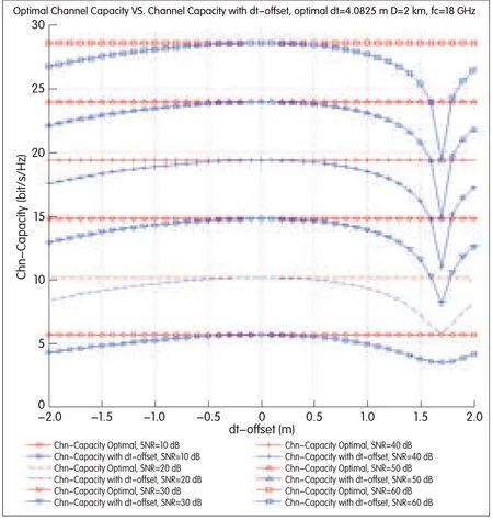
▲Figure 6.Channel capacity with optimalantenna parameters and antenna parameters within dt-offset in different SNR(10-60 dB,interval10 dB).
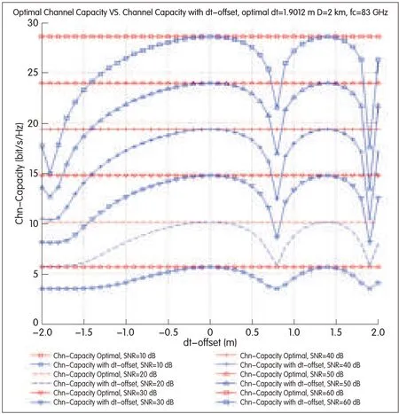
▲Figure 7.Channel capacity with optimalantenna parameters andantenna parameters within dt-offset in different SNR(10-60 dB,10 dB).
Fig.7 shows an enhancement on Fig.6.As carrier frequency increases,the required antenna spacing to achieve meaningful MIMO gain decreases,and the range of accepted dt-offset is smaller.The dt-offset range[-1.5 m,0 m]at 18 GHz may be acceptable,but at 83 GHz,only[-0.5 m,0 m]is acceptable.
Another case of unequal dtand dris also interesting;however,it will not be discussed here.Some conclusions can be drawn with similar analysis to the above.
3.3 Tx Antenna and Rx Antenna not on the Same Horizon
Without loss of generality,if we assume that the angle between horizontal line and line from Tx1to Rx1isγ,and dt=dr(Fig.8),then

Substituting(15)into(5)and(3),we can obtain channel capacity within angleγ.
We use a simulation to show how this factor influences channelcapacity.Fig.9 shows a comparison of optimal channel capacity and channel capacity within angleγ(range[-60°,60°],interval 5°)when frequencyƒc=18 GHz,D=2000 m,θt=θr=0,and dt=dr,which satisfies(10).The channel capacity within angleγ[-25°,25°]is almost optimal.This means that even if the ground is hilly,the system can work normally.
3.4 Tx Antenna Array and Rx Antenna Array not on the Same Plane
Without loss of generality,we can assume that
•the angle between the xz-plane and line from Tx1to Tx2isφt
•the angle between the projection of line Tx1to Tx2on the xz-plane and z-axis isθt
•the angle between the line from Rx1to Rx2and z-axis isθr
•dt=dr
•mast length is L(Fig.10).
Then,the coordinate of Tx1 is(xtx1,ytx1,ztx1)=(L cosφtsinθt,L sinφt,L cosφtcosθt)the coordinate of Tx2is
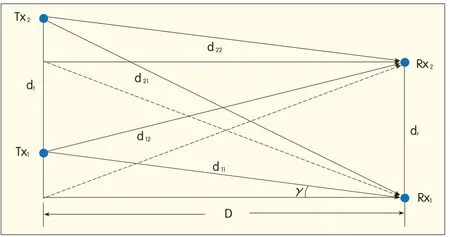
▲Figure 8.Tx antenna and Rx antenna are not on the same horizonin 2×2 LoSMIMOsystem.
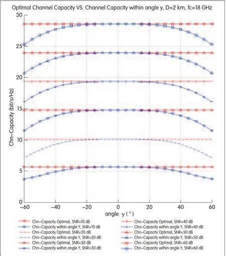
▲Figure 9.Channel capacity with optimal antenna parameters and antenna parameters with angleγ.
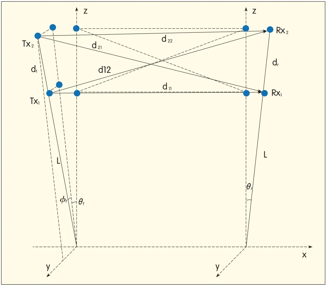
▲Figure 10.Tx antenna array and Rx antenna array are not on thesame plane in a 2×2 LoSMIMOsystem.


Substituting(16)into(5)and(3),we obtain the channel capacity within the factor of which Tx antenna array and Rx antenna array are not in the same plane.
We use a simulation to show how this factor influences channel capacity.Fig.11 shows a comparison of optimal

▲Figure 11.Channelcapacity with optimalantenna parametersand antenna parameters with angleφt.
channel capacity and channelcapacity within angleφt(range is[-90°,90°],interval is 5°)when frequencyƒc=18 GHz,D=2000 m,θt=θr=30°,L=15 m,and dt=dr,which satisfies(10).
Channel capacity is not very sensitive to the angle between the mast of the antenna array and z-axis,and this makes it easier to install the mast of the antenna array.The channel capacity within angleφt[-25°,25°]is almost optimal.This means that even if the ground is flat,the system can work normally,which is usefulfor practical antenna installation.
4 Conclusion
In this paper,we have discussed the principle of LoSMIMO and factors that affect LoSMIMO channel capacity.LoS MIMO performs wellin specific scenarios and improves transmission channel capacity.The simulation results show that LoSMIMO is not very sensitive to antenna parameters,and as long as these parameters do not differ too much from the optimal parameters,then there is only small loss of channel capacity,which is acceptable.This is useful for reducing costs in practical antenna installation without limiting performance.
LoSMIMO is relatively simple and easy to implement and should have good prospects.
eferences
[1]D.Tse and P.Viswanath,Fundamentals of Wireless Communication.Cambridge University Press,2005,p.294.
[2]E.Telatar,“Capacity of multi-antenna Gaussian channels,”in European Trans.Telecommunications,vol.10,no.6,Dec 1999,pp.585-595.
[3]I.Sarris and A.R.Nix,“Maximum MIMO Capacity in Line-of-Sight Sarris,”in Proc.5th Int.Conf.Information,Communications and Signal Processing(ICIS’05),Bangkok,Thailand,pp.1236-1240.
[4]T.Ingason and L.Haonan,Line-of-Sight MIMO for Microwave Links Adaptive Dual Polarized and Spatially Separated Systems,MSc Thesis in communications engineering,Department of Signals and Systems,Chalmers University of Technology,Göteborg,Sweden,July 2009,pp.27-30.
- ZTE Communications的其它文章
- Millimeter Wave Communication for Cellular and Cellular-802.11 Hybrid Networks
- Millimeter Wave and Terahertz Communications:Feasibility and Challenges
- WiGig and IEEE 802.11ad for Multi-Gigabyte-Per-Second WPAN and WLAN
- Modeling Human Blockers in Millimeter Wave Radio Links
- 60 GHz SIWSteerable Antenna Array in LTCC
- Terabit Superchannel Transmission:ANyquist-WDM Approach

