Millimeter Wave and Terahertz Communications:Feasibility and Challenges
Phil Pietraski ,David Britz ,Arnab Roy ,Ravi Pragada ,and Gregg Charlton
(1.InterDigital Communications LLC.,Melville,NY 11747,USA;
2.AT&T Labs,Shannon laboratories,Florham Park,NJ 07932,USA;
3.InterDigital Communications LLC.,King of Prussia,PA 19406,USA)
Abstract In this paper,the challenges with and motivations for developing millimeter wave and terahertz communications are described.Ahigh-level candidate architecture is presented,and use cases highlighting the potential applicability of high-frequency links are discussed.Mobility challenges at these higher frequencies are also discussed.Difficulties that arise as a result of high carrier frequencies and higher path loss can be overcome by practical,higher-gain antennas that have the added benefit of reducing intercellinterference.Simulation methodology and results are given.The results show that millimeter wave coverage is possible in large,outdoor spaces,and only a reasonable number of base stations are needed.Network throughput can exceed 25 Gbit/s,and cell-edge user throughput can reach approximately 100 Mbit/s.
Keyw ords millimeter wave;terahertz;small cells;propagation;mesh backhaul
1 Introduction
Today’s remarkably successful wireless infrastructure,services,and customer business models are largely derived from the realities,technology,and choices of spectrum made more than thirty years ago.Ironically,the cellular industry’s great technological revolution and market success may now be its undoing in the not-too-distant future.An emerging dichotomy between current infrastructure and bandwidth and surging customer services now begs the question:Will our existing wireless network spectrum and infrastructure be indefinitely scalable to support near-future consumer demands,needs,and services?
Moreover,are the current technologies and enhanced infrastructure,spectrum additions,and planned capacity enhancements enough to satisfy current and near-future network capacity requirements?In an analysis by Rysavy Research in 2010[1],the average demand per user was graphed against the average available network capacity per user.This analysis shows that average demand will irreversibly exceed capacity sometime in mid 2013,and the two curves will rapidly diverge thereafter.What is the long-term implication of this for customer service?
Beyond the traditional cellular and Wi-Fispectrum,which ends at around 6 GHz,there is another 294 GHz worth of FCC-defined spectrum.Within this 294 GHz span,there is an aggregation of roughly 200 GHz worth of fixed and mobile spectrum that today is largely unused.With suitable application of current and emerging technologies,a significant proportion of this enormous radio spectrum may be harvested within a decade to support multi-gigabit wireless mobile communications.Beyond this enormous FCC-defined spectrum is an additional unregulated,unlicensed radio spectrum known as the terahertz band.This spectrum band has channel sizes capable of supporting wireless data speeds of 10 Gbit/s to 100 Gbit/s and could offer an additional 300 GHz of spectrum for small-cellwireless mobile communications.
Growth in consumer data is outstripping the pace at which infrastructure can be deployed or invented to support it.Historically,demand for bandwidth in short-range wireless communications has doubled every 18 months.At this rate,demand willbe 800 MBper customer per day in less than 10 years.If,as expected,we see significant growth in wireless machine-to-machine(M2M)communications and services,wireless communications as we know it will be irreversibly changed.As customers begin to demand ubiquitous gigabit and multi-gigabit services,fundamentally new and disruptive technologies and architectures willbe required.
AT&Treports that its data traffic associated with smart phones(especially iPhones)has increased 8000%in the last four years,and global sales of smart phones and other cell phones is starting to flatten,particularly in the USand Europe.Almost every human being on the planet now owns(or has access to)a cell phone,smart phone,or dongle.The amount of data used by each person is skyrocketing,and it is predicted that each user will require 14 Gbit/s by 2016.By 2020,daily use of personalmobile broadband and dongles willexceed 800 MB.By 2020,we will require approximately 130 exabits(1018)of data per year.
The FCC is now describing this period of unparalleled growth in smart phone data and wireless network use as a“looming spectrum crisis.”In response,service providers have increased the demand for wireless capacity by deploying more spectrum-efficient technologies and taking more spectrum-efficient approaches.They are also lobbying to expand spectrum coverage from 300 to 3000 MHz to support anticipated near-future capacity needs.
Service providers are now deploying 3G and 4G cellular technologies to enhance wireless network capacity.These new higher-capacity cellular systems use microcells,LTE,femtocells,and sectored and smart antenna technologies that are designed to more efficiently use existing cellular spectrum.The new technologies significantly(but still incrementally)improve network capacity and are rapidly approaching the Shannon Limit.There is little room left to squeeze any more capacity out of available cellular frequencies.
These infrastructure fixes do little to improve network capacity for the anticipated surges in wireless data demand.Adding marginally more efficient infrastructure to the same cellular spectrum bands will do little to satisfy the anticipated long-term demand for wireless data capacity.In this context,we suggest an alternative approach that takes advantage of millimeter wave frequencies.
2 Use Cases and Applications
In essence,a small-cell/nanocell is simply a superhigh-capacity wireless transport pipe.Here,we describe some use cases.
Large public spaces tend to have large gatherings of people working,engaging in conversation,and involved in common activities or events.
With easy cellular communications,there may be many people talking on cellphones and sharing data.Such environments may be plazas,parks,shopping areas,theaters,or stadiums.Although in the near term the data and voice traffic of an individualuser might be relatively low-volume,a small cell covering only part of a public space might struggle to handle the aggregated traffic of a conglomeration of users.Such a scenario might be a concert or sporting event where a large number of people are simultaneously using wireless terminals to download video and pictures.
By using concatenated,self-organizing small cells and adaptive frequency tiling in the public space,a large amount of user data can be supported,even in peak periods.Concatenated smallcells can forward and route high-peak traffic between the small-cellnodes and different network points-of-presence(PoPs)to avoid capacity limitations at a small-cell-to-network connection.Flexible deployment of millimeter wave backhaul allows small cells to be deployed so that system performance and customer connectivity can be optimized.The small-cell configuration does not have to be restricted by its proximity to a network optical fiber.
Stadiums have become increasingly spectrum-challenged in recent years,and operators have been forced to use a multitude of technologies to provide wireless services at major events.Highly directional millimeter wave frequency bands would provide super-high capacity links within a stadium to route in-stadium traffic between small-cell and Wi-Fi modules.They would also provide fiber-free connectivity to and from the stadium.These high frequencies would not interfere with existing radio and cellular communication within the stadium.They would dramatically increase data transport capacity within and around the stadium but not impinge on existing services and capacity-stretched cellular and Wi-Fi bands.
Perhaps the most valuable applications for millimeter wave and terahertz technologies willbe in dense urban and business locations,especially where tall buildings create deep street canyons.In such locations,cellular service is often very limited and/or unreliable.
Traditional approaches to cellular transmission and relatively wide spacing between cell tower placements constrain system performance in these scenarios.The problem is further compounded by large numbers of mobile cellphone users moving around at street level and by greatly varying demand loads.
Densely backhauled small cells,and eventually nanocells,are being developed to address this street-canyon condition.Aseries of 3G,4G,LTE,and Wi-Fi-capable low-powered small cells are deployed on a street(preferably mounted on existing powered street poles).The small cells are connected to each other for traffic and network management,and their concatenated chain is backhauled to and from the network PoPby optical fiber,high-capacity millimeter wave and terahertz radio,or a cost-effective combination of these.
Directed millimeter,terahertz,and optical methods for small-cell backhaul are well-suited to capitalize on high frequencies and street-level light-pole-to-light-pole geometries.
Growth in the number of cellphones worldwide is beginning to flatten out,but daily subscriber wireless traffic(mobile broadband)will increase 500%to 294 MB per day by 2020[2],[3].Wireless data associated with dongles will increase by 1000%to 503 MBby 2020[3].In addition,the emergence of resident or intelligent cloud-based agents will add a new human-to-machine data capacity requirement and,beyond this,pure machine-to-machine wireless network data transfer.Large cloud data farms will increasingly engage with the real world via sensor and ad hoc networks,and transfer vast amounts of data over high-speed opticaland wireless networks.
Existing cellular and Wi-Fiinfrastructure along with spectrum allocations will not have the capacity to support long-term mass data transport requirements.New network topologies will be required,perhaps to separate voice and small-data services from big-data services with the latter being routed in a new high-capacity wireless layer—the nanocell.This high-capacity wireless layer builds on the previously discussed small-cell infrastructure,making use similar fiber and self-aligning highly directed millimeter wave beams to backhaulbetween the network and nanocells.Rather than using limited-capacity cellular and Wi-Fi spectrum to connect the mobile customer to the network,the nanocellsteers a highly directional high-frequency beam to the nearby customer for the short timeframe in which the the data is transsferred.Studies show that such high-capacity wireless links could provide 50-100 Gbit/s backhaul and throughput to the customer[4].
3 Challenges With Millimeter Wave and Terahertz Propagation
3.1 Free Space Path Loss
Small cells allow a network planner to take advantage of shorter distances between the cells.These shorter distances provide greater opportunity for line of sight;there is more available power(street furniture);and there is greater opportunity to use high-data-carrying millimeter wave,terahertz,and optical frequencies(FSOC).However,nature increasingly limits the transmission distances of these higher frequencies.Ironically,natural limitations on transmission may make these higher frequencies ideal for inter-small-cell backhaul and relaying because they minimize spectrum overflow between small cells and allow greater spectrum reuse.Higher frequencies are increasingly scattered and or blocked by molecules in the atmosphere,and this loss must be accounted for in an intercell and end-to-end link budget.
Propagation losses at millimeter wave and terahertz frequencies are considered too large for practical communication in large networks that involve links of more than a few tens of meters.The dependency of the free-space path loss can be clearly seen in the well-known equation
Equation(1)shows that just by moving from a 2 GHz carrier to a 60 GHz carrier(a popular unlicensed millimeter wave band),the path loss increases by nearly 30 d B.This sounds disastrous for millimeter waves and terahertz,but first the assumptions in and derivation of the equation should be considered.
If we assume the transmit antenna radiates isotropically,then the power density(measured in W/m2)of the plane wave at the receive antenna at distance d from the transmit antenna is

There is no additional path loss at higher frequencies in terms of the power density versus distance.If the transmit antenna is permitted to have gain,for example,using directional antennas,the received power collected by the receive antenna is

where GTis the gain of the transmit antenna,and A is the effective aperture of the receive antenna.So far,there is no dependency on the carrier frequency;the dependence is embedded in A,which is proportional to the square of the wavelength.In other words,by going to much higher frequencies,our antennas also become smaller,and A also becomes smaller.The effective aperture can be written as

where GRis the gain of the receive antenna,andλis the wavelength.The received power can then be written as

For simple antenna structures,GTand GRare generally not very large and do not depend on frequency;therefore,the received power decreases rapidly as the carrier frequency increases.However,a more practical constraint on antennas might also include the physical size of the antenna.We consider our antennas to be phased arrays of smallantenna elements.The physical size of an array is fixed as the carrier frequency changes.If we consider the arrays to be uniform and rectangular,the number of elements that can be placed in a given area is 1/λ2.In this alternative view,phased arrays of fixed size are used to create narrow beams at the transmitter and receiver,and there is an additionalgain proportional to the number of antenna elements in each array.The received power can now be written as

where GTand GRare the gains of each antenna element,and C is a constant depending on the chosen fixed area.The key thing to notice is thatλ2is now in the denominator.In(6),increased carrier frequency is an advantage not a disadvantage.This may be an optimistic view,but there is no free space path loss for higher frequencies if advanced antenna architectures,such as phased arrays,are used.
3.2 Atmospheric Absorption
Atmospheric absorption is also often cited as a reason that millimeter wave and terahertz communications are impractical.Atmospheric absorption in much of the millimeter wave and terahertz spectrum is much higher than that of conventional cellular spectrum.This should,however,be seen in context.Atraditional macro cellmay have to cover link distances of several kilometers.At these distances,gaseous water and molecular oxygen absorption(terrestrial)can be prohibitive.The unlicensed 60 GHz band is intentionally positioned at an oxygen absorption line,and this results in approximately 15 d B/km attenuation.This is a big loss at macro celldistances,but for smallcells,the loss is quite manageable in terms of link budget.For example,if a circular cell needed to have a coverage distance of 150 m,the worst-case gaseous absorption loss at 60 GHz is only 2.25 d B.The gaseous absorption drops off at higher frequencies and remains below 15 d B/km until the water line is encountered at about 160 GHz.Although atmospheric absorption reduces received power,it has a benefit in the form of higher signal-to-interference ratio(SIR).Desirable signals generally emanate from base stations physically closer to the intended receiver;undesirable signals(interference)generally emanate from base stations that are further away.Thus,SIRis improved.
Rainfall is also often cited as a reason that millimeter wave and terahertz communications are impractical.However,the same argument regarding small cells and gaseous absorption can be made.The comparatively short link distances mean that loss from rainfall is tolerable most of the time.A 25 mm/h rainfall(heavy rainfall)could cause about 10 d B/km additional loss.At 50 mm/h,the loss is about 20 d B/km.In New York,rainfall greater than 50 mm/h occurs only 0.01%of the time and is short-lived[5].With only 3 d B extra margin,a system in New York with 150 m links has 99.99%protection against rainfall.Fig.1 shows the atmospheric absorption at sea level for different rates of rainfalland for oxygen and water vapor a 7.5 g/m3.
3.3 Diffraction and Penetration Loss
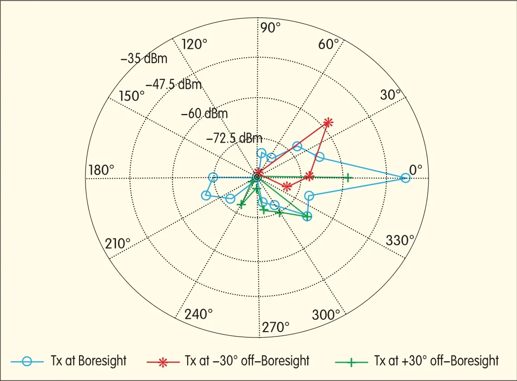
Diffraction and penetration loss are arguably the main problems with millimeter wave and terahertz communication.Diffraction properties are almost optical,and many common building materials are almost opaque to millimeter wave and terahertz signals.This makes the channel highly specular,and such a channel is sometimes referred to as a“billiard”channel because of the occasional need to make a bank shot to get around an impenetrable obstruction(Fig.2).

▲Figure 1.Atmospheric absorption at sea level.
For very high performance,links should be LoSor require a small number of reflections.Fortunately,small cell architectures and electrically steerable narrowbeam antennas can help mitigate many problems.Small cells are more likely to be serving mobiles that are reachable using either LoS transmission or a single reflection.Electrically steerable narrowbeam antennas are responsive and can quickly switch to unobstructed paths.
3.4 Waveforms and Multiple Access Schemes
Wide bandwidth;high-gain,narrowbeam antennas;and cost-effective electrically steered antennas influence the choice of waveform and multiple access schemes.We make the following observations:•An advantage of the millimeter wave spectrum,with its large available bandwidths,is that there is less need for high spectral efficiency.Simple modulations may be appropriate.
•Wider bandwidths and higher data rates are also beneficial in that lower transmit power can be used to achieve the same capacity as a smaller bandwidth channel.
•Narrowbeam transmission implies that fewer mobiles are illuminated by a particular transmission.Although interference is reduced by the spatial containment of signals,narrowbeam transmission limits the possibility to serve more than one mobile with a single beam.The potential advantage of frequency domain scheduling is therefore limited(assuming RFbeamforming is used),and this reduces the need for multicarrier waveforms.The lower peak-to-average power ratio(PAPR)of single-carrier waveforms is also more attractive for low-cost electronics.
•Narrowbeam transmission also implies mobiles may be spatially separated and serviced simultaneously using spatial division multiple access(SDMA)techniques.However,SDMA would require multiple RFand baseband processing chains,which initially may be cost prohibitive.A reasonable system might therefore have wide bandwidth,a simple low-PAPRwaveform with low-order modulation,and TDMA access schemes.
▲Figure 2.Specular channels.
4 Regulation
The International Telecommunication Union(ITU)is the main telecommunications regulatory body in the world and coordinates the shared global use of radio spectrum.There are also severalorganizations with national jurisdiction to regulate spectrum.In the US,the Federal Communications Commission(FCC)regulates spectrum according to Title 47(Telecommunications)of the Code of Federal Regulations(CFR).In Europe,spectrum is regulated by the European Conference of Postal and Telecommunications Administrations(CEPT)according to reports prepared by the Electronics Communications Committee(ECC)and European Radio Communications Committee(ERC)and according to standards formulated by the European Telecommunications Standards Institute(ETSI).In China,the Bureau of Radio Regulation under the Ministry of Industry and Information Technology regulates spectrum.In this section,regulatory issues concerning frequencies in the millimeter wave band are outlined.
4.1 Unlicensed Spectrum
Unlicensed spectrum has predefined rules for both hardware and radio deployment so that interference is mitigated by the technical rules defined for the band rather than being restricted for use by entities through a spectrum licensing approach.The industrial,scientific,and medical(ISM)frequency bands are unlicensed and allow both communicating and non-communicating devices to operate.Co-channel interference from a non-communicating device can therefore affect performance of communication networks operating in such bands.However,the 60 GHz band is largely free of non-communicating devices(except on a small set of frequencies from 61 to 61.5 GHz,which is an ISM band),and because of this,the variety of potential interferers is greatly reduced.
4.2 Unlicensed Millimeter Wave Spectrum
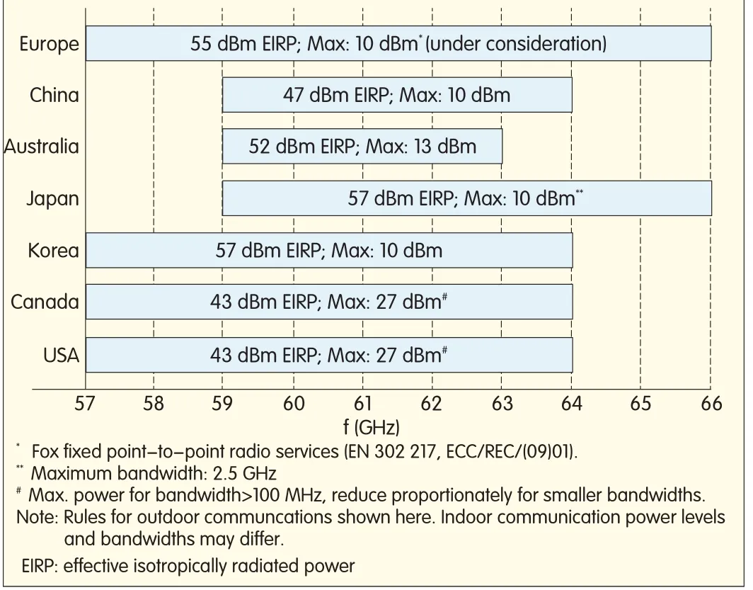
Unlicenced operations on the 57-64 GHz band in the US(referred to as the 60 GHz band)are regulated by Title 47,Part 15 of the CFR(47 CFR 15).The regulations of 47 CFR 15 and the significant absorption of the 60 GHz band by atmospheric oxygen makes this band better suited for short-range point-to-point and point-to-multipoint applications.Fig.3 shows the main regulatory provisions of the 60 GHz band in various countries.In response to a representation made by the Wireless Communications Association(WCA)in 2007,the FCC introduced a proposal seeking to change 60 GHz transmission rules[6],[7].
Table 1 summarizes the transmit power and antenna requirements for the 60 GHz band in the USand Europe.In a millimeter wave system that supplements a cellular network,an electronically steerable phase-array antenna is required to satisfy the minimum antenna gain specified in the regulations and to support user mobility.To conform to different regional specifications,antennas of different sizes and containing tens of elements may be required.Also,because the beams from these antennas have limited steerability,multiple arrays may be needed,especially at the base station,to provide omnidirectional coverage.
▲Figure 3.Regulatory overview of the 60 GHz band in various countries.
4.3 Other Bands of Interest
4.3.1 The 70,80 and 90 GHz(E/W)Bands
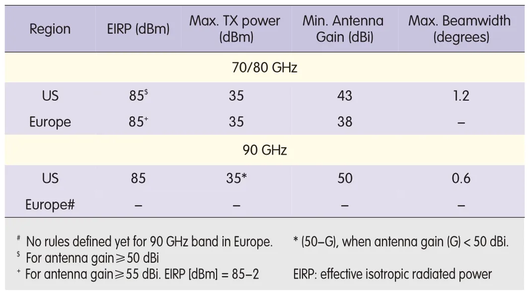
Table 2 summarizes the transmit power and antenna requirements for the 70,80,and 90 GHz bands in the USand Europe.Existing E-band point-to-point links are essentially static because they use parabolic dish antennas to satisfy theopportunities exist in the higher millimeter wave band.There are atmospheric absorption windows at 140 GHz and 240 GHz that avoid the absorption peaks at 119 GHz,183 GHz,and 325 GHz.In these bands,there is sufficient spectrum to allocate 40 GHz of bandwidth from 125 to 165 GHz and 100 GHz of bandwidth from 200 to 300 GHz.To use this band,fragmented allocations must be consolidated and service rules must be framed while avoiding frequencies meant for passive services.There is a ten-year timeframe for new service rules once a motion has been introduced at an ITU WRC.regulatory requirements on antenna gain and beamwidth.Such antennas make network planning expensive and affect scalability.To make a network truly scalable,an electronically steerable phased-array antenna is required.This allows a transceiver using a single antenna array to dynamically steer the beam in the desired direction of another nanocell node.However,in order to meet regulatory requirements on antennas,a fairly large antenna array is required,and this drives up technological challenges and costs.

▼Table 1.Regulatory requirements on power and antennafor 60 GHz band
▼Table 2.Regulatory power and antenna requirements for 70,80and 90 GHz bands
4.3.2 Low Millimeter Wave Bands
There are also millimeter wave bands of interest below 60 GHz,but these tend to have smaller bandwidths(Table 3).
4.3.3 High Millimeter Wave Bands
To achieve even higher capacity and data rates,
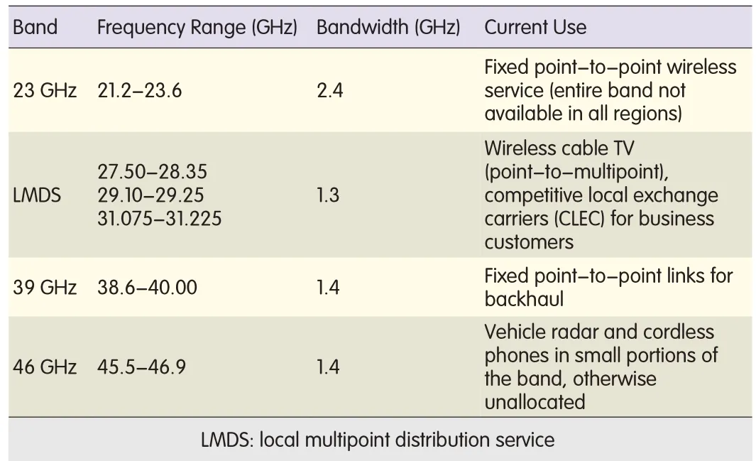
▼Table 3.Millimeter wave frequency bands of interest
4.4 Radio Frequency Radiation Exposure Limits
The possible health implications of human exposure to radio frequency electromagnetic(RFEM)fields have led to output power of radio transmitters being regulated.Millimeter wave frequencies are absorbed by moisture in the human body and cannot penetrate the outer layers of skin.Exposure to millimeter wave radiation must not exceed the maximum permissible exposure(MPE).The current MPEfor 1.5-100 GHz is 1 mW/cm2,measured at a minimum distance of 5 cm from the radiating surface.Fig.3 shows the minimum required separation between a human body and radiating surface to comply with MPEat 60 GHz.The minimum separation for the maximum permissible EIRPfor USand Europe are marked in Fig.4.Antenna design and placement are crucial to MPEcompliance in user devices.
5 High-Level System Architecture
If millimeter wave and terahertz frequencies are introduced into a cellular system,new architectural elements need to have superhigh capacity and permit connectivity with highly directional beams.An existing cellular system,such as an LTE system,provides adequate coverage,security,and reliability and is a good framework upon which a millimeter wave or terahertz layer can be added.Essentially,this is a new heterogeneous nanocell layer for 5G radio networks.All controlsignaling—including system information,idle-mode mobility,paging,random-access channel(RACH)access,radio resource control(RRC)and nonaccess stratum(NAS)signaling(signaling radio bearers),and multicast traffic—is provided via the existing cellular layer.The millimeter wave/terahertz layer provides high throughput for offloading traffic from the existing cellular bands below 6 GHz.
The proposed layered architecture with cellular overlay and millimeter wave/terahertz underlay as shown in Fig.5.It provides a clear evolutionary path by building on existingcellular/4G architectures using carrier aggregation,which was introduced in 3GPPRelease 10.The millimeter wave architecture introduces two new nodes:a millimeter wave base station(mB)nanocell and a millimeter wave gateway(mGW).The mB primarily has millimeter wave/terahertz access links to mobiles and millimeter wave/terahertz backhaul(BH)links to other mBs and the cellular base station(eNB).However,wired connections are also possible.The mBs are expected to perform millimeter wave and terahertz physical-layer functions and possibly certain MAC-layer functions.
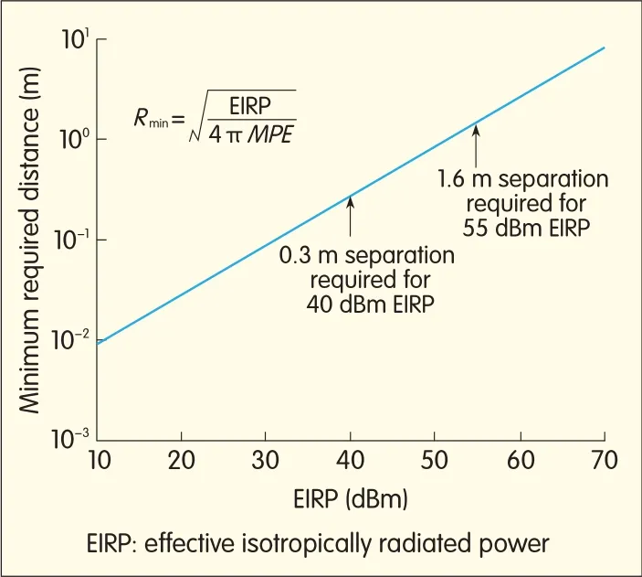
Figure 4.▶Minimum distance tobe maintained between a human body and radiatingsurface for MPEcompliance.
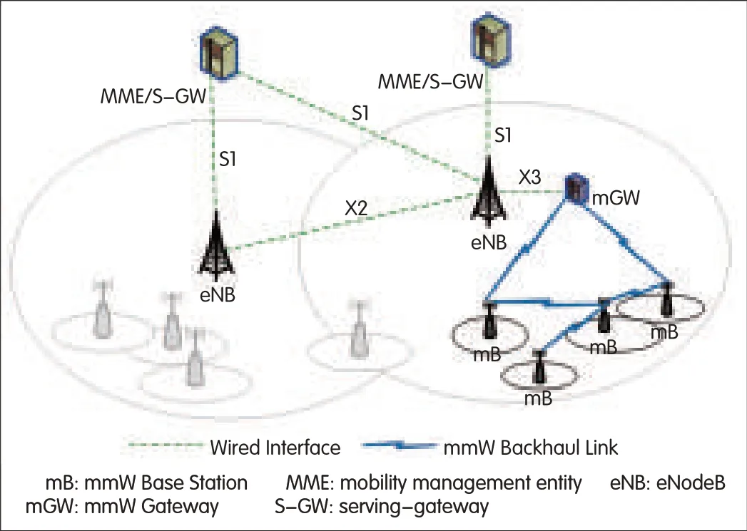
▲Figure 5.Tiered architecture.
Apart from super-channel data processing,where the millimeter wave/terahertz link has high throughput,an mB is also expected to perform scheduling-related functions for millimeter and terahertz frequencies assigned to the mB by the eNB.To relieve the eNBof data processing and routing of user data that is carried on the millimeter wave layer,another logical node called millimeter wave gateway(mGW)node is introduced.The mGWis responsible for routing and processing user data carried over the millimeter wave overlay.This processing is done on the higher-layer access stratum(AS).An important motivation for introducing the mGWnode is to support a large number of mBs in a scalable manner.This relieves the load on the eNB and provides an additional data pipe from the mBs to the evolved packet core(EPC).New network(logical)components,such as selective frequency-routing devices,are likely necessary.These frequency-routing devices are designed to separate out in real time the high data traffic from the lower-bandwidth cellular traffic.The high data traffic is routed to the superchannel.This avoids frequent hand-off overhead for control-plane bearers and low-throughput traffic.
Mesh backhaul is valuable for the architecture because it increases deployment options and flexibility.Wired backhaul coverage can be scarce or cost-prohibitive.The backhaul links between mBs form a multihop mesh network,and long backhaul links are not required.This reduces capex and increases backhaul reliability by providing multiple routes.The high directionality of the millimeter wave/terahertz beam also allows the same spectrum to be used for both access and self-backhaul in the millimeter wave/terahertz layer.
For millimeter wave and terahertz technology to be widely accepted,it is imperative that mBcapex and opex are low.Self-configuration,self-optimization,and self-healing are crucial to cheap mB deployment.Outdoor mB units must be small,lightweight,and“belt-able”for easy installation.They can be mounted on existing street lampposts and do not require air-conditioning or indoor housing.Because they have low energy needs,power-over-Ethernet(PoE)feeding or even local harvesting,for example,solar,may be used.Typically,mBs would be mounted on lampposts six meters or higher above the ground.At this height,there are fewer obstacles to interfere with propagation.For newly deployed mBs,an eNB can provide initial system configuration and may assist in the configuration of backhaul links with neighboring mBs.A new mB may also use information from neighboring mBs in a docitive manner in order to determine and configure the initialset of system parameters for its operation.
5.1 UE Perspective
Amillimeter-wave-enabled UEfirst needs to connect to the cellular layer before it can connect to the millimeter wave/terahertz underlay layer.Fig.6 shows how UEs obtain millimeter wave/terahertz connectivity.The eNB coordinates with the corresponding mBthat the UEconnects to.At power on,and with successful camping on cellular layer,the UE switches to idle mode and connects to the eNB.The eNB,after considering the mBs involved,will determine a suitable mB for the UEto connect to and will provide the specific millimeter wave configuration information to the UEvia RRC procedures.Once the UEis finished with millimeter wave/terahertz services,it can switch to idle mode(if it is not using any cellular underlay services)or it can switch to connected mode(where only cellular underlay services are used and the millimeter wave layer is deleted).
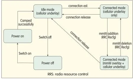
▲Figure 6.Millimeter wave layer connectivity atthe UE.
6 Mobility Challenges
The directional nature of the millimeter wave link introduces mobility challenges that are unique to the millimeter wave/terahertz layer.To effectively use highly directional beams and lock onto and track the mobile user,highly directional antennas with beam steering and tracking capabilities are crucial.Traditional hand-off mechanisms need to be reassessed because of the near LoSand high directional requirements of millimeter wave links.Even when the user changes direction or orientation,hand-off procedures may be triggered.New mechanisms to reduce association and/or synchronization time with the target mB(s)need to be developed.
To alleviate hand-off issues,several new mechanisms need to be developed,and this involves significant changes to architecture.A possible solution is to separate control-plane and user-plane functionality between the eNB and mBs.With this approach,control-plane and higher-layer data-plane protocols,including radio link control(RLC)and packet data convergence protocol(PDCP),run at the eNB.Such an architecture can be easily built to coexist with the architecture proposed in section 5.This approach minimizes data loss caused by mobility.The RLC layer is stillterminated at the eNB because window-based mechanisms,such as ARQ,and buffering mechanisms are typically implemented in the RLC layer.One benefit of this approach is that security and ciphering/integrity algorithms are executed at the eNB,and this eases the burden on mBs by eliminating the need for ciphering and/or trust-zone features.
As the size of the nanocells shrink,another alternative is to have nanocells work in cooperative clusters.They can be designed to hand-off and forward customer data traffic between themselves and the next sequential group of nanocells(clusters)surrounding the customer as they move sequentially through the nanocells.This cooperative“moving”of concatenated nanocell clusters at the network edge differs from the existing method of routing and hand-off decisions at the local Central Office or deeper within the network.Because of their small coverage,these individual nanocells do not have enough time to route customer traffic through traditional circuits for hand-off decisions.They require such decisions to be executed locally within the network edge and nanocell clusters.This is the intelligent edge model.
7 Simulations
System simulations were conducted to determine the feasibility of outdoor millimeter wave/terahertz coverage.The system simulator comprises two main modules.One is a commercially available cell-planning toolused by a number of European operators.WINPROP,from AWE Communications,makes detailed propagation predictions based on ray tracing and takes transmit antenna patterns into account.This allows accurate,static multipath channel models to be created between each transmitter and receiver pair.WINPROPdetermines the delay,signalstrength,AoA,and AoD.If they occur,it also determines the types of interactions(for example,LoS,reflection,and diffraction)for each path arriving at a user-defined point.The other main module introduces time-varying elements,such as fading and scheduling,into the simulations and is written in MATLAB.This module creates channelmodels based on WINPROP data.It estimates the throughput of each UEin the system by modeling the impact of factors such as transmit power,interference,receive antenna patterns,and schedulers.The statistics are then collated to give an estimate of overall network performance.
Transmit antenna patterns are generated for the mBphased array antennas and are used in the ray-tracing simulation.We assume a 7×7,49 element uniform rectangular array(URA)and classical beamforming.Each URAis limited to cover 90°(±45°)in azimuth;that is,four arrays are used to achieve 360°coverage.Such an antenna provides a gain of 25.9 d Biwith 20°beamwidth at broadside.The result is an overall transmit EIRPof 40 d Bm perpendicular to the array.
The deployment was located in the central area of a large,public university(Fig.7).Five mBs were deployed around the quadrangle—one in each corner and one in the middle.
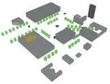
Figure 7.▶3Dview of collegecampus.
Because ray tracing is used,the RFproperties of the building materials must be characterized in order to capture transmission loss,reflection loss,and diffraction loss.At the simulated carrier frequency of 60 GHz,diffraction is typically insignificant,but penetration and reflection loss must be taken into account.Simulation assumptions are given below for a variety of building materials.In the campus scenario,all buildings are assumed to have concrete walls of typical thickness,have building penetration loss of 19 d B,and have reflection loss of 14 d B[8].
The simulation assumptions are:
•50 UEs per drop
•10 drops
•1000 time samples(TTIs)
•60 GHz carrier frequency with 2 GHz bandwidth
•modulation limited to QPSK
•round robin scheduling
•each mB array chooses from one of three beam directions(all at 0°elevation),and each beam corresponds to 7×7 URA
•Omni UEantenna
•6 d Bnoise figure
•5 mBs
•40 d Bm EIRP
•4 m mBheight with 1.5 m UEheight•Rician fading per path
•full buffer traffic.
The intent is to determine the feasibility of a relatively uncomplicated millimeter wave system,so complex schedulers,interference coordination,and directional receive beams are not used.Accordingly,simple QPSKmodulation with round robin scheduling is assumed.The number of UEs per drop is 50 and corresponds to a 10%activity factor for a UEdensity of 8000 UE/km2.The 40 d Bm EIRPlevel is consistent with FCC regulations.
Fig.8 shows the RFcoverage in the campus deployment.The yellow regions correspond to received power levels greater than-60 d Bm,and the green regions correspond to received power levels between-70 d Bm and-60 d Bm.There are twelve separate beams because there are four arrays in the center mB and there are three possible beam directions from each array.Only one of these three beams in an array is active in any TTI.These levels are considered sufficient to support the lowest MCSclass imposed by standards such as 802.11ad.The received power is adequate across most of the central quadrangle indicating that,when properly deployed,millimeter wave technology can serve outdoor users with very high data rates.Building edges and vegetation are obstacles to millimeter wave service.
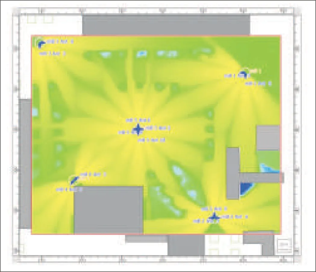
▲Figure 8.Coverage plot for central campus area.
Fig.9 shows the CDFfor user throughput,and Fig.10 shows the total throughput.Approximately 95%of the UEs receive millimeter wave links,and the mean throughput is 500 Mbit/s,which is very large.In practice,the overlay LTE network is used to service the 5%of UEs that cannot receive millimeter wave links.Because the LTEnetwork is so lightly loaded,these UEs should still receive good service.Moreover,the throughput at the millimeter wave cell edge(10th percentile)is approximately 100 Mbit/s,and the median total throughput for the campus network is 32 Gbit/s.These figures provide some numerical context to the coverage plot shown in Fig.8.The discrepancy between the megabyte-per-second cell-edge user throughput and the gigabyte-per-second network throughput is due to the fact that there are 50 active users with a median user throughput of 500 Mbit/s.This equates to a network throughput on the order of 25 Gbit/s.
The campus could be covered by a 3.5 GHz picocell network;however,such a system would be constrained to 100 MHz bandwidth,and the necessary spectral efficiency to match the proposed millimeter wave network would have to be about 20 times greater.A combination of greater spectral efficiency and many more 3.5 GHz pico base stations could be used to achieve the same end,but such super-dense deployments should be avoided.
When human beings block the propagation paths between the transmitter and receiver,there is a significant increase in path loss and a corresponding loss in throughput.Human blockage comes in two forms that have statistically different mechanisms:self-blockage by the user(highly related to UE location)and blockage by other humans in the area(not related to UE).Adetailed description of this phenomenon and its effect on network and individual user performance is given in[9].The authors of[9]used a statistical human blockage model to study the effect population density on throughput.The factors affecting blocking probability were population density,Tx-Rx distance,and Tx-Rx height difference.Fig.11 shows the effect of human blocking for different population densities[9].It was shown that using a pair of directional antennas in the receiver improves performance over omnidirectional receive antennas.Apair of directional antennas has a good chance of being able to point a high-gain beam at at least one reflected path,thus recovering much of the performance lost by blocking of the LoSpath.Of course,some UEs are still foced out of coverge.
8 Conclusion

▲Figure 9.User throughput.

▲Figure 10.Total cellthroughput.
The challenges of and motivations for developing millimeter wave and terahertz communications have been presented.A high-levelcandidate architecture was also described.Use cases have been enumerated,and the potentialapplicability of high-frequency links in these cases has been explained.Although the path loss caused by millimeter wave and terahertz signals is significant,additional antenna gain at these wavelengths can overcome the problem,and there is even an additional benefit of reduced intercell interference.
Last,a feasibility study on 60 GHz access links on a college campus was presented.The results show that millimeter wave coverage is feasible in a large,public area,and only a limited number of base stations are required.Additionally,the 95%of users who were covered by millimeter wave links enjoy very high throughput.However,the effect of human blockage can be quite severe,reducing network throughput by about 10%when the density of humans was approximately one person per 10 m2.Arguably,this is a reasonable density to assume on campus.Using a pair of directional receive antennas restores much of the loss caused by human blocking.
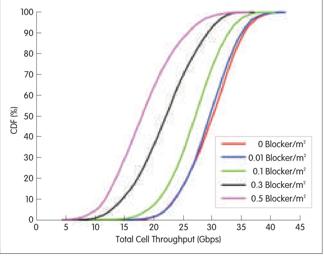
▲Figure 11.Network throughput as a function of blocker density.
- ZTE Communications的其它文章
- Millimeter Wave Communication for Cellular and Cellular-802.11 Hybrid Networks
- WiGig and IEEE 802.11ad for Multi-Gigabyte-Per-Second WPAN and WLAN
- Modeling Human Blockers in Millimeter Wave Radio Links
- 60 GHz SIWSteerable Antenna Array in LTCC
- Line-of-Sight MIMOfor Next-Generation Microwave Transmission Systems
- Terabit Superchannel Transmission:ANyquist-WDM Approach

