Modeling Human Blockers in Millimeter Wave Radio Links
Jonathan S.Lu,Daniel Steinbach,Patrick Cabrol,and Philip Pietraski
(InterDigital Communications,LLC,Melville,NY,11747,USA)
Abstract The loss from multiple human blockers is empirically and analytically investigated at millimeter wave frequencies.Humans are modeled as absorbing screens of infinite height with two knife-edges,while physical optics is used to compute the contribution from rays diffracting around them.This model is validated with blocking gain measurements of multiple human blocking configurations on an indoor link.The blocking gains predicted from physical optics have good agreement with measurements ranging from-50 d Bto 2.7 d B,making the absorbing screen model suitable for real human blockers.Mean and standared deviation of prediction error are approximately-1.2 and 5 d B,respectively.
Keyw ords 60 GHz;diffraction;human blocking loss;human shadowing;indoor environment;millimeter wave propagation;physical optics
1 Introduction
I n millimeter wave systems with access links to mobile users,humans are likely blockers of the radio links.This is particularly true in shopping malls,at store fronts,and in airports.Past works describe how humans can cause severe fades,that is,losses greater than 20 d B[1],[2].Therefore,it is critical to include the effect of human blockers in simulations.Here,we focus on modeling and computing human blocking(shadowing)for a millimeter wave radio link.
Transmission loss caused by human blockers is very high at millimeter wave frequencies,and transmission is virtually opaque.Therefore,diffraction around human blockers and reflection and scattering by nearby objects or structures significantly affects the received power.Millimeter wave systems that include link distances greater than a few meters typically use highly directional antennas or arrays in order to overcome path loss incurred at high frequencies.Thus,the reflection and scattering by surrounding objects away from the direct line between the transmitter and receiver is greatly attenuated by the antenna patterns or array beamforming patterns.We investigate and modelthe diffraction around human blockers.
The exact electromagnetic characteristics of human bodies are not described in the literature.In previous works,researchers have attempted to model the electromagnetic properties of humans at millimeter wave frequencies.Human bodies have previously been modeled as absorbing screens[3],[4];water phantoms[5];cylinders[6],[7];and rectangular prisms[8].These models were validated only for a single human blocker;however,to the best of our knowledge,they have not been validated for multiple human blockers.Furthermore,in previous simulations,the affect of multiple human blocking on the radio environment has been determined through geometric optics,for example,ray-tracing.However,in geometric optics,geometric theory of diffraction(GTD)and uniform theory of diffraction(UTD)do not have higher-order diffraction terms and are not valid for multiple blockers located in each other’s transition regions[9].Therefore,other approaches,such as physical optics,are recommended.Both geometric and physical optics are approximate techniques.Full-wave solutions using numerical techniques such as finite-difference time domain,finite element,and method of moments are computationally infeasible because of the small millimeter wavelength.
In some millimeter wave scenarios,the transmitting and receiving antennas are positioned low relative to the heights of the human blockers so that the predominant diffractions travel around the human blockers rather than over them.This scenario is the focus of this work.We propose using physical optics to compute the received field around the human blockers.In physical optics,points in space where there are wave fields may be considered elementary sources of radiation whose amplitudes are proportionalto the amplitudes of the fields at those points.Here,we model human blockers as absorbing screens of infinite height with two knife edges similar to those in[10](Fig.1).This model is computationally favorable,and if sufficiently accurate,is preferable to more complex models for rapidly simulating the radio channel.In physical optics,the received field can be expressed in the form of multiple integrals,which we numerically evaluate using Piazzi’s numerical integration method[11]-[13].The predicted blocking gain from the diffracted fields is then computed using the coherent sum of fields and incoherent sum of powers.The predictions are compared with the measurements of various one-,two-and three-person blocking configurations.Here,the blocking gain is the ratio of received power with blockers to received power without blockers.Assuming there are negligible reflections from the ground and nearby objects,the blocking gain is equivalent to the ratio of received power to free-space power.
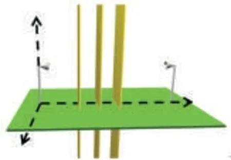
◀Figure 1.Multiple blockersmodeled as absorbing screens of infiniteheight.
2 Piazzi Physical Optics Method
We model the human blockers as absorbing screens of infinite height and with two vertical knife edges(Fig.1).To compute diffraction gain,(the ratio of diffracted power to free-space power)from an arbitrary number of screens,we use a physical optics method developed by Piazzi[11]to treat diffraction past multiple absorbing screens with knife-edges.The code used to evaluate multiple knife-edge diffractions is based on the same principles of physicaloptics used in[14]-[16].We assume that a)the knife-edges are of infinite length and are parallel,and b)the additional diffraction gain for a point source on a plane that is perpendicular to the screens is the same as that for a line source that is parallel to the screens and intersects the plane at the source point.
With these assumptions,the physicaloptics description of diffraction around an absorbing screen is expressed as multiple integrations in the x-z planes containing the absorbing screens.The integrations in the coordinate along a z-plane knife-edge can be approximated analytically so that we are left with integration in the x-coordinate away from the knife-edges.This is seen in the following expression for the magnetic field H(xn+1,yn+1)in the plane containing the n+1 absorbing screen[12]:

whereρis the distance from the secondary source point(xn,yn)on plane x=xnto receiver point(xn+1,yn+1)on plane x=xn+1,and k is the free-space wave number.The field on plane x=xncontaining the n th screen is given by H(xn,yn).To arrive at an expression with multiple integrals,we substitute H(xn,yn)in(1)with H(xn-1,yn-1),which is the field on plane x=xn-1 containing the n-1 screen and can similarly be written in integral form.
To predict diffraction gain from multiple screens,the integrals must be carried out numerically.The integral in(1)must be terminated with finite upper and lower limits(for the right and left sides of the screen),and the integration must be replaced by a discrete summation.An abrupt termination of the integral is equivalent to placing an absorbing screen outside the termination point and would artificially generate diffracted waves that are not part of the actual problem.In[15]and[16],quadratic approximations are used for the amplitude and phase of the integrands over intervals of less than one wavelength in order to discretize the integrals.Spurious diffraction was removed by using asymptotic approximations to analytically evaluate the integral outside the termination points of the numerical analysis.This allowed for larger intervals,but an additional cost was necessary to evaluate the complex error functions.In contrast,the Piazzi method involves simple linear approximations of the amplitude and phase and introduces a smoothing procedure that uses a Kaiser-Bessel function to terminate the integration without introducing spurious diffraction[11]-[13].
We compare the blocking gain found by using the Piazzi method with the time-averaged gain measurement for a given blocker configuration.To compute the complex field for each diffracted path,the previously mentioned integrals are separated.In Fig.1,there are three absorbing screens with two edges each,and there are 23=8 forward diffracted paths.The gain for the diffracted path that travels along the x+sides of the screens is found by assuming that all screens are semi-infinite and have knife-edges located at x+edges.This is equivalent to setting the lower x limit of each integral to the position of the x+edges.
Human blockers in the test setup inadvertently move slightly between measurements,and these movements are reflected in the measurements.The movements are slight relative to the distances of the blockers from the transmitting and receiving antennas.Therefore,the amplitude of the field of each diffracted path can be assumed to be constant.However,the exact phase of each path cannot be known because a)these inadvertent movements cause path length differences on the order of or greater than the 5 mm wavelength at 60 GHz,and b)the exact electromagnetic interactions with the human body cannot be known.Depending on the configuration of blockers,a particular measurement may be inaccurate because of the movements.If we assume these movements are sufficient to obtain a well-mixed sample of possible phases,the time-averaged gain measurements can be approximated by assuming the phases of the different diffracted contributions are uncorrelated,uniform,random variables.Thus,the time-averaged diffraction gain can be modeled as the sum of the incoherent powers of gains from the different paths.Conversely,if we assume the phases are not random,the diffraction gain found by coherently summing the complex magnetic fields is equivalent to not separating the previously mentioned integrals.Small,inadvertent movements may not be sufficient to produce well-mixed averages,and we could expect some hybrid model to provide more accurate predictions.
3 Measurements
3.1 Setup
Fig.2 shows our 60 GHz measurement setup.On the transmit side,the R&S®SMF100Amicrowave signal generator provides a 10 GHz sine wave to the R&S®SMZ90 frequency multiplier,which multiplies the frequency by six.The resulting 60 GHz signalthen travels through a straight section waveguide to a V-band horn antenna with 24 d Biof gain and 7 degree 3 d B beamwidth.The level of the radiated signal can be adjusted via a 25 d B mechanically controlled attenuator included in the multiplier assembly.
The signal is received with an identical horn antenna that is connected to the N12-3387 low noise amplifier(LNA)with a straight waveguide section.The amplified signal is sent to the FS-Z90 harmonic mixer where it is down-converted and captured on the FSQ26 vector signalanalyzer(VSA).
3.2 Measurement Procedure
The majority of human blocking cases involved three blockers at most[3].Therefore,we took measurements at 60 GHz for one,two and three blockers.Using the setup previously mentioned and the Cartesian coordinate system in Figs.1 and 3,the transmitting and receiving antennas were placed 7 m apart and at a height of 1 m.The coordinates of the transmitting antenna were(0,0,1)and those of the receiving antenna were(0,7,1).The environment was an empty 8×10 m conference room.The reflections from the walls were heavily attenuated by the antenna patterns,longer path length,and reflection loss.The receiving antenna primarily measured the gain for propagation paths going through and around the blockers.
To measure gain in a one-person blocking scenario,a 43.2 cm wide blocker was placed halfway between the antennas.The blocker moved perpendicular to the direct line between the antennas(y-axis,Figs.1 and 3),and measurements were taken at intervals of either 5 cm or 10 cm depending on how close the blocker was to the direct line.In the two-person scenario,45.7 cm wide blockers were 1 m.These comparisons are qualitatively similar to measurements where blockers have non-constant separation,because changing the blocker separation only
change the diffraction angles.Our measurements consider a wide range of diffraction angles as shown in Fig.3.spaced 1 m apart halfway between the antennas.The first blocker had four positions,and the second blocker had six positions.In the three-person scenario,blockers were also spaced 1 m apart halfway between the antennas.The first blocker was 48.2 cm wide and had three positions;the second and third blockers were 45.7 cm wide and had five positions.The positions of the blockers in the two-and three-person scenarios were chosen so that the line of sight(LoS)was almost always blocked,and practical blocking scenarios were considered(Fig.3).These positions are listed in Table 1.The received powers for all possible blocking configurations in the two-and three-person scenarios were recorded.To maintain consistency,the blockers were centered over their positions and stood with their arms at their sides,facing the receiving antenna.
Five measurements were recorded for each blocking configuration in all scenarios.The blocking gain was then computed using the ratio of measured power with blockers to measured power without blockers.To determine the time-averaged blocking gain,the blocking gains were averaged over the five measurements.
Note that the physical optics predictions are compared with measurements where blockers have a constant separation of
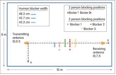
▲Figure 3.Two-and three-person blocking positions(to scale)in an 8×10 m room.
4 Results and Analyses
In this section,we discuss variability in the measurements taken with various blocker configurations and compare these measurements with the diffraction gains predicted using the Piazzi method and incoherent-power-sum approach in section 2.

▲Figure 2.60 GHz Human Blocking Measurement Setup
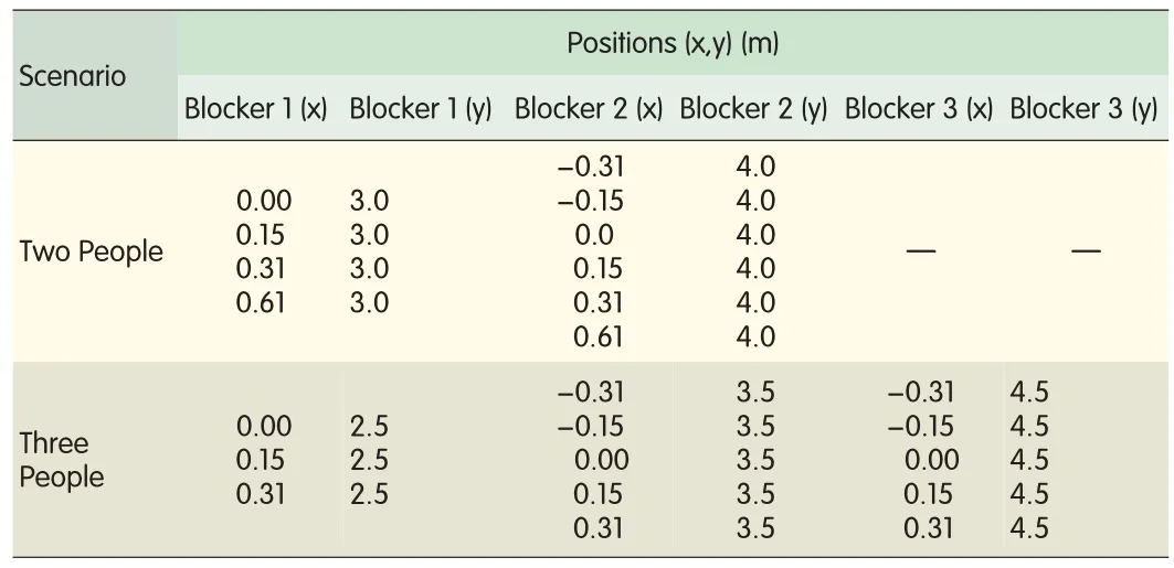
▼Table 1.Blocker positions using the Cartesian coordinate system of Fig.1
4.1 Measurement Variability
Because the blockers inadvertently moved,variability was introduced into the received signal for a given blocker configuration.The time-averaged blocking gain captured and averaged these movements.Because the ranges of blocker movements are unknown,we compare the time-averaged measurements with the blocking gains predicted using both the Piazzimethod and incoherent-power-sum approach.When the blockers moved only slightly,the measurements are expected to more closely match those of the Piazzimethod.When there was a greater range of movement by the blockers,the measurements are expected to more closely match the blocking gain predicted using the incoherent-power-sum approach.However,because of the limited number of measurements taken for each configuration,deviations are expected.
4.2 One-Person Blocking
Fig.4 shows the measurements taken for a one-person blocking scenario.The blocking gains predicted using the Piazzimethod and incoherent-power-sum approach are also shown.From Fig.4,the sum of incoherent powers agrees fairly well with the measurements and has a maximum deviation of 4.7 d B.The measurements also agree with the predictions of the Piazzimethod for different blocker positions.When the blocker’s center location x coordinate is less than 0 m,the measurements fall on the Piazzicurve.When the blocker is located at(0,3.5)in Figs.1 and 3,x=0.When the blocker’s center location x coordinate is greater than 0 m,the measurements are slightly offset from the Piazzi curve.The reason for this may be that the blocker was not properly centered,and the blocker’s effective width was actually less than 43.2 cm.These results suggest that the absorbing screens also model the phase information of a human blocker at millimeter frequencies relatively well.
To compare with[3],we also plotted the worst-case and best-case blocking gains(computed with UTD)from a direct ray and two diffracted rays[12].The blocking gain from the direct ray is-∞d B when the blocker obscures the LOSand 0 d B when the blocker does not obscure the LoS.The worst-case scenario is found by assuming the secondary contributions are 180 degrees out of phase with the dominant contribution.Conversely,the best-case scenario assumes that allcontributions are in phase.The measurements mostly fall between the worst-case and best-case curves.Because the physical optics solution and UTD are nearly identicalwhen only one screen is present,the physicaloptics solution lies in between the best-case and worst-case curves.The rapid variation of the Piazzicurve suggests a simplified model for human blocking.In such a model,approximate positions are used to compute the mean incoherent-power-sum gain,and the slight movements of humans are captured as a random variable with an appropriate distribution.
4.3 Blocking by Multiple People
Figs.5 and 6 show the time-averaged blocking gain measurements for two-and three-person scenarios(in increasing order).The predicted blocking gain from Piazzi method and incoherent-power-sum appraoch are also plotted.Depending on the configuration in the two-and three-person blocking scenarios,there can be deep fades in the measurements when the blocking gain is less than-30 d B.The blocking gain in all scenarios ranges from 2.7 d B to-50.7 d B.This range is much larger than those in[1]and[2]and further justifies the need to include human blocking models in channel simulators.
Figs.7 and 8 show the errors in the predictions made using the Piazzimethod and incoherent-power-sum approach for two-and three-person blocking scenarios.A prediction error is the predicted blocking gain minus the time-averaged blocking gain.Table 2 shows the mean and standard deviations of the prediction error using the Piazzimethod and incoherent-power-sum approach.The Piazzimethod has a smaller mean error but larger standard deviation compared with the incoherent-power-sum approach.This is to be expected because of uncertainty in the exact location of the blockers and time-averaging done in the measurements.We also determined the percentage of configurations with prediction error between±5 d B.The percentage of configurations exceeding 5 d B error for the Piazzimethod was 75%in a two-person scenario and 68%in a three-person scenario.The percentage of configurations exceeding 5 d B error for the incoherent-power-sum approach was 83%in a two-person and 68%in a three-person scenario.
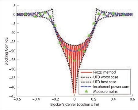
▲Figure 4.Comparison of one-person blocking gain measurements with blocking gain predicted using the Piazzimethod,incoherent-power-sum approach,and UTD.

▲Figure 5.Comparison of two-person blocking gain measurements with blocking gain predicted by Piazzimethod and incoherent-power-sum approach for blocker positions listed in Table 1.
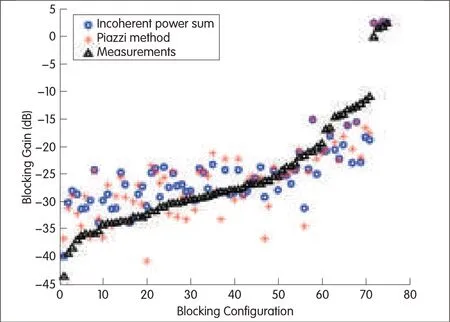
▲Figure 6.Comparison of three-person blocking gain measurements with blocking gain predicted by Piazzimethod and incoherent-power-sum approach for blocker positions listed in Table 1.
The majority of configurations with high blocking loss typically have negative prediction errors.High blocking loss mat be caused by large diffraction angles.This suggests that another model,for example,a cylinder model,may better predict diffraction around blockers at large diffraction angles.However,from the standard deviation,we conclude that an absorbing-screen model is sufficient to compute blocking gain in most applications.
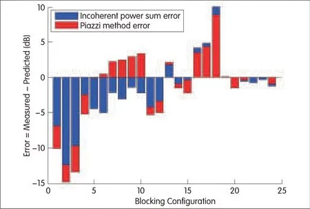
▲Figure 7.Error of blocking gain predicted using the incoherent-power-sum approach and Piazzimethod for two-person scenario with blocker positions listed in Table 1.

▲Figure 8.Error of blocking gain predicted using the incoherent-power-sum approach and Piazzimethod for three-person scenario with blocker positions listed in Table 1.

▼Table 2.Prediction error statistics over all configurations for two and three people blocking scenarios
In Fig.5,the spans of the two-person blocking measurements are also plotted.The lower limit of each bar is the minimum blocking gain for a blocker configuration,and the upper limit is the maximum blocking gain.Because only five measurements were taken per configuration,the possible span is likely larger.In Fig.5,most of the blocking configurations with a span larger than 10 d B have blocking gain less than-30 d B and have larger prediction errors.The variability and large negative gains could be caused by the constructive and destructive interference of the various diffracted paths and the uncertainty in the exact position and movements of the blockers.Thus,we should expect that in these configurations,the Rician K-factor is small.The Rician K-factor is the power ratio of the dominant arrival(path with the greatest received power)to all other arrivals.It is a metric that is negatively correlated with the level crossing rate and positively correlated with the fading depth of the received field[17].From the predicted powers of the two person blocking configurations,the computed K-factors are all less than 2 d B,which is small.However,the majority of the three-person blocking configurations have predicted K-factors greater than 10 d B.The large predicted K-factor in the three-person blocking scenarios may allude to some other significant multipath that we have not considered.
5 Conclusion
We have treated multiple human blockers as absorbing screens of infinite height to create a model for computing blocking gain in 60 GHz links.The model agrees well with one-,two-and three-person blocking-gain measurements in the range of 2.7 d B to-50 d B.In a few select cases with large incoherent-sum blocking gain of less than-30 d B,the predicted errors are greater than 5 d B.Coupled with a large predicted Rician K-factor,this alludes to the presence of un-accounted for multipath and/or the need for more accurate models of human blockers at large diffraction angles.However,our comparisons with the measurements show that our model is sufficient for determining the impact of multiple blocking humans.
For deterministic system-level simulations of the millimeter wave radio channel,the Piazzimethod can be used in conjunction with a ray-tracing simulator to determine the gain experienced by paths blocked by humans.However,in scenarios with human blockers,a statistical component in the model is preferred because it is often impractical to include the slight movements of humans in a simulation.In such scenarios,we propose the incoherent-power-sum approach coupled with a random variable to predict the gain on paths blocked by humans.This random variable is dependent on the exact complex fields of the various multipaths and the movement of the blockers.Further research needs to be done on the statisticalnature of this random variable.
Acknowledgements
The authors wish to express their gratitude and appreciation to Dr.Henry L.Bertoniof Polytechnic Institute of New York University for his helpful insights and comments on millimeter wave propagation.
- ZTE Communications的其它文章
- 2013 IET International Conference on Information and Communications Technologies
- ZTELaunches the First PC-Based CPTfor LTENetworks
- ZTECommunications Guidelines for Authors
- ZTELaunches Innovative Energy-Saving Solution for LTENetworks
- Design and Implementation of ZTE Object Storage System
- Hierarchical Template Matching for Robust Visual Tracking with Severe Occlusions

