Study of the Prediction of the Engine’s Underwater Exhaust Noise
WANG Xiao-qiang,LOU Jing-jun,LI Hua,WU Hai-ping,ZHU Shi-jian
(1 College of Naval Architecture and Power,Naval University of Engineering,Wuhan 430033,China;
2 Dalian Navy Academy,Dalian 116018,China)
Study of the Prediction of the Engine’s Underwater Exhaust Noise
WANG Xiao-qiang1,LOU Jing-jun1,LI Hua2,WU Hai-ping1,ZHU Shi-jian1
(1 College of Naval Architecture and Power,Naval University of Engineering,Wuhan 430033,China;
2 Dalian Navy Academy,Dalian 116018,China)
The generation mechanism and radiation characteristics of the engine’s underwater exhaust noise are complicated due to gas water two phase flow.In this paper,the engine’s underwater exhaust noise is predicted numerically based on the Mixture multiphase flow model,the RNG κ-ε turbulence model and the Ffowcs Williams-Hawkings acoustic model.Meanwhile,the engine’s underwater exhaust noise is measured based on the designed test rig.Comparison between the predicted underwater exhaust noise and the measured one shows that the proposed numerical method for the prediction of the engine’s underwater exhaust noise is feasible in engineering.
engine;underwater exhaust;noise prediction;numerical simulation;experiment
Biography:WANG Xiao-qiang(1982-),male,Ph.D.student of Naval University of Engineering,E-mail:wxq_nue@126.com.
1 Introduction
The generation mechanism and radiation characteristics of engine’s underwater exhaust noise are complicated and the related theory is not mature yet because the discharge process is involved with the gas water two phase flow.And the previous researches on this problem rely heavily on experiments[1-9],which are expensive and complex.The engine’s underwater exhaust noise caused by exhaust pressure pulsation,a monopole sound source,can be predicted accurately by the existing theoretical model,however,the dipole source noise formed by the interaction between the fluid and walls,the quadrupole source noise caused by turbulence and the influence of the water spay in the exhaust pipe on the underwater exhaust noise can not be predicted yet.Therefore,it is necessary to further strengthen the research on related theory and simulation of the engine’s underwater exhaust noise and its control technology.
The engine’s underwater exhaust noise is predicted based on the Mixture model,the RNG κ-ε turbulence model and the Ffowcs Williams-Hawkings(FW-H)acoustic model and the simulation results are verified by the experiment.
2 Mathematical formulations
The procedure for computing engine’s underwater exhaust noise consists largely of two steps.In the first step,a time-accurate flow solution is generated using the Mixture model and the RNG κ-ε turbulence model,from which time histories of pressure on the selected source surface are obtained.In the second step,sound pressure signals at the specified receiver location are computed using the source data collected during the first step and the FW-H model,which is applicable to predict the propagation of sound toward free space.
2.1 Governing equations
2.1.1 The mixture model
The mixture model is a simplified multiphase model that can be used to model multiphase flows where the phases move at different velocities,but assume local equilibrium over short spatial length scales.The coupling between the phases should be strong.It can also be used to model homogeneous multiphase flows with very strong coupling and the phases moving at the same velocity.The mixture model can model n phases(fluid or particulate)by solving the momentum,continuity,and energy equations for the mixture,the volume fraction equations for the secondary phases,and algebraic expressions for the relative velocities[10].
The continuity equation for the mixture is:

The momentum equation can be expressed as:

where n is the number of phases,is a body force, μmis the viscosity of the mixture,vdr,lis the drift velocity for secondary phase l,and αlis the volume fraction of phase l.
The energy equation for the mixture takes the following form:

where keffis the effective conductivity,SEincludes any other volumetric heat sources.
The relative velocity(also referred to as the slip velocity)is defined as the velocity of a secondary phase(p ) relative to the velocity of the primary phase(q):

The drift velocity and the relative velocity)are connected by the following expression:

From the continuity equation for secondary phase p,the volume fraction equation for secondary phase p can be obtained:

2.1.2 The RNG κ-ε turbulence model
The turbulence kinetic energy κ,and its rate of dissipation ε,are obtained from the following transport equations[11]:

In these equations,Gkrepresents the generation of turbulence kinetic energy due to the mean velocity gradients.Gbis the generation of turbulence kinetic energy due to buoyancy.YMrepresents the contribution of the fluctuating dilatation in compressible turbulence to the overall dissipation rate.The quantities αkand αεare the inverse effective Prandtl numbers for κ and ε,respectively.
2.2 The Ffowcs Williams and Hawkings model
The FW-H equation was derived by Ffowcs Williams and Hawkings in 1969 to compute the sound caused by the interaction between the solid boundaries of any movement and fluid using Lighthill acoustic analogy and the theory of generalized functions.A more generalized FW-H equation was derived by Frances Antonio in 1997 by combining Kirchhoff equations and the FW-H equation,which not only has the accuracy of the FW-H equation,but also retains the advantages of Kirchhoff formulas in calculating the total aerodynamic noise.FW-H equation is an accurate sound field equation for monopole,dipole and quadrupole noise prediction,which is formed by reordering the Navier-Stokes equations in the form of the wave equation,meets the wave equations even if the integration surface is in the nonlinear region,and therefore has better adaptability.FW-H equation has been widely successful in the recent decades of application,and is recognized as one of the theoretical basis of the aeroacoustics,in particular,the aerodynamic noise prediction.
The FW-H equation is essentially an inhomogeneous wave equation that can be derived by manipulating the continuity equation and the Navier-Stokes equations.The FW-H equation can be written as[11]:


3 Numerical research
In this section the engine’s underwater exhaust flow field is simulated using the Mixture multiphase flow model and the RNG κ-ε turbulence model when the exhaust back pressure is 0.115MPa and the engine speed is 1 900r/min.Based on the simulation results of the flow field,the engine’s underwater exhaust noise is simulated using the FW-H model.The computational domain of the simulation model contains the exhaust pipe and its external water space,and the state parameters of the exhaust gas of a single-cylinder engine under the operating condition are set as the relevant boundary conditions.
3.1 Numerical model and boundary conditions
The three-dimensional two-phase flow field calculation region is shown in Fig.1.The exhaust pipe nozzle(Fig.2)is a cylindrical pipe without any appendages.The exhaust pipe is 1.8m long in the vertical direction,the center of the pipe exit is 1.4m below the water surface and the nozzle diameter D=0.03m.The cylindrical area(The diameter is 40D,and the length is 75D)is occupied by water initially,while the boundaries are set as pressure outlet except that the surface in the left side is set as wall.Orthogonal hexahedral grids are used in the flow field calculation with the jet nozzle and the vicinity of the jet axis encrypted with more dense grids.The turbulent boundary layer is established on the wall of the pipe to fully consider the impact of the wall on turbulence.The whole computational domain is discretized into about 935 748 control volumes by hexahedral cells,which is determined by the grid-independent study.The inlet of the exhaust pipe is set as pressure inlet,and the value of the pressure is defined by UDF,which equals to that of the exhaust gas of the engine under the operating condition.The density of the gas at the inlet is set as constant and the gas temperature is set to 473.15K.The pressure at the pressure outlet is equal to the sum of the local atmospheric pressure and the water pressure at the location and is also defined by UDF.The mathematical model is solved using finite volume method.To ensure the convergence of the solution,the SIMPLE pressure-velocity coupling equation is used for pressure correction,and the equations such as the momentum equation,the turbulence equation,the energy equation and the volume fraction equations are discretized with the first-order upwind theme.First-order implicit time scheme is adopted and the time step of the unsteady calculation is set to 1e-3s.
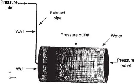
Fig.1 Grid of the computational area and boundary conditions

Fig.2 Grid of the exhaust pipe exit
3.2 Numerical results
3.2.1 Flow field
As is shown in the contours of the static pressure and the velocity magnitude of the vertical profile along the axis of the exhaust pipe at 5.25s(Figs.3~4),the pressure gradient and the velocity gradient are much larger in the vicinity of the exhaust nozzle,and therefore the vicinity of the exhaust nozzle can be regarded as the main sound source area.Fig.5 and Fig.6 show the time history of the static pressure and the spectrum characteristics of the pressure pulsation at the measuring point respectively.As is shown in Fig.6,the frequencies of the main peak of the pressure pulsation are equal to the engine’s firing frequency(15.8Hz)and its higher harmonics.And thus it can be concluded that the pressure pulsation of the two phase exhaust flow field and that of the gas in the exhaust pipe are closely related.

Fig.3 Contours of static pressure at 5.25s(Pa)
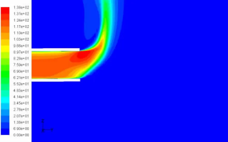
Fig.4 Contours of velocity magnitude at 5.25s(m/s)
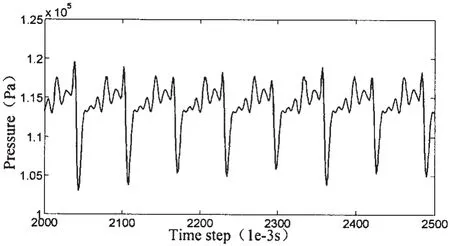
Fig.5 Time history of the static pressure at the measuring point

Fig.6 Spectrum characteristics of the pressure pulsation at the measuring point
3.2.2 Sound field
Based on the converged simulation results of the unsteady two-phase flow field,the engine’s underwater exhaust noise is simulated using the FW-H model.A permeable cylindrical surface in the vicinity of the exhaust nozzle is selected as the sound source surface,which surrounds the major sound sources.And the diameter is 10D and the length is 20D.The time step(Δt ) is set to 0.001s in consideration of the computational expenses.As the maximum fre-quency of the predicted noise(fM)is limited by the time step fM=1/(2·Δt),the maximum frequency of the predicted noise is 500Hz.The reference sound pressure is set to 1μPa,the farfield velocity 1 500m/s,the far-field density 1 000kg/m3.An observation point is arranged,and the coordinate is(1.25,3.165,-1.7).
Fig.7 shows the sound pressure level spectrum of the underwater exhaust noise at the observation point.It can be seen from the figure that there are many line spectrum whose frequencies are the engine’s firing frequency(15.8Hz)and its higher harmonics.The sound pressure level at the firing frequency is 152.1dB,which is the highest in the studied frequency range.And the predicted total sound pressure level is 155.9dB.
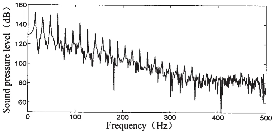
Fig.7 Predicted underwater exhaust noise at the monitoring point
4 Test and validation
To facilitate the comparison between the simulation results and the test data,and thus evaluate the accuracy of the methods for the prediction of the engine’s underwater exhaust flow field and the underwater exhaust noise proposed in section 3,the test rig and test procedures are designed combing with the relevant parameters of the simulation model to ensure the test conditions consistent with the simulation conditions.The test system includes:the gas supply system,the anechoic water tank and the data acquisition and processing system.The gas supply system is to provide the high-temperature pulsative gas source necessary for the test.It consists of the diesel generator set,the exhaust pipe,vibration isolators,simple acoustic enclosures,and etc.Anechoic pool can reduce the interference of the reverberation of the pool with the noise measurement,and thus can make the measured underwater exhaust noise value closer to that in the environment of free sound field.And therefore the anechoic pool is used in the experiment.The main function of the data acquisition and processing system is to measure and record the state parameters in the test.The main components include the data acquisition system,the hydrophones,the pressure sensors,the thermocouples,the flow meters,the speed sensor,the pressure gauges and etc(see Fig.8).Data acquisition system is the PXI-1042Q data acquisition system using the NI PXI-4472 board.The data acquisition program for the test of the engine’s underwater exhaust noise is developed on LabVIEW,a virtual instrument platform of National Instruments.The RHS-30-type hydrophones and the EWCT-312M-1.7BARA transient-type water-cooled pressure sensors produced by Kulite are used in the test.

Fig.8 Sketch of experimental system for the engine’s underwater exhaust noise
The underwater exhaust noise is measured at the same observation point when the engine runs under the similar operating condition comparing with the simulation.By comparing the measured and the predicted underwater exhaust noise level spectrum(Fig.9)at the observation point,it can be found that there are significant similarities.The measured and the predicted noise both have line spectrum at the engine’s firing frequency(15.8Hz)and its higher harmonics and the sound pressure levels are both the highest at the firing frequency in the studied frequency range.At the firing frequency,the predicted sound pressure level is 152.1dB,the measured sound pressure level is 155.4dB,and the difference is 3.3dB.In the studied frequency range,the predicted total sound pressure level is 155.9dB,the measured total sound pressure level is 158.6dB,and the difference is 2.7dB.In the higher frequency range,the difference between the predicted value and the measured data is larger.
Taking into account the errors of the predicted results and the measured ones,the proposed method for the prediction of the engine’s underwater exhaust noise is feasible in engineering.
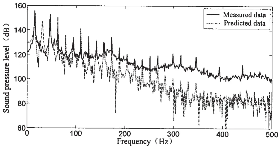
Fig.9 Predicted and measured underwater exhaust noise at the monitoring point
5 Conclusions
The engine’s underwater exhaust noise is predicted numerically based on the Mixture multiphase flow model,the RNG κ-ε turbulence model and the Ffowcs Williams-Hawkings acoustic model.And the proposed numerical method is verified by the experiment.Comparison between the predicted underwater exhaust noise and the measured one shows that the simulation results and experimental results are basically the same.Although there are some differences,the proposed numerical method for the prediction of the engine’s underwater exhaust noise can be regarded as feasible in engineering by taking into account the errors of the simulation model and the experiment.And the previous researches on this problem rely heavily on experiments,which are expensive and complex.Therefore the proposed underwater exhaust flow field and noise prediction method can be used for the underwater exhaust noise reduction to shorten the design cycle and reduce the research costs.
[1]Fang Kaixiang.A study on the submerged exhaust noise generated from an oscillating disk heat engine[J].Shipbuilding of China,1995(3):80-86.
[2]Zhang Wenping,Ma Qiang,Zhang Zhihua,et al.The ways to attenuate and the factors to affect noise generated from submerged exhaust of a diesel engine[J].Journal of Harbin Shipbuilding Engineering Institute,1991,12(4):406-413.
[3]Zhang Wenping.Experimental and theoretical studies of submerged exhaust noise from diesel engine[D].Harbin:Harbin Shipbuilding Engineering Institute,1992.
[4]Zhang Wenping,Ma Qiang,Zhang Zhihua,et al.Noise radiated from the submerged exhaust exit of diesel engine[J].Journal of Harbin Shipbuilding Engineering Institute,1993,14(2):25-33.
[5]Zhang Wenping,Ma Qiang,Zhang Zhihua,et al.Experimental studies of submerged exhaust noise from diesel engine[J].Chinese Internal Combustion Engine Engineering,1994,15(2):52-56,62.
[6]Zhang Wenping.The characteristics analysis and control of the exhaust noise of an underwater exhaust submarine[R].China Shipbuilding Technology Report,1995.
[7]Zhang Wenping,Zhang Zhihua,Ma Qiang.A boundary model of submerged exhaust exit of diesel engine[J].Transactions of CSICE,1996,14(2):188-194.
[8]Zhang Wenping,Zhang Tianyun,Liu Zhigang,et al.The two-phase flow pattern of submerged exhaust of diesel engine[J].Chinese Internal Combustion Engine Engineering,1996,17(3):14-18.
[9]Zhang Jianhua,Li Jian.Experimental researches of submerged exhaust noise from diesel engine[J].Wuhan Shipbuilding,1995(1):16-21.
[10]Zhou Junjie,Xu Guoquan,Zhang Huajun.FLUENT engineering and case analysis[M].Beijing:China Water Power Press,2010:464-466.
[11]Fluent.Inc.Fluent 6.3 user’s guide[K].2006.
发动机水下排气噪声预报研究
王晓强1,楼京俊1,李 华2,吴海平1,朱石坚1
(1海军工程大学 船舶与动力学院,武汉 430033;2海军大连舰艇学院,辽宁 大连116018)
由于涉及到两相流,所以发动机水下排气噪声的产生机理和辐射特性非常复杂。文章基于Mixture多相流模型、RNG κ-ε湍流模型和Ffowcs Williams-Hawking声学模型对发动机水下排气噪声进行了数值预报研究,并试验测量了相应工况下发动机水下排气噪声,对数值研究的结果进行了验证。结果表明,文中所提出的发动机水下排气噪声数值预报方法在工程上是可行的。
发动机;水下排气;噪声预报;数值模拟;试验
TB566
A
王晓强(1982-),男,海军工程大学船舶与动力学院博士研究生,wxq_nue@126.com;
朱石坚(1955-),男,海军工程大学船舶与动力学院教授。
TB566
A
1007-7294(2011)12-1463-08
date:2011-06-02
楼京俊(1976-),男,海军工程大学船舶与动力学院副教授;
李 华(1969-),男,海军大连舰艇学院工程师;
吴海平(1982-),男,海军工程大学船舶与动力学院博士研究生;
- 船舶力学的其它文章
- On Generation of Standardized Load-time Histories and Standardized Load Spectra
- Coupled Vibration of Fluid-filled Functionally Graded Material Cylindrical Shell
- Nonlinear Model for Vibration Analysis of Fluid-conveying Pipes via the Incremental Harmonic Balance Method
- Study of Damage Characteristics during Fatigue by Acoustic Emission Techniques
- Comparative Analysis of Vortex Induced Nonlinear Vibration of Casing Pipe under Three Different Boundary Conditions
- Experimental Investigation of Sloshing Loads and Structural Dynamic Responses in Tanks of LNG Carriers

