Experimental Investigation of Sloshing Loads and Structural Dynamic Responses in Tanks of LNG Carriers
(China Ship Scientific Research Center,Wuxi 214082,China)
Experimental Investigation of Sloshing Loads and Structural Dynamic Responses in Tanks of LNG Carriers
XU Guo-hui,QI En-rong,XU Chun,GU Xue-kang
(China Ship Scientific Research Center,Wuxi 214082,China)
Sloshing in liquid tanks is a significant problem in the structural design of containment system.Since sloshing is a strong nonlinear and highly stochastic phenomenon,it is very difficult to provide a reliable estimation of sloshing pressures.In this paper,sloshing model tests with 1/55 scale membrane-type tank were carried out for regular harmonic motions to investigate various characteristics of impact pressures and structural responses of containment system in tanks of LNG carriers.
LNG carrier;sloshing loads;model test;impact pressure;structure response
Biography:XU Guo-hui(1985-),female,engineer of CSSRC,E-mail:guohuixu2007@hotmail.com;QI En-rong(1964-),male,researcher of CSSRC.
1 Introduction
Recently the increasing demand for liquefied natural gas(LNG)carriers entails more attention on the accurate prediction of sloshing fluid behavior inside its tanks.Sloshing of LNG cargo can cause high impact loads on the supporting and containing structures.This is particularly critical for membrane-type tanks since these will have flat surfaces and corner regions which can lead to increased peak pressures for sloshing impacts.
Numerical methods are in rapid development and many have been proposed to estimate sloshing loads up to now.Faltinsen[1]used a boundary element method.Zhu et al[2-3]presented a hydroelasticity theory and a corresponding numerical technique to deal with the coupled interactions between the viscous liquid sloshing and a 2D elastic tank.Kyoung et al[4-5]applied a finite-element method based on Hamilton’s principle to simulate nonlinear sloshing.A threedimensional free surface flow in a tank is formulated in the scope of potential flow theory with the nonlinear free surface conditions.An improved Volume Of Fluid(iVOF)method was adopted to model compressible two-phase sloshing flow by Wemmenhove et al[6-7].
Whereas,due to strong nonlinearity of large amplitude sloshing experimental studies have been the most popular approach for liquid sloshing and have provided valuable insights into the physics.Gavory[8]presented a new 6 degrees-of-freedom(dof)hexapod sloshing test rig and compared results of tests with and without heave and yaw.Zhao et al[9]discussed the characterization of local impact pressures and proposed a novel post-processing approach.They stated that large individual peaks of impacts do not necessarily give large stress responses in the structure.The scaling of measured local impact pressures to full-scale is further discussed by Lee et al[10].Tim Bunnik[11]performed a study of model test experiments on a large scale 2-D section(scale 1:10)of a LNG carrier in various loading conditions without depressurization.
As the capacity of LNG containment increases and partial filling cases are expected more frequently than before,the hydroelastic behavior of LNG containment due to sloshing impact loads also becomes one of the more important design concerns of LNG containment.Supported by the National High Technology Ship Program of China three-dimensional sloshing model tests of representative tank in large LNG carrier are carried out.Through series of model tests and analysis of measured data various characteristics of impact pressures and structural dynamic responses are investigated in this paper.Experimental result can provide validation material for numerical methods and references for LNG containment design.
2 Experiment apparatus
Vessel subject to present sloshing assessment investigation is LNG carrier of 156 800m3cargo capacity with 4-tanks arrangement,equipped with No.96 cargo containment system.Selection of representative tank for the model test is governed by the criteria of the largest capacity being the furthest from the ship’s centre of gravity.According to that criterion,the selected tank for the model test is cargo Tank No.2.

Fig.1 LNG cargo holds and No.2 tank location
Without baffle(configuration)or other structures inside besides a pump tower,the No.2 tank is prismatic and has upper and lower chamfers to reduce impact on the bulkhead and ceiling.The model wall plate is smooth,of which the thickness is 20mm.According to the ability of test facility,model tank is made of transparent plexiglass to allow visualization of the fluid flow during the tests with inner dimensions exactly scaled down to 1/55.The tests were carried out with water and air at atmospheric pressure.The model tank and locations of the sensors are shown in Fig.2.A total number of twenty-one pressure sensors were attached for model tank to monitor pressure on the wall.Five wave probes were installed to observe sloshing fluid motion nearby the wall.
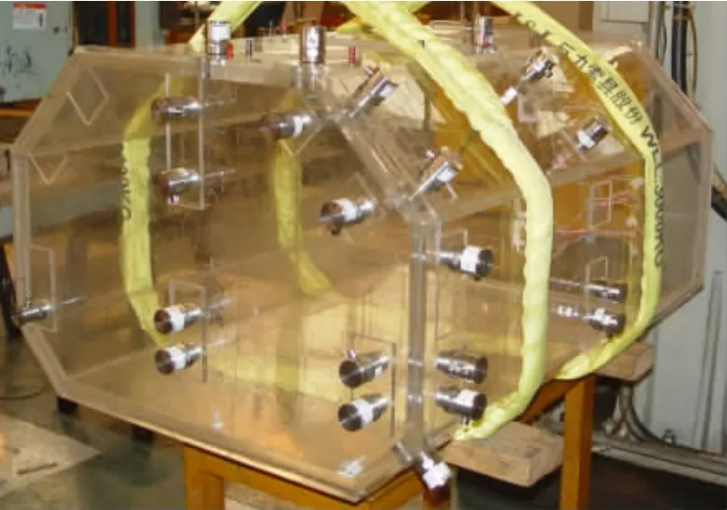
Fig.2 The model tank for sloshing test
LNG containment systems are made of materials that are more flexible than hull,such as plywood and polyurethane foam(PUF).As a result,dynamic effect needs to be considered when evaluating the severity of sloshing load.In this experiment hydro-elastic effects were modeled by placing four measurement elastic panels in the back wall containing eight strain gauges.
The experiment was done at the facility in Shanghai Jiao Tong University.The sloshing test facility has the ability to perform 3-degree of freedom motion and is consisted of a machinery,motion control unit,and related software.The motion control unit employs algorithm to control the servo motor.The maximum capacity of 1.5 tons can be tested with this facility.Experimental data and the corresponding sloshing behavior in real time were recorded for different tank motions at different filling levels,excitation amplitudes and frequencies.For each test run,the tank was always started from an upright position with predetermined frequency and excitation amplitude and each test was lasted for 5 minutes.To capture the impact load with short duration,the sampling rate was 2kHz.
3 Measurements
Serial numbers of pressure sensors are shown in Fig.3.Sensor locations vary near the still free surface depending on four filling levels(10%L,30%H,70%H and 90%H).P01-P04 in the midline of front wall are for stimulated pitch motions.P05-P08 and P13-P18 at the corners of front wall and side walls are for stimulated coupled motions.P09-P12 in the midline of side walls are for stimulated roll motions.P19-P21 in the top wall are for high filling levels.Since deflection of tank wall may cause disturbance to impact pressure,every measuring point has a bracing sheet to strengthen structure.
Five tantalum wires are disposed in the tank to monitor wave motions during sloshing tests.They are shown as tinged lines in Fig.3.
The hydro-elastic effect in structural response of the containment system in tanks of LNG carriers has also been studied.According to the insulation layer of structure,plywood box was equivalent to a 1.1m×1.1m simply supported panel,and then scaled to a 20mm×20mm sheet with thickness of 0.3mm,which was attached to the prefab orifices in the back wall.A bidirectional strain gauge was disposed in the center of each phosphor bronze sheet to measure dynamic stress(see Figs.4-7).
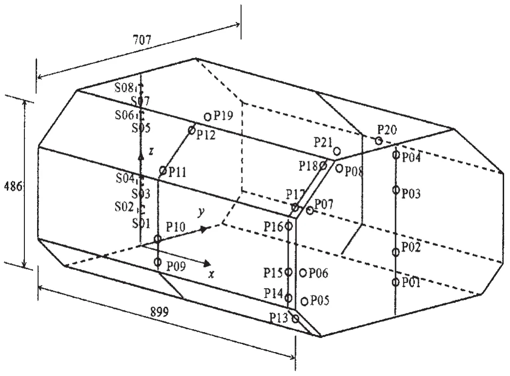
Fig.3 Sketch of model tank and positions of sensors
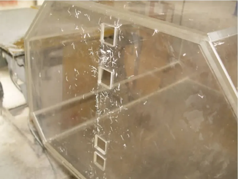
Fig.4 Model tank with hatches in the back wall
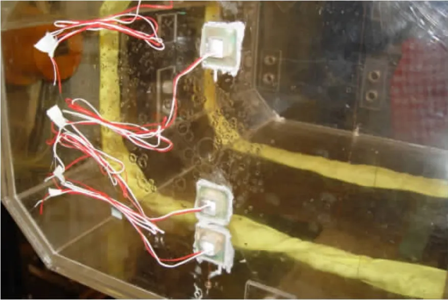
Fig.5 Strain gage in the panel
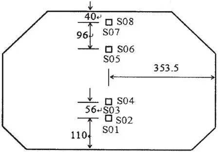
Fig.6 Location of panel in the back wall
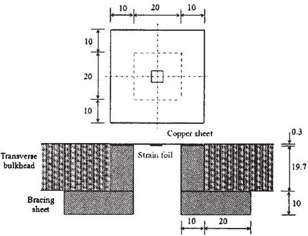
Fig.7 Rig of strain gage
4 Results and discussion
The theoretical resonance frequency for a rectangular tank can be calculated using a well known formula derived from the linear potential theory:

where,d is liquid height in the tank,l is tank length in the motion direction.
A frequency scanning method is firstly performed to obtain longitudinal resonance frequencies.This method is based on the assumption that the resonance state is associated with the maximum kinetic energy level in the tank.A certain excitation amplitude of regular(harmonic)pitch motion is considered at each filling level(10%L,30%H,70%H and 90%H).Then with determinate resonance frequencies tests are conducted at varying excitation amplitudes of pitch motions.
Transverse resonance frequencies are obtained in the same way.Model tank run subjected to stimulated roll motions with varying amplitudes and resonance frequency at each filling level.Furthermore,combined pitch and roll motion tests are carried out to investigate the fluid motions and impact pressures due to sloshing.The total number of test cases was up to eighty.
4.1 Impact loads on the model tank
4.1.1 Case 1
This is the case when single harmonic pitch motion with 30%filling depth was tested.The test was done at 0.65Hz.Fig.8 shows time history of relative wave height at w4 and w2,w4 representing the tantalum wire in the midline of front wall(close to pressure points P1,P2,P3,P4)and w2 representing the tantalum wire round the combination of front wall and side walls(close to pressure points P5,P6,P7,P8).Figs.9-11 show time history of pressure at points in the front wall,which is magnified in the time domain in right figures.
We can see from these figures:
(1)It is obvious liquid impact occurs at points(P1-P3,P5-P7)near the still water level or at the abrupt intersections of the tank walls in regular pitch motion.The variation of these pressures is neither harmonic nor periodic because of strong nonlinearity,even though the external excitation is harmonic.
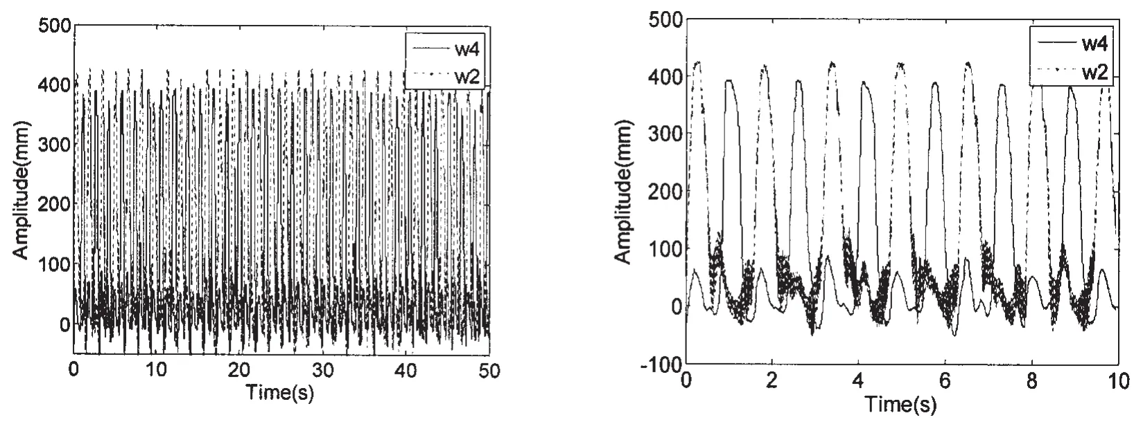
Fig.8 Time history of wave height at w4 and w2(pitch30%H,f=0.65Hz)
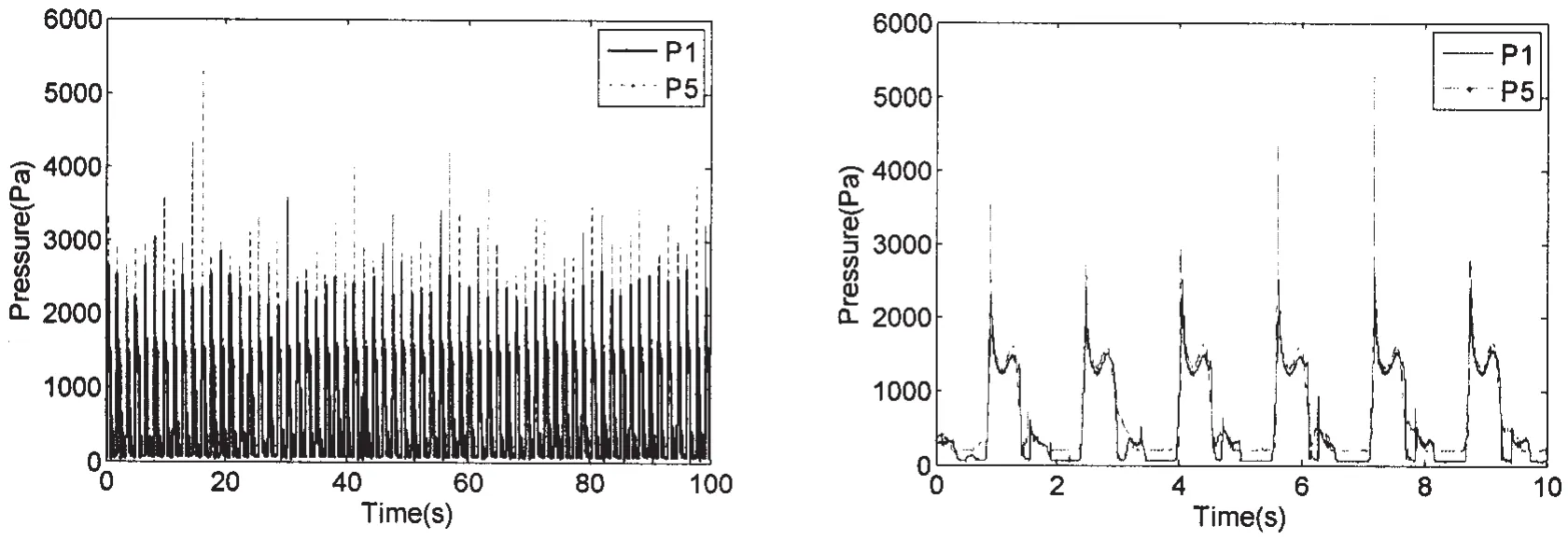
Fig.9 Time history of pressure at P1 and P5(pitch30%H,f=0.65Hz)
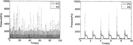
Fig.10 Time history of pressure at P2 and P6(pitch30%H,f=0.65Hz)

Fig.11 Time history of pressure at P3 and P7(pitch30%H,f=0.65Hz)
(2)There are two spikes of pressure signal in each motion period.The first,being the highest with pulse characteristics is induced by wave hitting the measuring point instantaneously.The curve then drops down to a local minimum closer to the static pressure value fleetly.The second is smaller with undulate characteristics induced by the liquid climbing up along the wall.
(3)In the 30%H pitch motion,pressure of P6,a little above the still water level,is the greatest,up to 4 000Pa,whereas pressure of P5 below the still water level and P7 are 2 800Pa and 230Pa,respectively.So in the 30%H filling level and pitch motion,liquid impact is more likely to occur at the location of P6 and amplitude of the pressure is large.
(4)Average pressure of P1 in the midline of the front wall is about a half of that of P5 at the combination of front wall and sidewall,so it does with P2 and P3.Pressure of P3 at higher location is similar to that of P7.It is observed that water surface at the combination rises more rapidly than that near the midline of the front wall due to accumulation of liquid round the lower chamfer of sidewall.It is also shown in Fig.8 that a fall of wave height at w2 is greater than that at w4.Since amplitude of impact pressure is in direct proportion to relative velocity of liquid,pressure at the corner is larger than that in the midline of front wall.
4.1.2 Case 2
This is the case when single harmonic roll motion with 30%filling depth was tested.Fig.12 shows relationship between frequency and average magnitude of peak pressure at points P10 and P15 in the midline of sidewall.Fig.13 shows relationship between frequency and wave height at w3 and w2,w3 representing the tantalum wire in the midline of side wall(close to pressure points P9,P10,P11,P12)and w2 representing the tantalum wire round the combination of front wall and side walls(close to pressure points P5,P6,P7,P8).Fig.14 shows pressure time history of P10 at various excitation amplitudes.Fig.15 shows wave height time history of w3 at various excitation amplitudes.Fig.16 shows pressure patterns at points P9-P11 along the sidewalls in identical motion period time.
We can see from these figures:amplitude of pressure varies with excitation frequency.The coupling between liquid sloshing and tank motion occurs and pressure rises up to a maximum at first mode frequency estimated by theoretical formula(1).Large fall of liquid surface and severe fluid motion including jet flow,wave breaking,spray,are observed.Fluid slaps on the tank wall loudly.
(1)In the roll motion case of low filling level,whether excitation frequency inside or outside resonance range,average pressure of P10 is always larger than that of P15 in the same horizontal altitude.Accordingly,wave heights in those two locations vary in homologous trend.
(2)In the 30%H roll motion,representative pressure increases with excitation roll angle of the tank.Wave heights keep synchronous pace with pressure.The impact has skewness higher than 1.From bottom to up(P9-P11)rise time and duration of impact get reduced and amplitude increases rapidly.
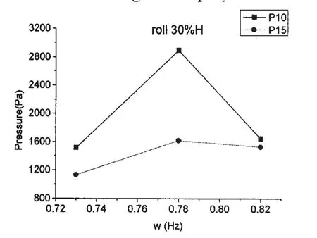
Fig.12 Relationship between frequency and pressure at P10 and P15(roll 30%H)
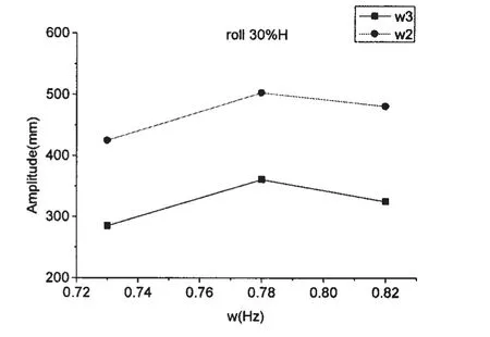
Fig.13 Relationship between frequency and wave height at w3 and w2(roll 30%H)
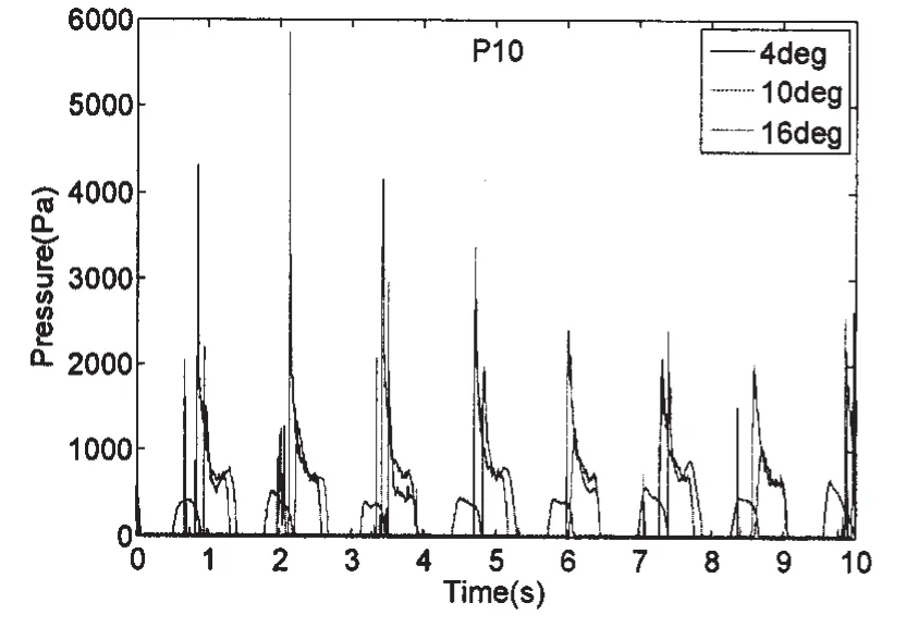
Fig.14 Comparison of pressure time history at P08(roll 30%H)
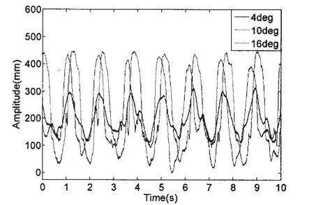
Fig.15 Comparison of wave height time history at w3(roll 30%H)
4.2 Structural response of model tank
In the test,signal of dynamic response is clear from the panel which is used to simulate containment system.Since strain characteristics are similar,just representative case is chosen for analysis.Fig.17 presents strain time history of S8 in excitation amplitude of 5 degrees 90%H pitch motion.Fig.18 presents pressure time history of P4 in correspondence to S8 in the same case.Fig.19 presents strain time history of S8 at varying amplitudes and corresponding single impulse magnified in the time domain when excitation frequency close to the natural frequency of liquid motion.We can see from these figures:
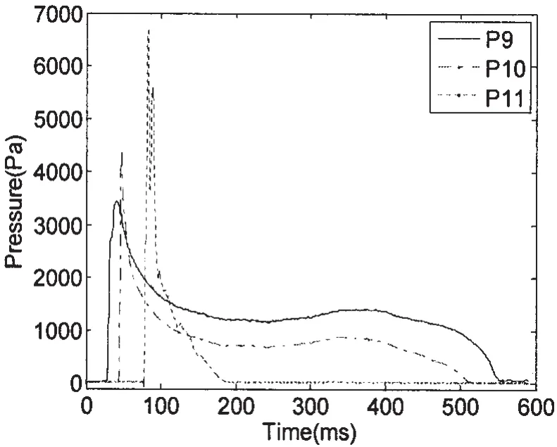
Fig.16 Comparison of pressure patterns at points along the sidewalls(roll 30%H)
(1)In high filling level,impact pressure of P4 was large,impulsive spike in the strain temporal curve of S8 occurred at impact instant.Amplitude of spike is distinctly larger than that at non-impact instant.Consequently impact load is a decisive factor in structure design of containment system and structural response can not be ignored.During the test fierce slaps on the top portion of front and back walls are observed in correspondence with measuring result.
(2)When impulsive pressure occurred,peak of structural strain signal varied irregularly as that of pressure signal even in harmonic excitation.At non-impulsive instant structural strain varied regularly resulting from wave pressures and structural inertial resistance.
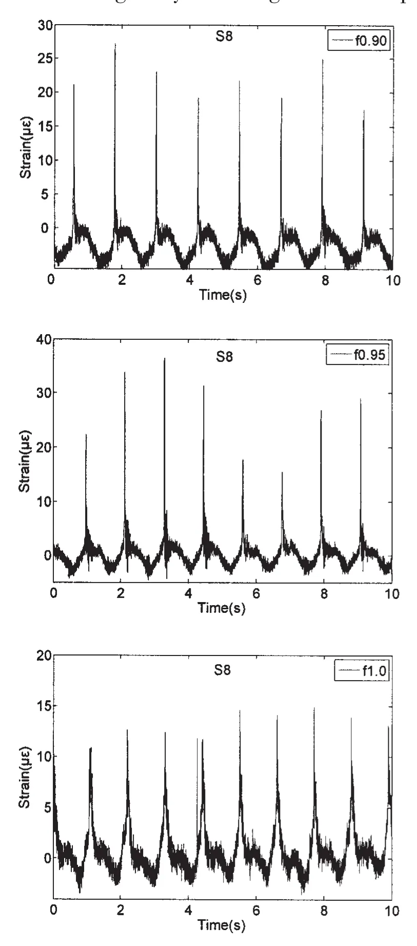
Fig.17 Comparison of strain time history of S8 when f=0.90(top),0.95(middle),1.0(bottom)(pitch 90%H)
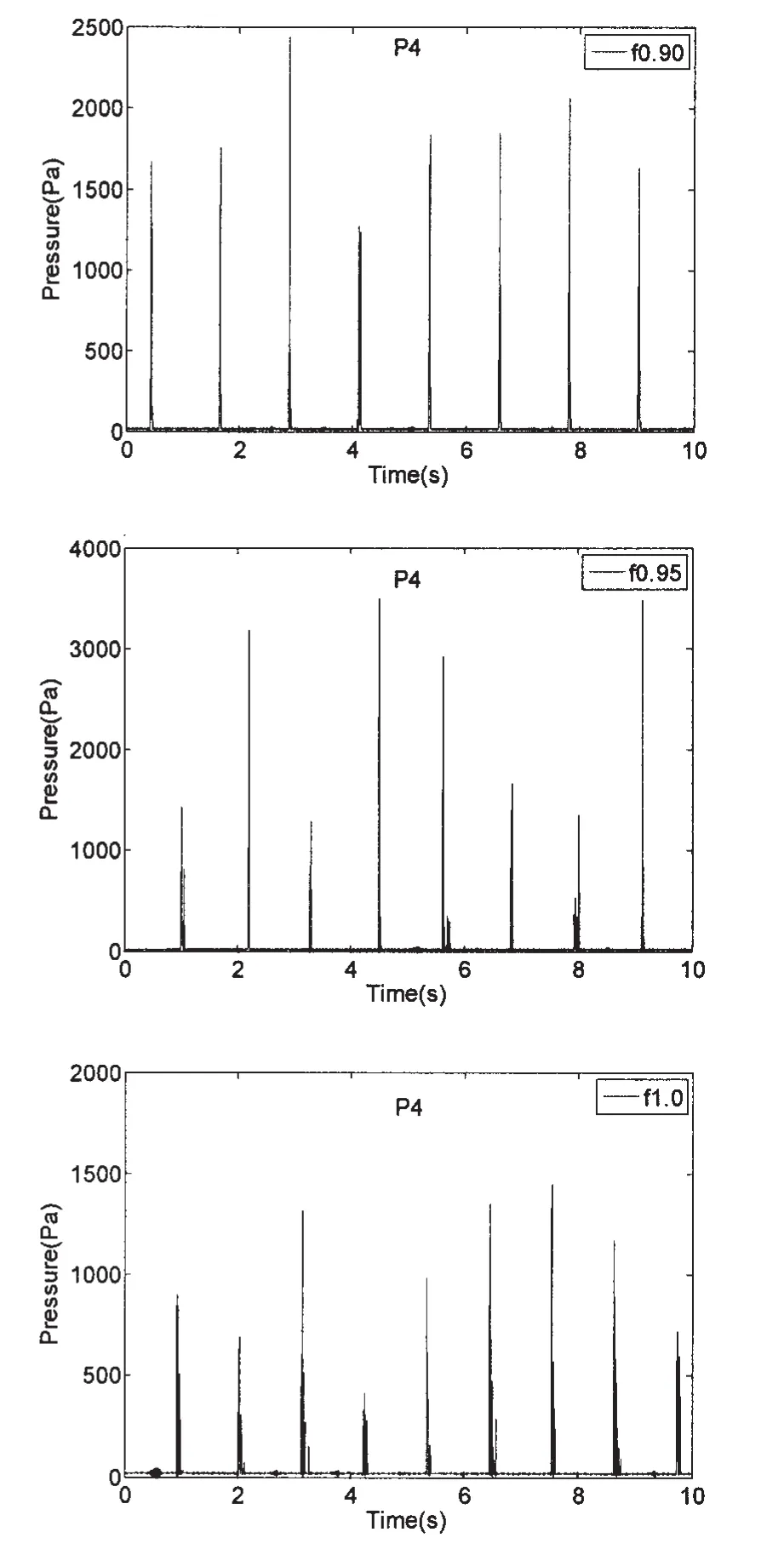
Fig.18 Comparison of pressure time history of P4 when f=0.90(top),0.95(middle),1.0(bottom)(pitch 90%H)
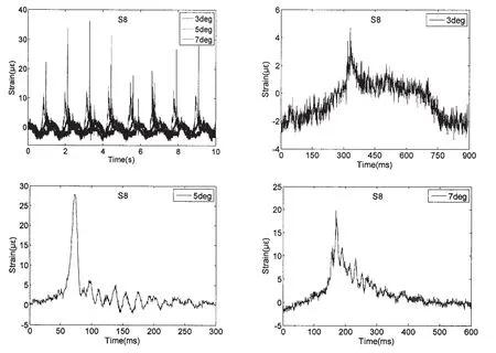
Fig.19 Comparison of strain time history of S8 at varying amplitudes(pitch 90%H,f=0.95)
(3)At the pitch excitation frequency of 0.95Hz(closest to the natural frequency of the fluid)average strain value of S8 reached the top and is larger than that at non-resonant frequency,which is the same trend of pressure with frequency.At varying excitation amplitudes of pitch motion,the variation trend of S8 strain along with excitation amplitude is similar with that of P4 pressure.
(4)In pitch motion with varying amplitudes,shapes of strain signal are irregular,as can be seen in Fig.19.In excitation amplitude of 5 degrees strain impulse has the shortest rise time and duration compared with the other two cases and are symmetric triangular.Owing to part of entrapped air escaping during the impact strain impulses are followed by oscillatory tail.
5 Conclusions
This study presents the experimental investigation on sloshing phenomenon in the tank of LNGC through model tests.Different types of fluid motion under various excitations occurred.Various characteristics of impact pressures and structural responses during liquid slapping against wall were captured and recorded.Some conclusions are drawn from analysis of test data.
(1)Due to the nonlinearity of impact pressures,magnitude of maximum peak is discrete even in regular excitation motion.
(2)In pitch motion,the impact pressures of sensors near the corner on the front tank wall are larger than those of middle transducers.This is because the water near the corner is squeezed.
(3)In roll motion,the impact pressures act on the middle of tank sidewall are larger than those near the corner.
(4)Impulsive spike was present in the temporal curve of structural strain due to sloshing impact pressure,which is distinctively different from dynamic response of local hull structure under impact.Therefore,impulsive characteristic of pressure and dynamic structural response should be considered in structure design of tank containment system.
[1]Faltinsen O M.A numerical nonlinear method of sloshing in tanks with 2D flow[J].Journal of Ship Research,1978,22:193-202.
[2]Zhu Renqing,Wang Zhidong,Fang Zhiyong.Prediction of pressure induced by large amplitude sloshing in a tank[J].Journal of Ship Mechanics,2004,8(6):71-78.
[3]Zhu Renqing,Fang Zhiyong,Wu Yousheng.Numerical simulation of viscous liquid sloshing coupled with elastic structures[J].Journal of Ship Mechanics,2006,10(3):61-70.
[4]Kyoung J H,Kim J W,Bai K J.Comparative study on the wave impact load in sloshing tank[C]//Proceedings of 23th International Conference on Offshore Mechanics and Arctic Engineering.Vancouver,British Columbia,Canada,2004.
[5]Kyoung J H,Sa Y,Kim J W,Bai K J.Finite-element computation of wave impact load due to a violent sloshing[J].Ocean Engineering,2005,32:2020-2039.
[6]Wemmenhove R,Luppes R,Veldman A P E,Bunnik T.Numerical simulation of sloshing in LNG tanks with a compressible two-phase model[C]//Proceedings of 26th International Conference on Offshore Mechanics and Arctic Engineering.San Diego,USA,2007.
[7]Wemmenhove R,Luppes R,Veldman A E P,Bunnik T.Application of a VOF method to model compressible two-phase flow in sloshing tanks[C]//Proceedings of 27th International Conference on Offshore Mechanics and Arctic Engineering,Estoril,Portugal,2008.
[8]Gavory T.Innovative tools open up new prospects for liquid motion model tests[C]//Proceedings of GASTECH Conference.Spain,2005.
[9]Zhao R,Rognebakke O,Zheng X.Wave and impact loads in design of large and conventional LNG ships[C].Proceedings of RINA Conference on Design and Operation of Gas Carriers,2004:75-85.
[10]Lee H,Kim J W,Hwang C.Dynamic strength analysis for membrane type LNG containment system due to sloshing impact load[C].Proceedings of RINA Conference on Design&Operation of Gas Carriers,2004:39-47.
[11]Tim Bunnik,Rene Huijsmans.Large scale LNG sloshing model tests[C].Proceedings of the Sixteenth International Offshore and Polar Engineering Conference.Lisbon,Portugal,2007.
大型LNG船液舱晃荡载荷及响应模型试验研究
徐国徽,祁恩荣,徐 春,顾学康
(中国船舶科学研究中心,江苏 无锡 214082)
液舱晃荡是大型液化天然气船液舱设计中的重要问题之一,具有强非线性和离散性,很难确定其载荷值。为了研究大型液化天然气船液舱晃荡冲击载荷及其对结构的响应,文章开展了典型菱形液舱的三维晃荡模型试验,获得了大型LNG船液舱在各种运动模式下的流体拍击舱壁的冲击载荷特性以及液舱围护系统结构在晃荡冲击载荷作用下的动响应特征。
大型LNG船;晃荡载荷;模型试验;冲击压力;结构动响应
U661.4
A
徐国徽(1985-),女,中国船舶科学研究中心工程师;
顾学康(1963-),男,中国船舶科学研究中心研究员。
U661.4
A
1007-7294(2011)12-1374-10
date:2011-08-09
祁恩荣(1964-),男,中国船舶科学研究中心研究员;
徐 春(1980-),男,中国船舶科学研究中心工程师;
- 船舶力学的其它文章
- On Generation of Standardized Load-time Histories and Standardized Load Spectra
- Study of the Prediction of the Engine’s Underwater Exhaust Noise
- Coupled Vibration of Fluid-filled Functionally Graded Material Cylindrical Shell
- Nonlinear Model for Vibration Analysis of Fluid-conveying Pipes via the Incremental Harmonic Balance Method
- Study of Damage Characteristics during Fatigue by Acoustic Emission Techniques
- Comparative Analysis of Vortex Induced Nonlinear Vibration of Casing Pipe under Three Different Boundary Conditions

