Nonlinear Model for Vibration Analysis of Fluid-conveying Pipes via the Incremental Harmonic Balance Method
MENG Dan,CHEN Liang
(1 School of Civil Engineering,Qingdao Technological University,Qingdao 266033,China;2 School of Architectural,Qingdao Technological University,Qingdao 266033,China;3 Architectural Design and Research Institute,Qingdao Technological University,Qingdao 266033,China)
Nonlinear Model for Vibration Analysis of Fluid-conveying Pipes via the Incremental Harmonic Balance Method
MENG Dan1,CHEN Liang2,3
(1 School of Civil Engineering,Qingdao Technological University,Qingdao 266033,China;2 School of Architectural,Qingdao Technological University,Qingdao 266033,China;3 Architectural Design and Research Institute,Qingdao Technological University,Qingdao 266033,China)
A new nonlinear model of a fluid-conveying pipe is presented.Considering the effect of the internal fluid and excitation,the nonlinear differential equations are derived based on Kane’s equation in combination with a Ritz method by using non-linear Lagrange strain theory.The equations of motion are linearized in the neighborhood of the equilibrium position to carry on the multimode linear stability analysis.In addition,the time histories for the displacements are obtained by using the Incremental Harmonic Balance(IHB)method.The validity of the new model is substantiated by comparing the model and results with those proposed by Païdoussis(1998).
nonlinear model;Kane’s method;vibration analysis;Incremental Harmonic Balance(IHB)method
Biography:MENG Dan(1980-),male,Ph.D.,lecturer of Qingdao Techndogical University,E-mail:md1101@163.com.
1 Introduction
Vibrational dynamics of pipes conveying fluid has been the subject of numerous scientific investigations due to their wide applications.During the period from 1970 to 2000,based on the linear equations of motion for pipes supported at both ends proposed by Feodos’ev and Housner in 1950s,the literature on this topic literally exploded,with linear and nonlinear,twoand three-dimensional,theoretical and experimental studies,not only for the plain pipe and pipes with added spring supports,masses and dashpots,somewhere along the length of the pipe,but also for pipes supported at both ends.This was the result of gradual realization that this problem is a new paradigm in dynamics,displaying in a simple system a wide variety of the dynamical features of more complex engineering problems.Moreover,the fluid-conveying pipe system has the advantage that one can fairly easily conduct experiments to verify the theory.A thorough literature review will not be undertaken in this paper.For that,the reader is referred to Ref.[1-4].Most of the previous nonlinear equations were derived from the infinitesimal strain theory either by Newton approach[4]or by Hamilton’s principle[5].
In the study of nonlinear systems,it is often of interest to find the time response for specific initial conditions.In the case of systems that can be represented as first order systems,excellent codes are nowadays available from netlib,such as LSODE written by Hindmarch[6]or those by Hairer et al[7].They enable the understanding of the dynamics of nonlinear systems and the classification of the types of response.The analyst,however,does not have that much of a choice when implicit second order ordinary differential equations are to be solved.The most popular method that can be used for finding periodic solutions of implicit second order ordinary differential equations is known as the Harmonic Balance(HB)method in the vibration literature[8],and as the Describing Function(DF)approach in the control and aeroelasticity literature[9].It is computationally very efficient for obtaining steady state solutions of nonlinear dynamics problems,but it is usually too restrictive,mainly because:the solution is assumed to have one dominant frequency component-or at most two-and the non-linearity has to be small;and one needs to know a great deal about the solution a priori or to carry enough terms in the solution and check the order of the coefficients of all the neglected harmonics,since otherwise one might obtain an inaccurate approximation,as shown by Nayfeh and Mook[8].
Since the fluid-conveying pipes is the system which have beam-like shapes and undergo excitation,in this paper we will start from a new angle of view to address this problem.In order to drive equations of motion including the influence of internal fluid and excitation,the Kane’s method is adopted,and the effect of nonlinearity is taken into account with the help of the general Lagrange strain theory instead of the conventional infinitesimal strain theory.Utilizing the Rayleigh-Ritz method,the discretized equation of motion is obtained.This is an alternative approach to the existing methods utilizing Newtonian balance equations or Hamilton’s principle is thus provided.Then the equations of motion are linearized in the neighborhood of the equilibrium position,and solved by the complex damping method for multimode linear stability analysis.The results are compared with existing works[1].Furthermore,the resulting equations with continuous cubic nonlinearities are solved using the Incremental Harmonic Balance(IHB)method[10],the histories of the displacement are computed,and the results are also compared with existing works.
2 Equations of motion
A simply-supported slender shape pipe conveying fluid attached to a rigid base A and the configurations before and after deformation are exhibited by Fig.1.The in-plane deformation u→of the pipe can be represented by two scalar variables in 2-D space.Conventionally,Cartesian variables u1and u2,as shown in the figure,are widely utilized.In the present modelling method,a non-Cartesian variable along with one Cartesian variable is used instead of two Cartesian variables:s denotes the arc length stretch,rather than u1,and measures the Cartesian distance of a generic point in the axial direction of the undeformed configuration.O is a reference point identifying a point fixed in a floating frame in the system,while r→is a po-sition vector from O to the location of P in the undeformed body.
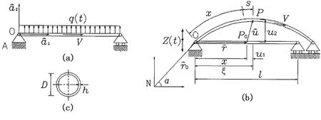
Fig.1 Schematics of a simply-supported straight pipe conveying fluid:(a)model of pipe before deformation;(b)the pipe after deformation and kinematics subject to excitation;(c)the cross-section of the pipe
In this study,Kane’s method is employed to derive the equations of motion.This method provides a direct and systematic way of deriving ordinary differential equations of motion for continua such as beams,plates and shells.With the assumptions given above,the equations of motion for pipes can be obtained as follows[11]:

here,the expression of generalized inertia forceand generalized force Fiare


in which ρ and ρfare the mass per unit length of the pipe and internal fluid,respectively,are the time derivatives of the generalized co-ordinates.,andare the inertia velocity and accelerations of the center point P of a differential element of the pipe and internal fluid,respectively.
For the present modelling method,the following strain energy expression is used,in which Tais the apparent tension and M2is the bending moment[11-14].

In the pipe’s wide applications,some of them will be employed in the water.In this case the pipe oscillates transversely to a stationary and uniform flow of free stream velocity,in which the inertia force and the lift forces are exerted on the system as the external force.The expression for the inertia force and the lift forces are exerted on the system H used in this section,reads[15]

in which FL= ρeU2DCL/2 is the lift force for VIV,ρ′=CaρeπD2/4 is the added mass per unit length of the pipe,C′=δωsρeD2is the equivalent fluid damping.In which Cais added mass coefficient,taken as 1.0;ρeis the density of sea water,D is the outer diameter of the pipe,δ is the viscous force coefficient,taken as 0.8;ωs=2πStU/D is the Strouhal frequency,Stis the Strouhal number,taken as 0.2;U is velocity of currents and waves,CLis the vortex lift coefficient.
Suppose that the vertical excitation which the motion of the pipe subjected to is dictated by a excitation function as

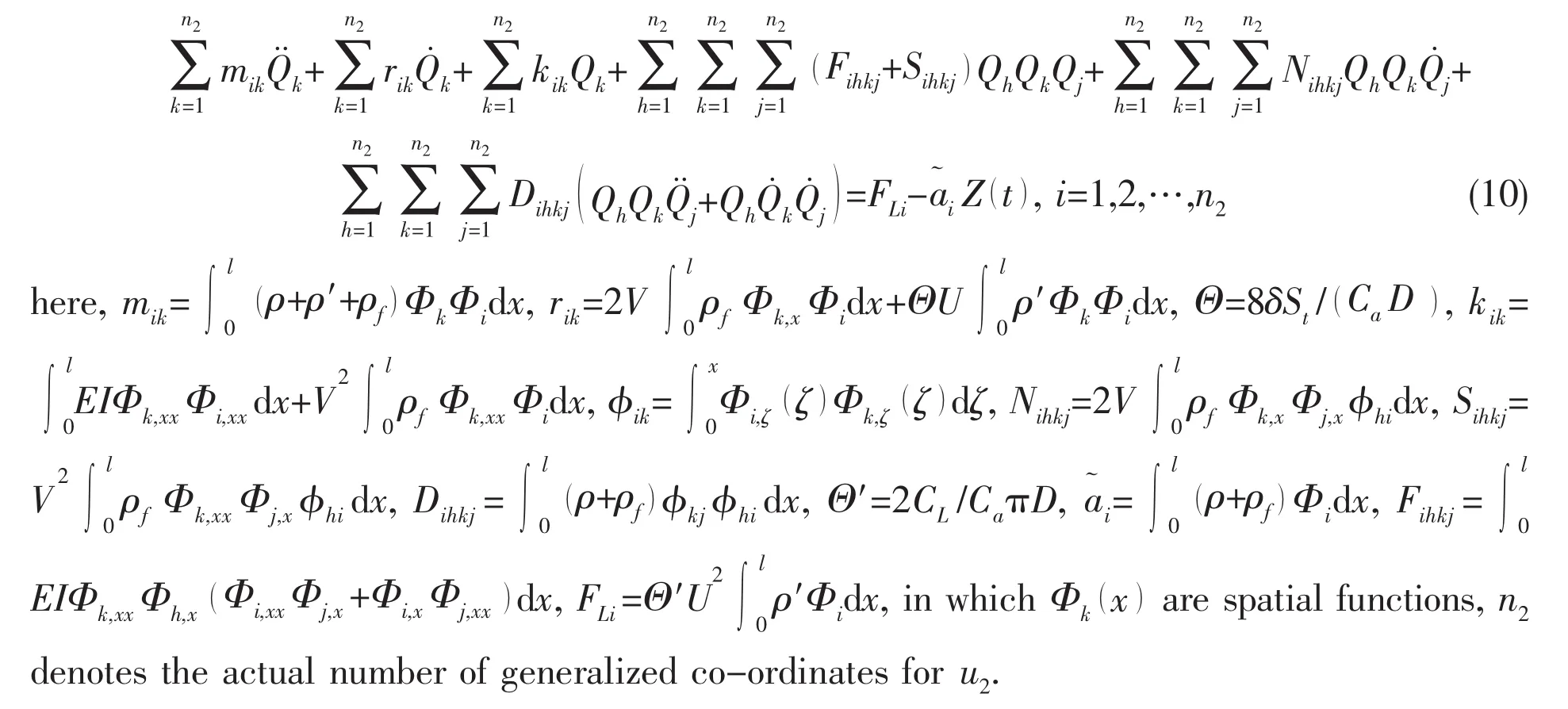
in which Z0and ϖ are the acceleration amplitude and angular frequency of the harmonic vibration,respectively.Thus,substituting Eqs.(3)-(9)into Eq.(1)we can get the nonlinear equations of transverse vibration for the pipe conveying fluid[16]
It is interesting to compare and contrast these equations with those previously published.The equations proposed in this paper are compared with those gained by Païdoussis and his co-workers[1,17].Using the same notations of this paper,the equations of Païdoussis and his coworkers can be rewritten as


The nonlinear terms of this model will not be detailed out here,the specific content of nonlinear terms can be found in the literature of Païdoussis and his co-workers easily.Neglect the external fluid and excitation,the main difference of Eq.(10)from Eq.(11)is shown in nonlinear terms,Fihkj,Sihkj,Nihkjand Dihkj,which have different form.But the linear terms are the same in both equations of motion.
3 Multimode linear stability analyses
The external force and the vertical excitation are not considered,introducing the dimensionless quantities

the equation of motion can be expressed in the following dimensionless form


The discretized equations of motion can be verified by computing the natural frequencies of the pipe.To this end,it is necessary to obtain the linearized equations of motion in the neighborhood of the equilibrium position.When the excitation and the external force are neglected,the linearized equation of Eq.(13)is rendered by

In order to find the natural frequencies from Eq.(14),it is convenient to transform Eq.(14)into

Assuming the solution of Eq.(16)as Y(t)=Y,the complex eigenvalues λndepend on the internal fluid velocity because of the matrix[C]and[K].The critical speeds of the internal fluid are the values of V at which the imaginary part of any of the minimum eigenvalues to be zero.The real part of the eigenvalues is related to the amount of damping exhibited by a given eigenvalue.
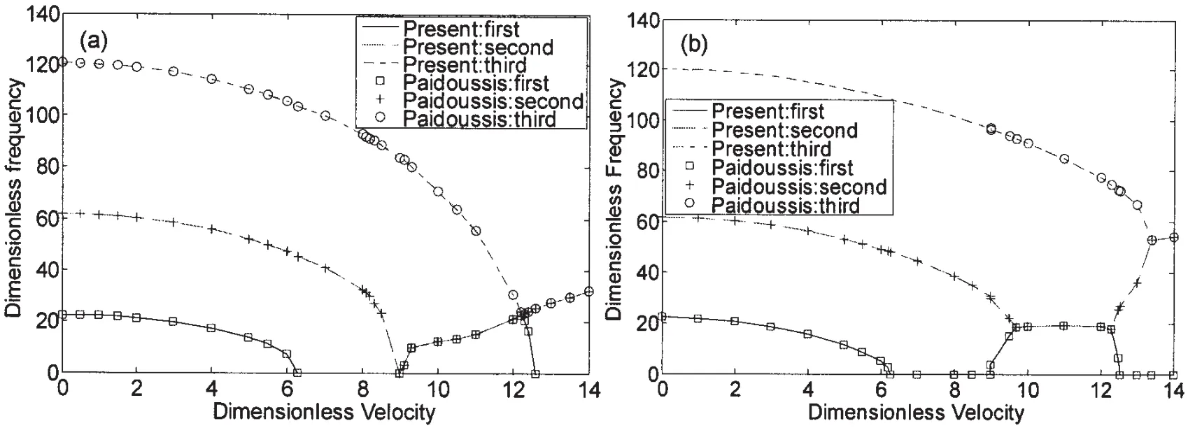
Fig.2 Comparison of results of Païdoussis and the present formulation for:(a)ζ=0.1;(b)ζ=0.8
Païdoussis probed into the static and dynamic instabilities of pipes conveying fluids[1].Therefore,the results for the present model will be validated with those of Païdoussis under two different values of non-dimensional parameter ζ(ζ=0.1 and ζ=0.8)with the clampedclamped boundary condition.The numerical results are shown in Fig.2,which exhibits the relationship between the dimensionless flow velocity and the dimensionless frequencyWhereis the frequency of the structure in rad/s,whileVl.For ζ=0.1,the divergence occurs first when the flow velocity reaches 6.28,and if the flow velocity is increased further,the second mode divergence occurs at flow velocity of 8.99.Upon further increasing the flow velocity,the first and second mode frequencies increase together and join with the third mode.The first mode then decreases to zero and the second and third modes move together to the fourth one.In the case of ζ=0.8,there is a stabilized region between u=8.99 and 9.6.From both figures,it is clear that the present formulation provides excellent agreement with those of Païdoussis[1].It must be pointed out that not only do the curves match well but also the various physical phenomena that occur in those results have been correctly predicted by the current formulation.
4 Incremental Harmonic Balance(IHB)method
The purpose of this section is to describe the method that can be used for finding periodic solutions of nonlinear oscillators of the type of Eq.(13).Contrary to small parameter techniques that require the nonlinear terms to be small,it is preferable to have a scheme that is applicable in a more general case.Urabe[18]was one of the first to introduce a multi-harmonic balancing procedure.He combined it with the Newton-Raphson iteration technique to treat strong nonlinearities and he referred to this as a Galerkin approximation with a characteristic function containing trigonometric functions.Similarly,the Incremental Harmonic Balance(IHB)method was developed by Lau et al[19]to take into account multiple harmonic components due to the nonlinear forces.Hence,in the usual terminology,the IHB can be referred to as a combined Incremental Ritz-Galerkin Harmonic Balance method or as a Harmonic Balance Newton-Raphson(HBNR)method.Indeed,Ferri[20]showed that the IHB and the HBNR methods are equivalent.The IHB method was successfully applied to various types of nonlinear structural systems,ranging from systems with continuous cubic nonlinearities to dry friction damper problems where the nonlinear force is discontinuous[21].From the assumption that the value of n2for 5,with βihkj=βihjkand γihkj=γihjkin mind,Eq.(13)can be rewritten as

And now all derivatives are now with respect to τ.The first step in applying the IHB method is similar to a Newton-Raphson procedure:Starting from an initial guess of the solution of Eq.(18)is(yk0,ϖ0,fi0),a neighbouring solution is reach through an incrementation(Δyk,Δϖ,Δfi)using a Taylor series expansion.Neglecting the non-linear terms in Δyk,Δϖ and Δfi,a linearized incrementation equation is obtained:

The second step in the IHB method is the process of harmonic balance.Starting from known or estimated coefficients akmand bkm,the assumed or sought periodic solution is written as


By using the sought periodic solution,it is straightforward to obtain

By differentiation of Eq.(22),one obtainsandas well.Substituting Eq.(22)and,into Eq.(19)and make use of the harmonic balance method in one period yields

It can be seen that the number of unknowns exceeds the number of equations by two,Δϖ and Δfi.Hence,one needs to add a constraint.Recalling that the solution sought is for a given acceleration amplitude or of a predefined frequency,the constraint is either Δfi=0 or Δϖ=0.If Δfi=0,fiis said to be the active increment and the solution for a different fiis obtained by incrementing fifrom point to point.Similarly,if Δϖ=0,ϖ is the active increment.Once the incremental coefficient ΔAkis found,the assumed solution can be updated and the process is repeated until a convergence criterion is met.This criterion may be defined as the infinite norm of the incremental vecter having to be smaller than a certain value.
5 Results and discussion
The dynamic responses with transverse displacement being our primary concern are computed with same parameters and material properties except that the internal fluid velocity is prescribed as,V=0ms-1and V=131.3ms-1.And the comparisons of dynamic responses are made between this new model and Païdoussis’ model[1,4].Both of them use the same basis functions with the clamped-clamped boundary condition.In order to make up the vortex lift,the external transverse load q herein is dictated by a harmonic excitation with frequency and constant amplitude being ϖfand P0,respectively,namely,q ()t=P0sinϖft.The transverse displacements at x=L/2 of the nonlinear models are plotted in Figs.3 and 4.Figures show that,in this case,although the new model and Païdoussis’ model have different nonlinear terms,as seen in Eqs.(10)and(11),there is no difference between the dynamic responses obtained from these two models.
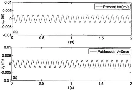
Fig.3 Dynamic responses of the transverse displacement for the non-linear model when the internal fluid velocity is V=0m/s:(a)the present model;(b)Païdoussis’ model
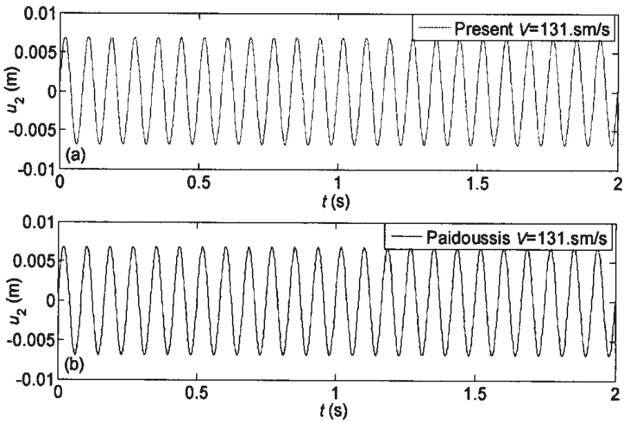
Fig.4 Dynamic responses of the transverse displacement for the non-linear model when the internal fluid velocity is V=131.3m/s:(a)the present model;(b)Païdoussis’ model
From the Morrison wave theory,the hydrodynamic drag forces are involves two key factors:drag force and inertial mass coefficients.The drag force coefficients describe the pipes’surface roughness,which are affected by Reynolds Number.Over a time,converging onto a steady state as depicted in Fig.11.In this study,only the steady flow is taken into consideration,without considering the impact of lift force,the dynamic reaction of the surrounding water on the pipe is simplified as the equivalent fluid damping,according to Blevins[15],which is adopted as the damping force on the pipe.In the present model,the equivalent fluid damping is embodied in the second term of the equation.The dynamic responses of the transverse displacement as a function of the damping force caused by external fluid velocity are discussed and the results are presented in Fig.5.In this case,the black line represents the vibration state of the pipe without the impact of the fluid damping,which corresponds to the result of Païdoussis’ model.But we can see from the figure,the drag forces play a significant role in reducing the maximum amplitudes of dynamic responses,as the external fluid velocity increases,as expected,the amplitude of vibration decreases accordingly.The cause lies in the fluid damping term,which changes with the external fluid velocity.
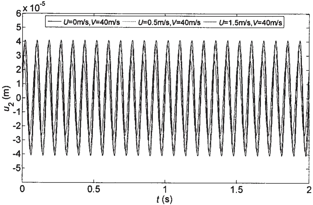
Fig.5 Dynamic responses of the transverse displacement as a function of external fluid velocity
When the structure is subjected to earthquake,its dynamic characteristic will change a lot.Then the dynamic responses of the simply-supported pipe with vertical excitation prescribed by Z(t)=Z0sinϖt are discussed next.Some case studies are carried out to analyze the response characteristics.Figs.6-7 depict the histories of the displacement of the pipe under different conditions.The internal flow speeds from 0 to 230m/s are considered in the parametric studies.Losses due to internal flow frictions in the pipe system clearly deter the internal flow speed and are not considered in this investigation.The dynamic responses of the pipes transporting the internal fluids are illustrated in Fig.6.The results clearly exhibit that the displacement responses of the pipes with bending rigidity tend to converge onto steady state response amplitudes.And it demonstrates that as the internal flow speed increases,the response amplitude has decreased.
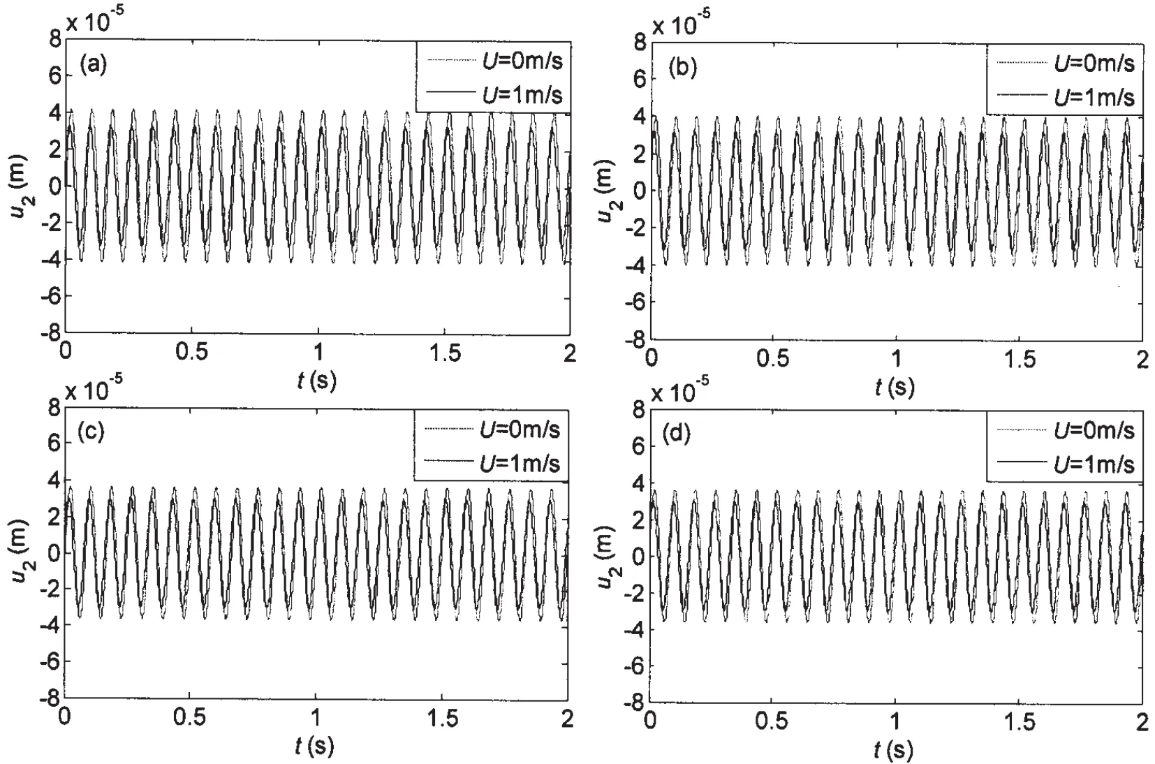
Fig.6 Dynamic responses of the transverse displacement as a function of internal fluid velocity when the excitation is given by Z0=1.0m/s2,ϖ=24πrad/s:(a)V=0m/s;(b)V=65.7m/s;(c)V=164.2m/s;(d)V=230.0m/s
Through the introduction and analysis of a simple discrete system,the important modelling issues motion-induced stiffness variations,and their contribution to non-linear equations of motion have been investigated.Fig.7 demonstrates the responses of the transverse displacement at mid-point of the pipe with respect to combined internal fluid and overall motion ex citations,which manifests that the increasing angular frequency of overall motion reduces the response magnitude,while the impact of the internal fluid velocity is not significant,as expected.If one chooses a special set of deformation variables such that the strain energy of the structure is accurately characterized in a quadratic form in these variables,then it is possible to develop differential equations of motion which are totally linear in the deformation variables and yet still exhibit proper stiffness variations.This is the approach taken in the modeling method developed in this paper,wherein the strain energy of the 3-D beam is expressed in a quadratic form by using the stretch variable of the beam.If one chooses the Cartesian set of deformation variables,the stiffness variation due to large overall motion cannot be properly predicted by a linear model.If proper motion-induced stiffness variation is to be accommodated,at least up to second degree terms in the stretch strain should be retained.

Fig.7 Dynamic responses of the transverse displacement as a function of angular frequency when the external fluid velocity is U=1m/s and Z0=1.0m/s2:(a)ϖ=2π;(b)ϖ=6π;(c)ϖ=10π;(d)ϖ=24π
6 Conclusions
In this paper,the nonlinear equations of 2-D motion of pipe conveying incompressible fluid have been derived based on the Kane’s method,they are quite similar to those obtained by Païdoussis(1998).But in their most general form the present equations account for the possible existence of:(1)a stationary and uniform external flow of free stream velocity,and(2)vertical excitation.The equations of motion are solved by the complex damping method for the natural frequency.The Incremental Harmonic Balance method was proposed to predict the existence of periodic solutions.As suggested in the literature,it is capable of solving problems defined by implicit equations.Furthermore,the numerical results from the proposed model are compared with those from Païdoussis’ model.
It is still noteworthy that the approach developed here can also be used to handle arbitrary boundary conditions.Adaptation of the model for a specific set of geometric boundary conditions requires only the selection of a suitable set of basic functions.
[1]Païdoussis M P.Fluid-structure interactions:Slender structures and axial flow[M].Academic Press,London,1998.
[2]Meng Dan,Guo Haiyan,Xu Sipeng.Nonlinear dynamic model of a fluid-conveying pipe undergoing overall motions[J].Appl.Math.Model,2011,35:781-796.
[3]Meng Dan,Guo Haiyan,Xu Sipeng.Flow-induced vibration stability analysis of fluid-conveying pipes[J].J Vib.and Shock,2010,29(6):86-89.(in Chinese)
[4]Semler C,Li G X,Païdoussis M P.The non-linear equations of motion of pipes conveying fluid[J].J Sound Vib.,1994,169:577-599.
[5]Folley C N,Bajaj A K.Spatial nonlinear dynamics near principal parametric resonance for a fluid-conveying cantilever pipe[J].J Fluid Struct.,2005,21:459-484.
[6]Hindmarsh A C.Scientific Computing,North-Holland[M].ODEPACK,a systematized collection of ODE solvers,Amsterdam,1983.
[7]Hairer E,Norsett S P,Wanner G.Solving ordinary differential equations[M].Springer-Verlag,Berlin,1993.
[8]Nayfeh A H,Mook D T.Nonlinear Oscillations[M].Wiley-Interscience,New York,1979.
[9]Gelb A,Vander Velde W E.Multiple-input describing functions and nonlinear system design[M].McGraw-Hill,New York,1968.
[10]Semler C,Gentleman W C,Païdoussis M P.Numerical solutions of second order implicit non-linear ordinary differential equations[J].J Sound Vib.,1996,2:553-574.
[11]Kane T R,Ryan R R,Banerjee A K.Dynamics of a cantilever beam attached to a moving base[J].J Guid.Control Dynam.,1987,10(2):139-151.
[12]Yoo H H,Ryan R R,Banerjee A K.Dynamics of flexible beams undergoing overall motion[J].J Sound Vib.,1995,181(2):261-278.
[13]Timoshenko S P,Gere J M.Mechanics of Materials[M].Litton Educational Publishing,New York,1972.
[14]Chucheepsakul S,Monprapussorn T,Huang T.Large strain formulation of extensible flexible marine pipes transporting fluid[J].J Fluids Struct.,2003,17:185-224.
[15]Blevins R D.Flow-induced vibrations[M].2nd edn.Van Nostrand&Co.,New York,1990.
[16]Meng Dan,Guo Haiyan,Xu Sipeng.A new nonlinear model for vibration analysis of fluid-conveying pipes undergoing overall motions[C].Proceedings of Second International Conference on Modelling and Simulation,2009,7:248-253.
[17]Wadham-Gagnon M,Païdoussis M P,Semler C.Dynamics of cantilevered pipes conveying fluid.Part 1:Nonlinear equations of three-dimensional motion[J].J Fluid Struct.,2007,23:545-567.
[18]Urabe M.Galerkins procedure for nonlinear periodic systems[J].Archive for Rational Mechanics and Analysis,1965,20:150-152.
[19]Lau S L,Cheung Y K,Wu S Y.A variable parameter incrementation method for dynamic instability of linear and nonlinear vibration of elastic systems[J].Journal of Applied Mechanics,1982,49:849-853.
[20]Ferri A A.On the equivalence of the incremental harmonic balance method and the harmonic balance Newton_Raphson method[J].J Applied Mech.,1986,53:455-457.
[21]Pierre C,Ferri A A,Dowell E H.Multi-harmonic analysis of dry friction damped systems using an incremental harmonic balance method[J].J Applied Mech.,1985,52:958-964.
基于增量谐波平衡法的输流管道非线性振动分析
孟 丹1, 陈 亮2,3
(1青岛理工大学 土木工程学院,山东 青岛266033;2青岛理工大学 建筑学院,山东 青岛266033;3青岛理工大学 建筑设计研究院,山东 青岛 266033)
考虑内、外流体的影响,利用Kane方法和拉格朗日应变理论建立了输流管道的二维非线性动力学模型。将动力学模型在平衡位置附近线性化,进行输流管道的线性稳定性分析。采用增量谐波平衡法求解包含三次非线性项动力学模型的稳态周期解。探讨了不同参数影响下输流管道的非线性动力响应以及内流流速的大小对管道动力特性的影响。
非线性模型;Kane方法;振动分析;增量谐波平衡法
O353.1
A
孟 丹(1980-),男,博士,青岛理工大学土木工程学院讲师,从事海洋工程非线性动力分析方面的研究;
陈 亮(1980-),男,硕士生。
O353.1
A
1007-7294(2011)12-1416-13
date:2011-07-07
Supported by National Natural Science Foundation of China(50808105);Shandong Province Natural Science Foundation(BS2009SF003)
- 船舶力学的其它文章
- Numerical Research on Ventilated Supercavity Shape and Flow Structure in the Turning Motion
- A Comparative Investigation on Optimization of Propeller Blade Section Design
- Experimental Investigation of Sloshing Loads and Structural Dynamic Responses in Tanks of LNG Carriers
- Comparative Analysis of Vortex Induced Nonlinear Vibration of Casing Pipe under Three Different Boundary Conditions
- Study of Damage Characteristics during Fatigue by Acoustic Emission Techniques
- Coupled Vibration of Fluid-filled Functionally Graded Material Cylindrical Shell

