机身整体壁板在轴压载荷下后屈曲计算及结构优化
孙为民1 郭 亮1 童明波1 董登科2
(1.南京航空航天大学飞行器先进设计技术国防重点学科实验室,南京,210016,中国;2.飞机强度研究所,西安,710065,中国)
INTRODUCTION
The design,the manufacture,the test,and the analysis methodologies on integrally stiffened panels are important for commercial transport aircraft.Over the last decades,to maintain the leadership and competitiveness on the global market,the aerospace industry in United States has explored the new technologies of the integrally stiffened panel[1-4]. However, until recently,there are only a few of reports on the integral airframe structures for domestic largescale civil airplane.
The post-buckling computation of the panel involves geometrical and physical nonlinearity calculation, thus it is so complex. The experiment and the semi-empirical method[5]are used to obtain the post-buckling load.However,the experiment usually takes a lot of money and time,and the semi-empirical method can yield the detailed damage mode of the panel.
Therefore,based on the structure and the axial compressive experiment of the build-up panel,the exact finite element model(FEM)of the designed integral panel is analyzed.The FEM results are discussed in details and the optimum structure of the integral panel is given to provide a basis for the design.
1 PANEL DESCRIPTION
The build-up panel test specimen has3 stringers and 2 frames.The overall dimensions of the panel are 542 mm in length,540 mm in width and 1 560.9 mm in radius,as shown in Fig.1.
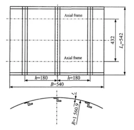
Fig.1 Overall dimensions of panel
The panel skin is made of a 1.6 mm thick 2024-T4 aluminum sheet partly milling to 1.3 mm.The stringers are mechanically fastened to the panel skin.And,an aluminum tear strip is bonded to the panel skin on the frames and the stringers.The panel frames are made of 7075-T62 aluminum Z sections and 432 mm apart.The stringers are made of7075-T62 aluminum Z sections spaced 180 mm apart.The frames are mechanically fastened to the panelskin by aluminum shear clips.The stringer and the frame details of build-up panel are show n in Fig.2.
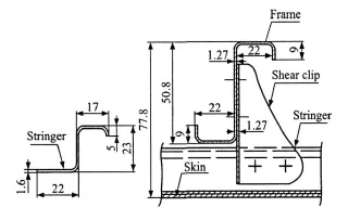
Fig.2 Stringer and frame of build-up panel
The overall dimensions of the designed integral panel are the same as the build-up panel for the equal weight requirement.The panel is machined from one 2024-T4 thick plate. The stringer and the frame details of integral panel are shown in Fig.3.The frames are mechanically fastened to the panel skin directly.
Typical material properties of the two aluminum alloys used to construct the panel are listed in Table 1,where ecyis the yielding strength of materials,andebthe limit strength.
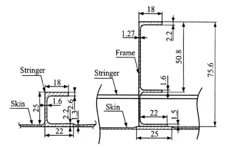
Fig.3 Stringer and frame of integral panel
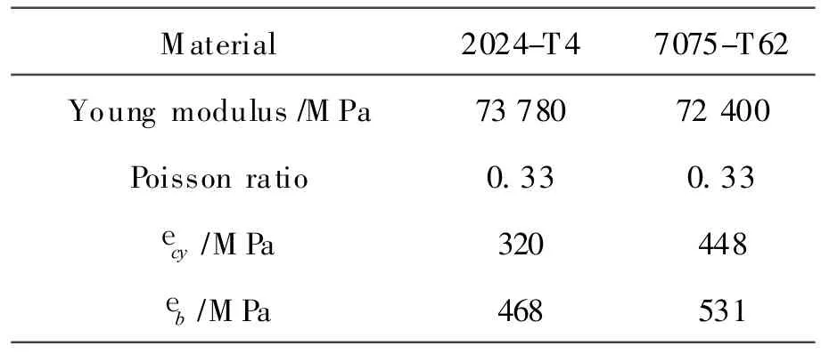
Table1 Typical material properties
2 AXIAL COMPRESSIVE LOADING EXPERIMENT
Three test specimens(1#,2#,3# )of build-up panel are made.The top-edge and the bottom-edge of panels are clamped by two steel blocks,and two side edges are clamped by the specialfixture. Itensures that appropriate boundary conditions are imposed on a curved panel to provide a stress state for representing a cylindrical shell[6].The test piece is mounted on the testmachine and subjected to an axial compression load.
In the experiment,the preload is achieved by three times.Each time,the load is increased by 5 steps to the 50% of value which is predicted to cause damage.In the last time,the structure is continued to be loaded by the minor step until the structure is finally damaged.The minor step is equal to 3% of the predicted damage load.
3 FINITE ELEMENTMODEL(FEM)
According to the actual airplane structure,the stringer material of the integral panel is 2024-T4 and that of the build-up panel is 7075-T62.Thus,the two panels are not directly compared.Another model of built-up panel is created,and the stringer material is 2024-T4.
Three FEMs were generated by using PATRAN[7]:Model I and Model II are the buildup panels,and Model III is the integral panel.The differences are listed in Table 2.Model I is used to validate FEM.Model II and Model III are used to obtain the load capability differences between the build-up panel and the integral panel.
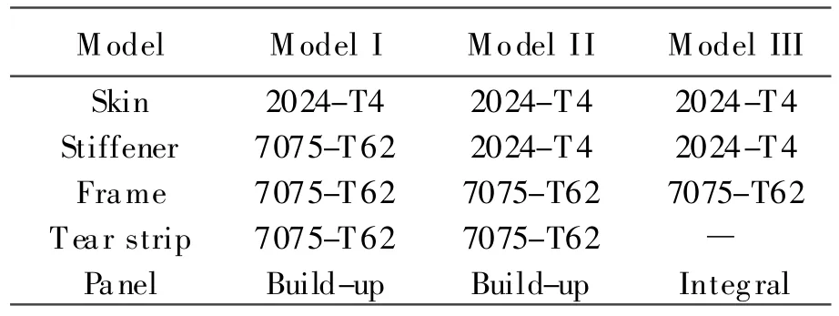
Table 2 Differences of FEMs
The nonlinear structural analysis is performed by using MSC- MARC. The simulation includes the large displacement,the material plasticity property and the contact relation between multiple deformable bodies.
The doublers are added into FEM to simulate the elastic support on the two side edges.The skin,the stiffeners,the frames,the shear clips,and the doublers are all modeled as shell elements located at the mid-surface of these components.The gap between two components is equal to the sum of half the thickness of one component and the othercomponent. These components are restrained to contact each other.
All the nodes on one end of the panel are fixed in all six freedom degrees.On the other end ofthe panel, an RBE2 rigid body element connects the nodes to a single node,and an enforced displacement of 5 mm in the longitudinal direction is applied to this node.The longitudinal edges ofthe panel are fixed in the lateral directions, but are free to the slide in the longitudinal direction.
Model I and Model II are modeled by using 28 triangular plate elements,9 505 quadrilateral plate elements and 156 CBAR elements.And they have 49 983 freedom degrees. ModelIII is modeled by using 4 triangular plate elements,6 162 quadrilateral plate elementsa and 34 CBAR elements.And it has 31 582 freedom degrees.
In the progress of finite element analyses,the loading speed is controlled by time-step and the self-adaptive loading method is used. The total time is 1 s,and the minimum and maximum time steps are 0.05 and 0.1 s.
4 RESULTS AND DISCUSSION
Compared the experimentalresults with finite element results, FEMs are validated to obtain a reliable simulation.Then,the damage load and the damage mode of the integral panel are explored in FEM.
4.1 Experimental results
In the experiment,it is observed that the panel is always upright and the skin effectively absorbs the compression load when the load is smaller. However,the skin appears buckling with the increasing of the load,and the loadcarrying capacity of skin between stringers becomes weaker at the same time.So,the load is absorbed by the stringers and the skin near them.When the load is close to the damage value,the coupling between the bending and the torsion occurres on the stringers,so the stringers are bending failure,as shown in Fig.4(a).The buckling wave of the panel is asymmetrical with respect to the middle stinger.The displacement of the skin is enlarged by the buckling wave crossed the bending stringers,and the whole panel is damaged,as shown in Fig.4(b).
Fig.5 shows the load-displacement curves of 4 strain gages located on the top-edge and the middle of the 1# test specimen. The panel appears buckling in some places when the topedge displacement is 0.4 mm,and the panel is damaged when the top-edge displacementis 2.6 mm,and the maximum displacement of panel is 8.9 mm.
The experimental results of three test specimens are given in Table 3. The average maximum axial compression load is 137.3 kN,and the top-edge displacement is 2.57 mm.
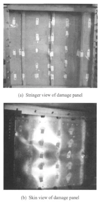
Fig.4 Stringer and skin views of damage panel
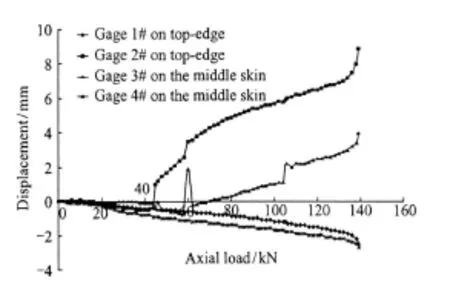
Fig.5 Top-edge displacements from 4 typical strain gages of applied axial load
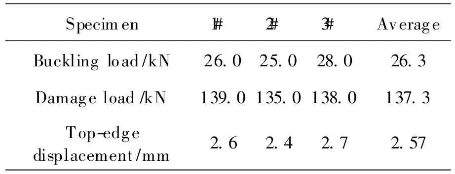
Table3 Experimental results
4.2 FEM validation
The computational buckling coefficient is 0.063 964, so the top-edge displacementis 0.32 mm which is close to the experimental result. The axial compression load curve of Model I is shown in Fig.6 and the comparison of the experimental result is listed in Table 4.
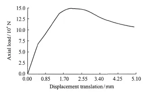
Fig.6 Axial load of top-edge displacement of Model I
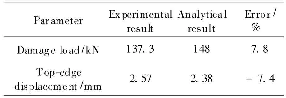
Table4 Comparison of experimental and analytical results
Table 4 shows that the critical axial compressive load is148 kN from the finite element calculation,which is slightly larger than that of the test result. The reasons for the inconsistency of the damage load are discussed as follows:
(1)Rivet holes weaken the loading capability of the build-up panel but they cannot be realized in FEM.
(2)The specimens must have some initial imperfections which are also not considered in FEM.
The specimen damage photo(Fig.4)shows that the damage mode(buckling waves cross the stringers on oblique angle)is the same as the failure picture(Fig.7)from the finite element calculation.
The comparison indicates that FEM is suitable for the failure mode simulation of panel and gives a reliable computational result.
4.3 Comparison of FEMs
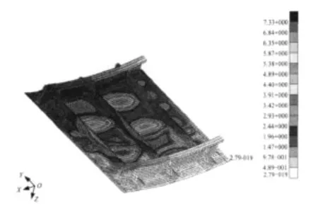
Fig.7 Failure displacement contours for Model I
Because the stringer material on the tested build-up panel is different from thatofthe integral panel,model IIis built by using the same material as the integral panel.So the comparison between Model II and Model III is based on the same condition of the weight,the material and the overall size.
The finite element analysis shows that the maximum displacements of stringers in Model II and ModelIIIare 7.3 mm and 5.5 mm,respectively.The integral stringers do not appear significant bending in the simulation, and buckling waves do not cross the stringers which is different from that of the build-up panel.So,the damage mode of the integral panel is that the skin becomes destabilizing damage when the stress exceeds the yield level.
The comparison data are listed in Table 5,and R is the ratio of the two preceding values.There is only 9%gap of the buckling coefficients,and the buckling loads of these two panels are almost the same. At the stage of the postbuckling,the damage mode of the integral panel is different from the build-up panel.The former is that the stress of the skin exceeds the yield level,and the latter is that the buckling waves cross the stringers.Compared with the build-up panel,the critical compressive load of the integral panel is increased by 18.4%,and the top-edge and the maximum displacement of the panel are nearly the same.So,it indicates that the integral panel has a better loading capability than the build-up panel.

Table 5 Comparison of two panels
5 STRUCTUREOPTIMIZATION OF INTEGRAL PANEL
The parameters of the integral panel are roughly fixed and expected to be optimized.The parameter model is built by using PATRAN Command Language(PCL),and the optimization is carried outin iSIGHT[8]integrated with PAT RAN.
The experimental results reveal thatthe compression load acts mainly on the skin and the stringers.Therefore,dimensions of the skin and the stringers are optimized to make the structure lighter at the same axial compressive loading level.
Fig.8 shows six design variables of the panel.The computational cost is so large for the nonlinearproblem. Therefore, the quadratic response surface model[9-10]is introduced to efficiently solve the numerically computational noise problem and decrease the computation time.
Design of experiment (DOE) in the optimization uses Latin Hypercubes technique and has 200 sample points.The multi-island genetic algorithm and sequential quadratic programming are selected.The multi-island genetic algorithm is used to search the best solution in a large range,and the coupling effect among multivariables is also considered. The sequential quadratic programming is used in the local optimization by FEM to correct the computational resultsand make sure the accuracy ofthe optimization.
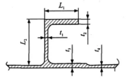
Fig.8 Design variables of skin and stringer
Initial and optimized values are listed in Table 6.The panel mass is lighter by 8.7% than the initial value,and the damage load is larger by 2%.The optimization provides the better design and reduces the whole airplane mass.
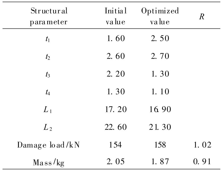
Table6 Comparison of two designs
6 CONCLUSIONS
Based on the experiment of the build-up panel, the analysis and optimization investigations are performed to study the structural response of the curved integral panel subjected to the axial load.The conclusions are drawn below:
(1)The finite element calculation of the build-up panel is validated to agree well with the experimental results up to post-buckling,and the reliable FEM of the integral panel is established.
(2)Analytical results show that the damage mode of the integral panel is the skin stress exceeding the yield level. The detailed comparisons between the build-up and the integral panel show that the kind of integral panel has a better loading capability than the build-up panel,and the maximum axial load is increased by 18.4%.
(3)Based on the quadratic response surface model of the integral panel, the multi-island genetic algorithm and the sequential quadratic programming are used to optimize the structural dimensions.After the optimization,the mass is reduced by 8.7% but the structural strength remains almost the same.It gives an optimum design of the integral panel.
[1] Munroe J,Wilkins K,Gruber M.Integral airframe structures (IAS)—validated feasibility study of integrally stiffened metallic fuselage panels for reducing manufacturing costs[R].N ASA/CR-2000-209337,2000.
[2] Pettit R G,Wang J J,Toh C.Validated feasibility study of integrally stiffened metallic fuselage panels for reducing manufacturing costs[R].N ASA/CR-2000-209342,2000.
[3] Chen Chuin-Shan,Wawrzynek P A,Ingraffea A R.Crack growth simulation and residual strength prediction in airplane fuselages[R].N ASA/CR-1999-209115,1999.
[4] Pettit R G,Newman J C,Domack M S.Crack turning damage tolerance approach for integrally stiffened structure[C]//19th ICAF Symposium.Edinburg,UK: [s.n.],1997:819-830.
[5] Cui Degang.Handbook of structural stability design[M]. Beijing: Publishing House of Aircraft Industry,1996:10-11.(in Chinese)
[6] V ercammen R W,Ottens H H.Full-scale fuselage panel tests[R].N LR-TP-98148,1998.
[7] M SC software corporation. M D nastran 2006 implicit nonlinearuser guide[M]. USA: MSC Software Corporation,2006.
[8] Koch P N,Evans J P,Powell D.Interdigitation for effective design space exploration using iSIGHT[J].Journal of Structural and Multidisciplinary Optimization,2002,23(2):111-126.
[9] Giunta A,Wojtkiewicz J,Eldred M.Overview of modern design of experiment methods for computational simulations[R].AIAA 2003-0649,2003.
[10]Yu Xiongqing,DingYunliang.Multidiscoplinary design optimization a survey of its algorithms and applications to aircraft design[J].Acta Aeronautica ET Astronautica Sinica, 2000,21(1):1-6.(in Chinese)
——生态学
 Transactions of Nanjing University of Aeronautics and Astronautics2010年4期
- Transactions of Nanjing University of Aeronautics and Astronautics的其它文章
- 微型叶轮机械联合试验台设计
- 飞机除冰液对高性能混凝土抗冻性的影响
- 纳米二氧化钛吸入对小鼠肺部和血清生化指标的影响
- 染料敏化太阳能电池用聚偏氟乙烯 /丙烯酸酯互穿网络基凝胶聚合物电解质的制备与性能表征
- 航班进场调度的改进捕食搜索算法
