A guidance and control design with reduced information for a dualspin stabilized projectile
Yu Wang, Jiyan Yu, Xiaoming Wang, Jia Fangxiu
Intelligent Ammunition Technology National Defense Key Discipline Laboratory, Nanjing University of Science and Technology, Nanjing, Jiangsu, 210094,China
Keywords:Spin-stabilized projectile Reduced information Path-following control Extended state observer Coupled nonlinear system Input saturation
ABSTRACT In this paper,an integrated guidance and control method based on an adaptive path-following controller is proposed to control a spin-stabilized projectile with only translational motion information under the constraint of an actuator, uncertainties in aerodynamic parameters and measurements, and control system complexity.Owing to the fairly high rotation speed,the dynamic model of this missile is strongly nonlinear, uncertain and coupled in pitch, yaw and roll channels.A theoretical equivalent resultant force and uncertainty compensation method are comprehensively used to realize decoupling of pitch and yaw.In response to the strong nonlinear and time-varying characteristics of the dynamic system, the quasi-linear model whose parameters are obtained by interpolation of points selected as the segmentation points in the trajectory envelope, is used for calculation in each step.To cope with the system uncertainty caused by model approximation,parameter uncertainty and ballistic interference, an extended state estimator is used to compensate the output feedback according to the test ballistic angle.In order to improve the tracking efficiency and ensure the tracking error convergence with only translational motion information, the virtual guide point, whose derivative is deduced according to the Lyapunov principle, is calculated in real time according to the projection relationship between the real-time position and the reference trajectory,and a virtual line-ofsight angle and the backstepping method are used for the design of the guidance and control system.In order to avoid the influence of control input saturation on the guidance and control performance due to the actuator limitation and improve the robustness of the system, an anti-saturation compensator is designed according to the two-step method.The feasibility and effectiveness of the path-following controller is verified through closed-loop flight simulations with measurement, control, and condition uncertainties.The results indicate that the designed controller can converge to the reference path and evidently decrease the distance between the impact point and target under different uncertainties.
1.Introduction
To satisfy the requirements of missions conducted on modern and future battlefields necessitating a high strike precision and low collateral, many academic and industrial advances in smart munitions have been achieved over the past four decades [1-3].Compared with traditional missiles, spin-stabilized smart munitions, such as course correction fuses (CCFs) [4] and precision guidance kits (PGKs) [5], can retrofit existing unguided munitions with low-cost guidance fuses and reduce drag attributable to the absence of stabilizing surfaces.Hence, spin-stabilized smart munitions have become an important research area in the military domain.
Due to the characteristics of aerodynamic coupling nonlinearity,gyro stability,Magnus effect,trajectory bending et al.,the guidance and control of dual-spin projectile is essentially a multi-input and multi-output system control problem under the conditions of strong coupling, nonlinearity and uncertainty.
The modeling of input-output response relationship is the basis of decoupling control.Aiming at the problem of motion coupling modeling between pitch and yaw channels of twin-rotating projectile, scholars have studied the angular motion, translational acceleration and landing point response respectively.Costello et al.[6] developed a dual-spin projectile, seven degree-of-freedom(7DOF) dynamic model.Ollerenshaw [7] and Fresconi [8]analyzed the swerve response of spin-stabilized projectiles to control the mechanism inputs and demonstrated that the phase shift of the swerve response is close to 180°(°) when the control mechanism is located near the projectile nose.Chang [9-11]explored the dynamic response to a control input by considering the coupled effect of canard control and gravity and concluded that the phase shift can vary substantially with different deflection angles of canards during guidance and control processes.Moreover,Wang et al.[12,13]elaborated on the spin properties of a weapon’s forward and aft parts and their influences on the weapon trajectory.In addition, Sˋeve et al.[14] established an approximating quasilinear parameter-varying (q-LPV) model of a class of spinstabilized canard-controlled guided projectiles and analyzed their stability and pitch/yaw dynamics using this model.
The three types of projectile guidance and control strategies most often considered in guided munitions are trajectory shaping,trajectory prediction and trajectory or path tracking.
Theodoulis [15] designed an autopilot and a gravitycompensated proportional guidance algorithm.However, the drawback of trajectory shaping is its high energy expenditure,which can produce undesired actuator saturations for an energyinefficient spin-stabilized projectile [16].Compared with the other types of guidance and control,trajectory prediction requires a lower control effort and smaller updating frequency, and thus,many studies have focused on this aspect.For example, Frank Fresconi [17] derived a guidance and control strategy of a canardcontrolled fin-stabilized projectile based on impact point prediction that enables precision and trajectory shaping with reduced sensor and actuator requirements.Furthermore, an image-based guidance and control algorithm was formulated directly using feedback from a strap-down detector and roll angle sensors for small-diameter spin-stabilized projectiles [18].In addition, Yi Wang et al.[19] proposed an impact point deviation prediction method based on perturbation theory and deduced the phase lag of the swerve response for correction control.However, trajectory prediction strategies require a fair amount of computing power and a high model fidelity, which are difficult to attain for low-cost volume-constrained and cross-coupled munitions.Steven Tipan et al.[20] carried out decoupling and autopilot design of rotationally stable guided projectile by nonlinear dynamic inversion and time scale separation.Based on the q-LPV model and antisaturation compensation method, Thai et al.[21] designed a gain scheduling autopilot for canard type rotary stabilizer with control input saturation.Gagnon et al.[22] employed a path-following guidance law by directly comparing the positions along the y and z axes based on the shell position along the x axis.However, the guidance and control performances were less impressive in presence of wind velocity variation and velocity variation.Gandolfo et al.[23] proposed a path-following controller for a quadrotor helicopter in which the speed is a dynamic profile varies with geometric requirements of the desired path.Costello et al.[24]proposed an optimizing control strategy for power kites flying crosswind to follow a reference path using position measurements only.However, these control strategies are not suitable for a coupled nonlinear high-dynamic system with uncertainties such as a guided spin-stabilized projectile.
To deal with the system uncertainty caused by external interference, inaccurate modeling, measurement and control system error, researchers have carried out a lot of research for different research objects.Gruenwald et al.[25] designed an extended reference model adaptive controller to suppress the system uncertainty caused by the dynamics of the actuator of the rudder controlled guided projectile.Based on adaptive backstepping sliding mode control method, Jegarkandi et al.[26] designed an integrated guidance control law considering actuator failure.Considering the saturation of control input, Wang et al.[27]designed the guidance and control system of sideslip and turn control missile based on dynamic surface control and linear extended state observer.Zhen et al.[28]used the dynamic surface control method to design a fully nonlinear controller with observers to control the sideslip turn missile with high coupling,high nonlinearity and limited uncertainty.
For the control of nonlinear systems with mismatched errors,Min Huifang [29] designed a composite controller suitable for higher-order nonlinear systems with mismatched disturbances by introducing disturbance observer (DO) and finite-time control method without any additional assumptions on the nonlinear term of the system.Min et al.[30] proposed a finite-time control algorithm suitable for nonlinear systems with unknown parameters and external disturbances.This method compensates the serious uncertainty caused by unknown parameters through adaptive control method, uses disturbance observer to eliminate the external disturbances with clear upper bound, and then designs a composite adaptive state feedback controller based on finite-time adaptive control and backstepping method.Yang et al.[31] proposed a finite-time control algorithm based on nonlinear integral sliding mode control to deal with the control problem of secondorder multi-agent systems with mismatched and matched disturbances.Zhou et al.[32]adopted fuzzy logic system,combined with specified performance function (PPF) and potential barrier Lyapunov function(BLF),designed adaptive fuzzy timing control for pure feedback interconnected nonlinear system with full state tracking error constraint.Hu et al.[33] proposed a robust adaptive fuzzy MIMO controller design method for nonlinear non-minimum phase systems with parameter uncertainties and unmodeled dynamics.Shafei et al.[34] developed a DO-based hybrid control system, combining the optimal control law based on the statedependent Riccati equation with the DO-based second-order sliding mode controller, which achieved the goal of reducing the control workload while improving the robustness of the system.
However, these guidance and control methods require substantial quantities of measurement information, such as those acquired by accelerators and gyroscopes,which is greatly challenging for low-cost and volume-constrained projectiles.
To overcome these limits of multi-sensor, high model fidelity and large amount of computing power needed,a novel IGC method using position measurements only, based on path tracking guidance is proposed in this paper by modelling the guidance and control as a whole system.To summarize, this paper has the following innovative points:
(1) The virtual guide point is proposed and a path following algorithm with virtual line of sight is deduced using the backstepping method and Lyapunov theory, to reduce the overload requirement and achieve the uniform convergence of position and velocity direction deviations.
(2) An extended state observer(ESO)is designed to estimate and compensate for uncertainties caused by model approximation, parameter uncertainty and ballistic interference.
(3) An anti-saturation compensator is designed according to the two-step method, to avoid the influence of control input saturation on the guidance and control performance due to the actuator limitation and improve the robustness of the system.
The remainder of this paper is organized as follows.First, the mathematical model of the IGC system composed of a dynamic spin-stabilized projectile model and a path-following error model is formulated.In particular, the dimensions of the dynamic model corresponding to angular motion are pruned by linearizing the pitching and yawing motions to adapt the design of the IGC system containing translational motion information measured by GPS or accelerator sensors.Then, the IGC algorithm a are designed based on the back-stepping method and Lyapunov theory.Finally, the feasibility and effectiveness of the algorithm is verified through closed-loop flight simulations with measurement, control, and condition uncertainties.
2.Problem formulation
In this section a novel 3D dynamic model of a spin-stabilized projectile is OxIyIzIestablished first, and then the path-following error model is established in the reference path coordinate system.Finally, the IGC model is formulated by integrating these models.
2.1.Coordinate system definition
First, the inertial coordinate, velocity coordinate GxVyVzV, noroll coordinate GxNyNzNand reference path coordinate PRxRyRzRframes are defined as shown in Fig.1.The origin of the inertial coordinate is the launch point, and the xIaxis is directed a O long the line of fire and is tangent to the earth surface.The origin of the velocity coordinate and no-roll coordinate G is the projectile’s center of mass.The xVaxis is directed along the projectile’s velocity vector v→, and the direction of xNis along the axis direction of the projectile x→.The origin of the reference path coordinate PRis the virtual wizard point of the nominal trajectory, and the xRaxis is directed along the tangent line of the reference trajectory.The y axes of these coordinates are directed vertically upward.θR, ψRrepresent the inclination or deflection of the reference path respectively.
2.2.7DOF dynamic projectile model
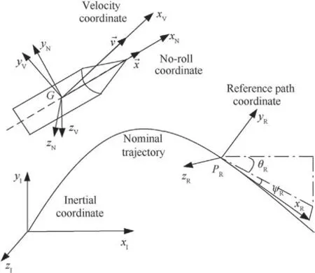
Fig.1.Definitions of the coordinate systems.
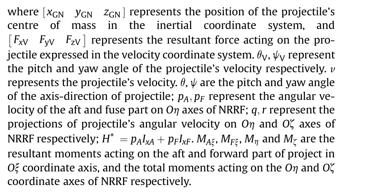
The nonlinear model of the projectile is composed of translational (expressed as Eqs.(1) and (2)) and attitude dynamic(shown as Eqs.(3)and(4))equations resulting from Newton’s and Euler’s laws.Eq.(1)are given in the velocity reference frame(VRF)and Eq.(4) are given in the no-roll reference (NRRF) frame as in Ref.[13]:
2.3.Simplified dynamic model
Since the flight attitude of the projectile has obvious influence on the aerodynamic force (moment) of the projectile, there is a strong coupling between the angular motion and the translational motion.In order to deal with the model error caused by unknown angular motion parameters, the linear differential equation of the angle of attack is derived according to the 7-degree of freedom equation as the angular motion estimator is substituted into the kinematic model,so as to derive the simplified dynamic model for the subsequent guidance and control system design.
With reference to the equivalent canard model proposed in Ref.[12], the controllable force and moment can be created by equivalent canards in NRRF as follows:

As the equivalent canard model of a dual-spin projectile expressed in Ref.[13]in detail,when γE=0,the force generated by the maneuver canards is in the yN-direction; When γE=90o, the force generated by the maneuver canards is in the zN-direction.For simplicity, the control inputs (i.e., the equivalent deflection angles of the pitch and yaw rudder)are recorded as u =■δyδz|T,which can be expressed as δy=δCEcos γE,δz=δCEsin γE.
Considering the aerodynamic forces, gravity and control force,the resultant force for a spin-stabilized projectile with canards in the velocity coordinate system can be approximately calculated as follows:
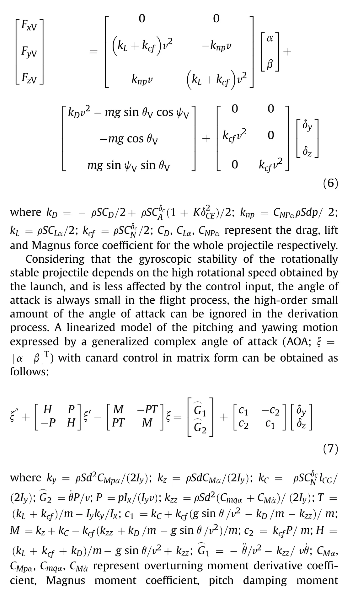

As the gradients of parameters in Eq.(7) are small, it is reasonable to assume these parameters as constants in a short time period.To analyse the relationship between angular motion and canard control, the Laplace transform of [α β]Tshown as Eq.(8)can be obtained by several transformations on Eq.(7).


2.4.Path-following error model
To design the path-following algorithm, the path-following error,which is consist of the position following error related to x1and the velocity direction following error related to x3, should be modelled primarily.To compare the projectile’s trajectory with the reference path,a virtual wizard point on the reference path should be chosen firstly.In the existing literature,the virtual wizard point is usually retrieved by flight time or down range.However, the motion on the velocity orientation of these virtual wizard is compulsive, which leads to the tracking performance of position error on the velocity direction cannot be guaranteed.To solve this problem,the virtual wizard in this article is retrieved based on the arc length of reference path aL.Recording the position, inclination and deflection angle of virtual wizard point PRas xP, yP, zP,θPand ψPrespectively.
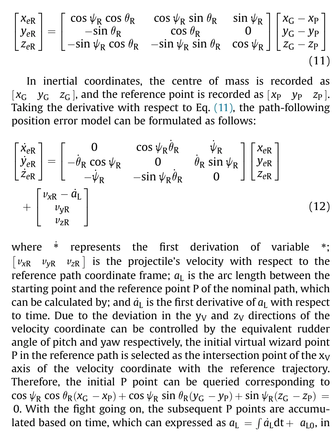
To follow the nominal trajectory,the path-following error model is established in the reference path coordinate system.The distance between the position of the projectile’s centre of mass G and the reference point P along the nominal trajectory achieved by the virtual wizard method is defined as the path-following position error.Because the position information in the inertial coordinate frame can be measured by GPS,the path-following position error in the reference path coordinate system can be calculated by transformation, as shown as:

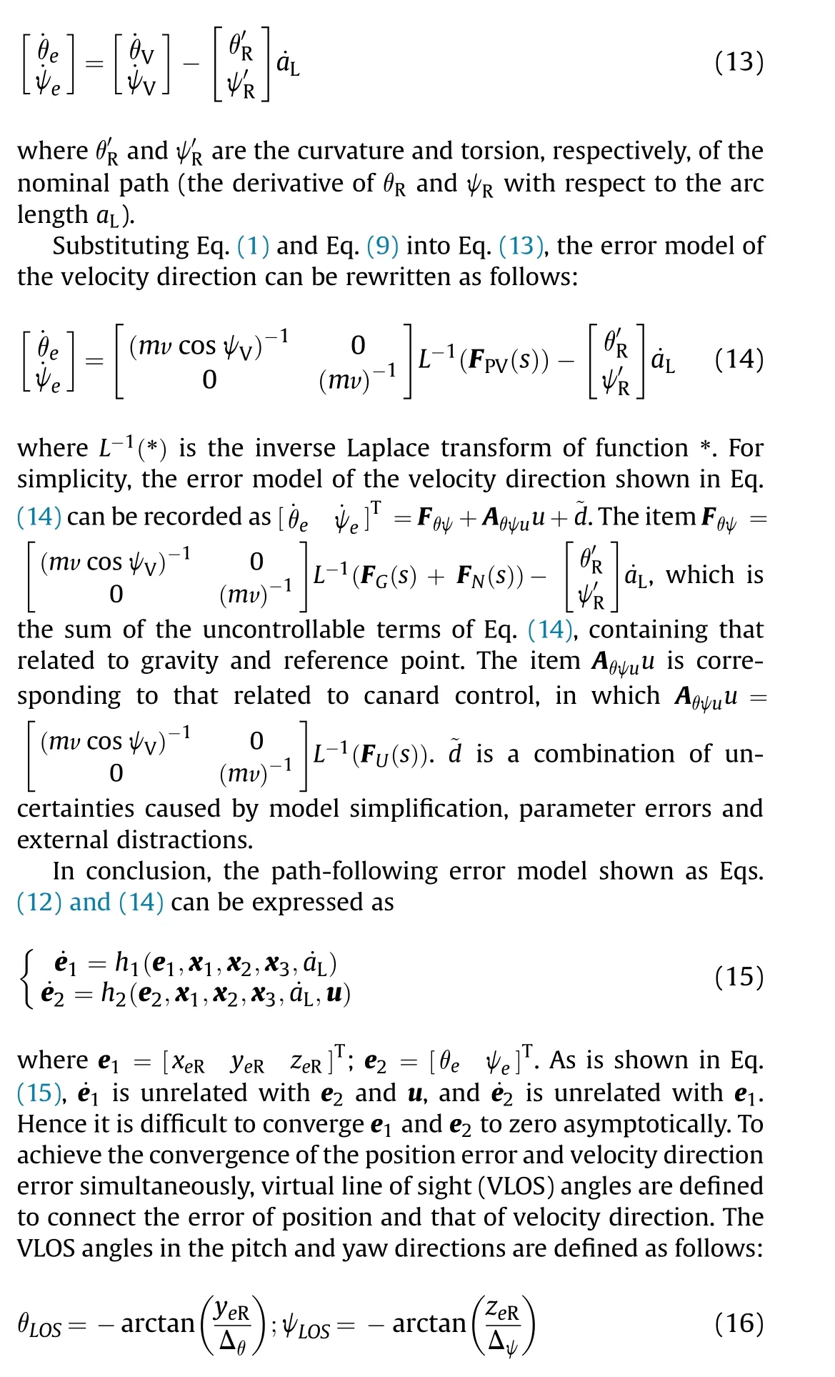
where arctan(·)is an arc tangent function;Δθand Δψare the lineof-sight distances in the pitch and yaw directions,respectively;and Δθand Δψare positive constants whose values are related to the weights of the position and velocity direction errors in the design of the controller.
The derivatives of the VLOS angles with respect to time can be expressed as follows:
Define the complex velocity direction following error e3=[ξθξψ]T= [θe-θLOSψe-ψLOS]T, and then substitute Eqs.(16)and (17) into Eq.(15), the path following error can be established as:
3.Path-following algorithm
Without information on angular motion, only translation motion is measured by GPS sensors or accelerometers.The pathfollowing controller is designed by the back-stepping method and Lyapunov theory in two steps corresponding to the velocity direction and position following errors, respectively.To reduce the overload requirement, the error in the velocity direction is considered with the position-following error by the virtual line of sight (VLOS) when the following algorithm is designed.
3.1.Controller design steps
The path-following controller is designed by the back-stepping method and Lyapunov theory in two steps.
3.1.1.Step 1: velocity angle control
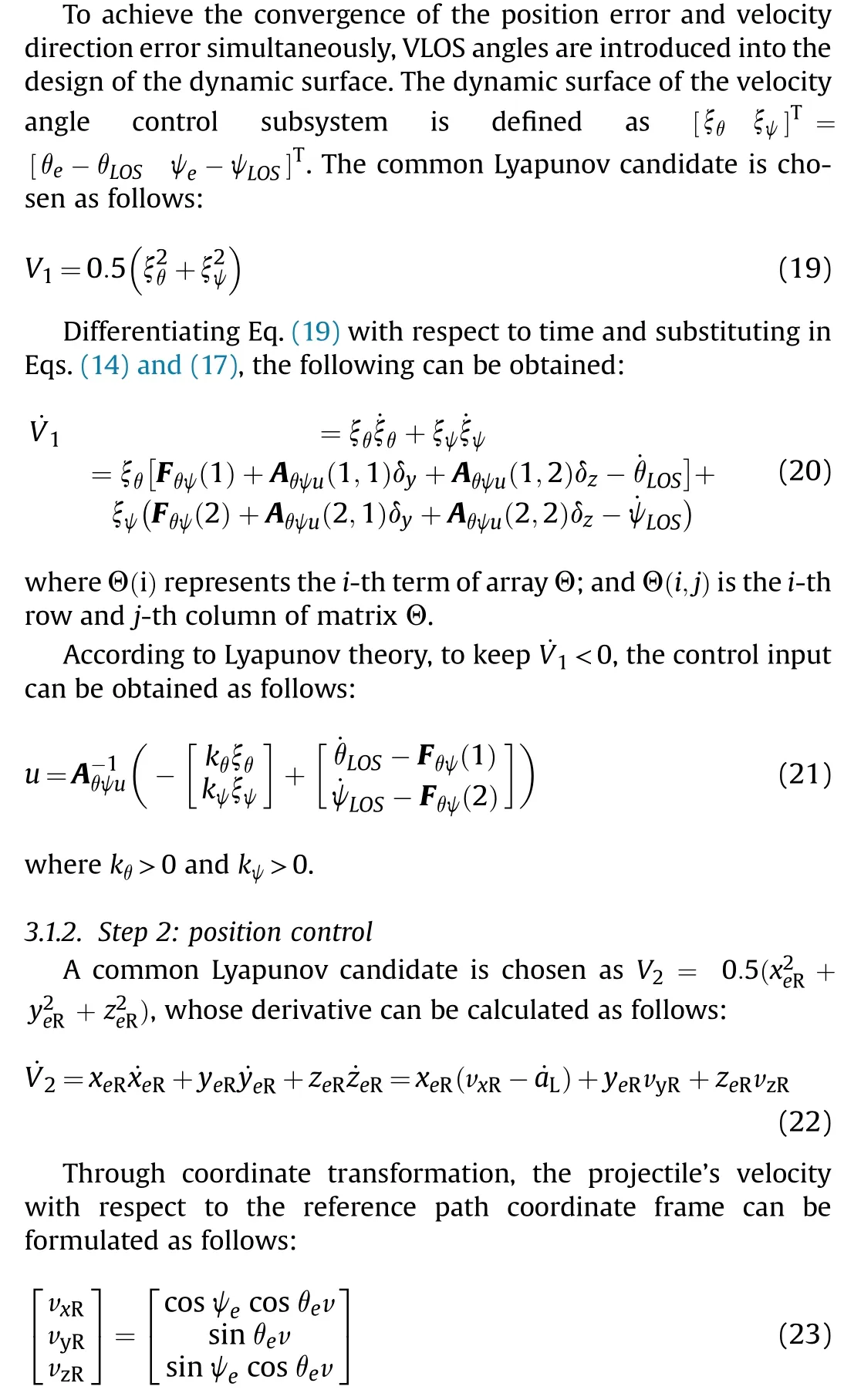
Considering Eqs.(22)and(23),the moving velocity of the virtual wizard point ˙aLis chosen as follows:

3.2.Stability analysis
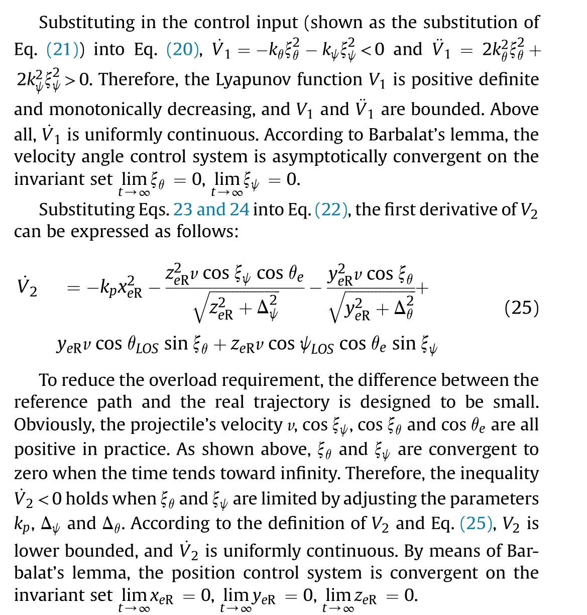
Above all, it is obvious that the first derivative of V3, whose definition is V3= V1+ V2, is negative and continuous.Therefore,the following errors in the position and velocity directions(xeR,yeR,zeR, ξθand ξψ) are convergent to zero when time approaches infinity.
3.3.ESO-based path-following IGC design
Considering the uncertainties caused by linearization and measurement errors, an ESO is designed to estimate and compensate for these uncertainties as a whole.A function block diagram of the ESO-based path-following IGC is shown in Fig.2.

Fig.2.Function block diagram of the ESO-based path-following IGC.
After initializing the system,the translational information of the projectile obtained by GPS sensors or accelerators is transformed and transferred into the ESO.Then, the uncertainty term and measurement data are estimated and filtered by the ESO.Afterwards, the differences in the position and velocity directions between the reference point and the projectile are used to generate the control output by the aforementioned path-following algorithm.It is worth mentioning that the reference point for the first set of measurement data is found by the time or range rather than the arc length,which is used later,and the arc length s is calculated by integrating ˙s expressed as Eq.(24).
Now, consider the system of [˙θV˙ψV]Tand the uncertainty as follows:
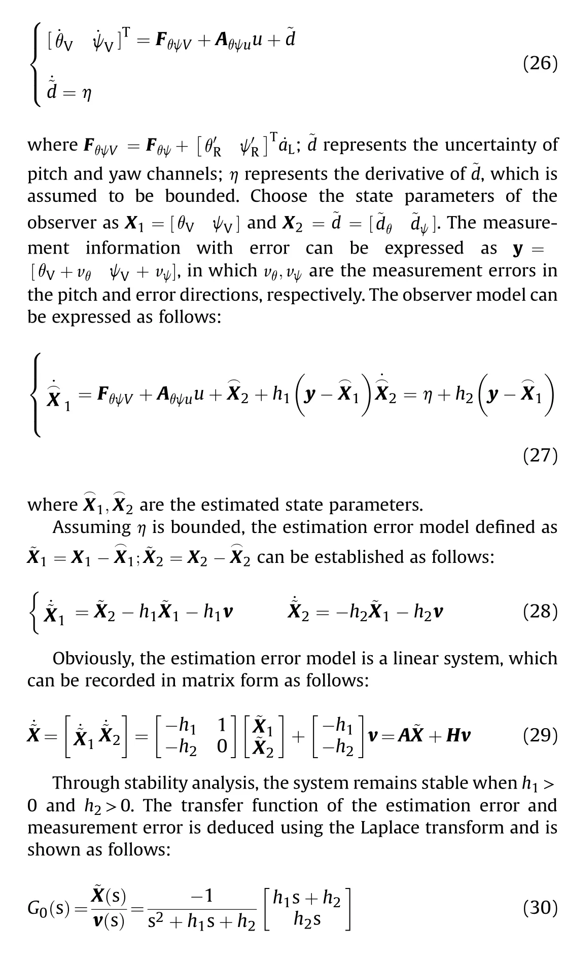
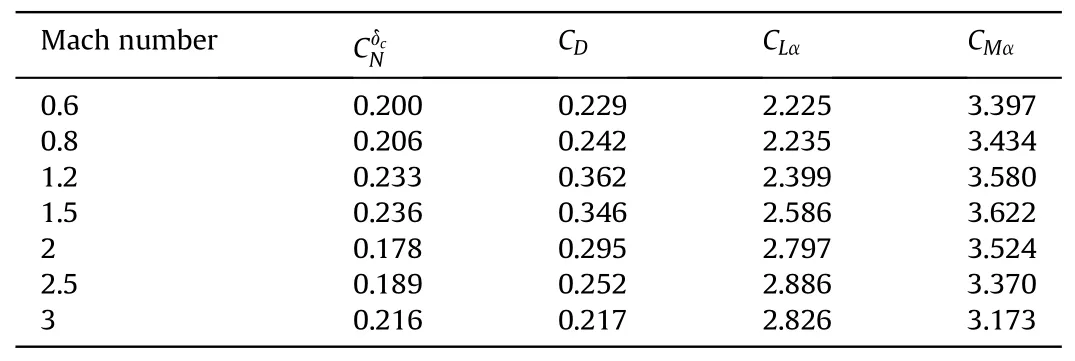
Table 1 Aerodynamic parameters of the projectile.

Table 2 Measurement and control errors.
Substituting h1=εα1and h2=ε2α2into this transfer function,it can be rewritten as follows:
Obviously,when the value of G0(s)approaches zero,the impact of measurement noise on the estimation performance is reasonably ignored.Hence, to maintain system stability and restrain noise in the measured signal, the parameters should be chosen within certain intervals: 0 <ε≪1,α1>0,α1>0.
To prove the estimation accuracy and robustness of the proposed IGC law, the auxiliary state parameters are defined as Z1=ε-1˜X1,Z2=ε-2˜X2and Z =[Z1Z2]T.Substituting Z1and Z2into Eq.(29), an auxiliary system can be obtained:
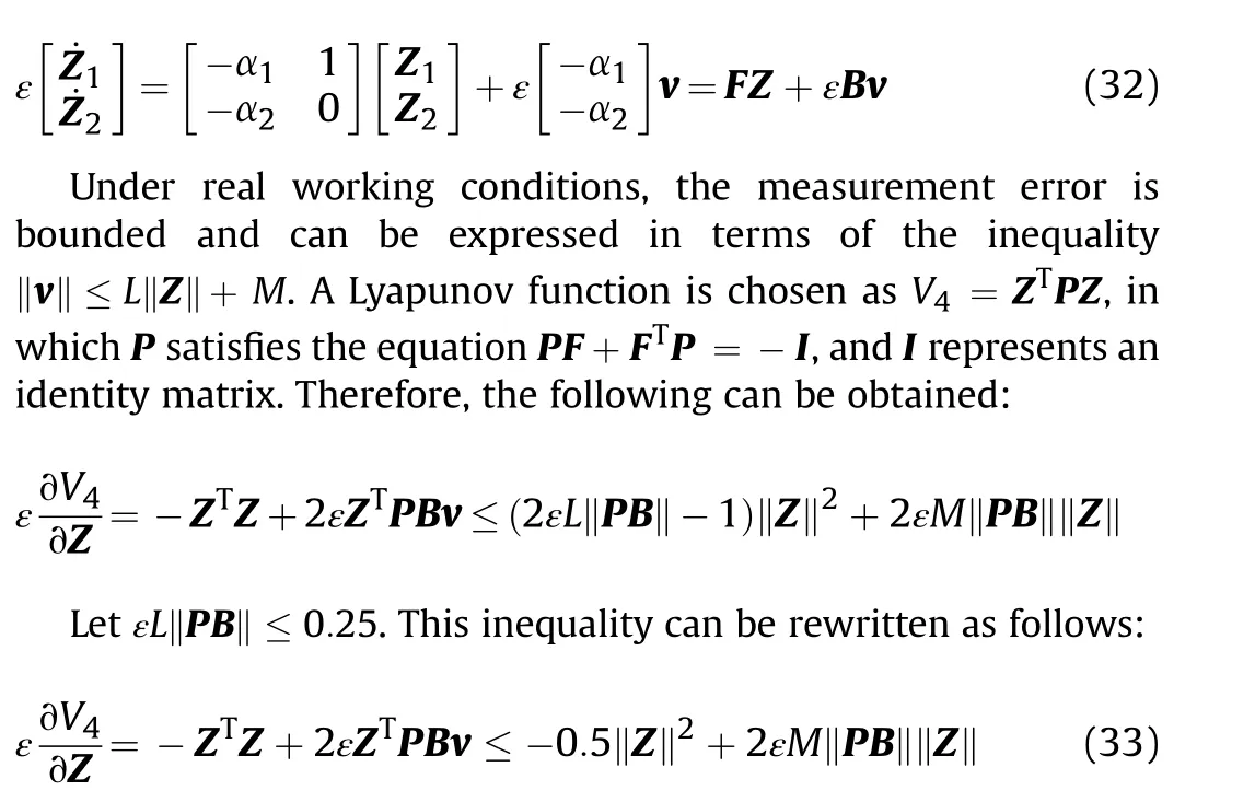
By using Lemma 4.2 and Theorem 4.5 in Ref.[35], ‖Z‖ and the corresponding ‖˜X‖ are ultimately bounded, in other words, there exist positive constants a,k,c that make the inequality (shown as Eq.(34)) reasonable when t ≥0:
where t is the time variable in the observer model.This inequality indicates that Z(t)approaches the boundary εcM exponentially,and the attenuation speed increases with decreasing ε.Accordingly,the error in the estimation ˜X can converge rapidly to a small value when ε is sufficiently small.To avoid the peak phenomenon caused by an excessively small ε, which has serious impacts on the feedback control system,an appropriate value of ε should be chosen to balance the estimation accuracy and the steady performance of the control system.
3.4.Control input saturation
The hyperbolic tangent function is used to approximate the saturation performance of the control input, and the control input considering actuator saturation can be expressed as:

Table 3 Launch and atmospheric parameters under different simulations.
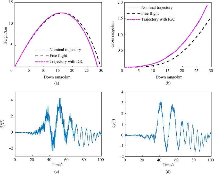
Fig.3.Performance of the proposed IGC law without aerodynamic parameter errors: (a) Down range vs.height; (b) Down range vs.cross range; (c) Deflection angle of the pitch rudder; (d) Deflection angle of the yaw rudder.
δsupindicates the maximum value of the control input.Substituting into Eq.(21), it can be obtained that under the condition of maintaining the stable convergence of the control system, the control quantity u considering the control input saturation can be expressed as:
Considering the limited manoeuvrability of the spin-stabilized projectile, the occurrence of saturations cannot be ignored.To avoid the influence of saturations on guidance effect, an antiwindup compensator is designed by two step method.The first step is the tracking control method obtained by the trajectory tracking method designed in the previous section.The second step is to design the anti-saturation controller using LMI method.
4.Simulations and results
In this section,to verify the performance of the proposed pathfollowing IGC law with measurement noise, wind perturbations and control errors are simulated using a 155 mm projectile with a roll-decoupled CCF whose parameters are shown in Ref.[36].The projectile is maneuvered by fixed canards whose deflection is 10°(δCE= 10o), and the equivalent direction of the control force γEcorresponds to the rolling angle of the CCF.The aerodynamic parameters of this projectile are shown in Table 1.Considering the hard constraint on the control by limiting the equivalent deflection to 10°,the control command γEcan be formulated according to the equivalent canard model asTo reduce the required overload,a nominal path is generated by a trajectory simulation.To verify the performance of the proposed IGC law, a full system simulation is executed with normally distributed measurement and control errors,whose parameters are shown in Table 2.The parameters γEand γOrepresent the input and output,respectively,of the actuator,whose delay time is set as 0.2 s.The launch and atmospheric wind conditions in addition to the coincident coefficients of the different simulations are listed in Table 3.
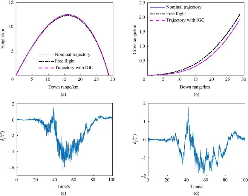
Fig.4.Performance of the proposed IGC law with aerodynamic parameter errors:(a)Down range vs.height;(b)Down range vs.cross range;(c)Deflection angle of the pitch rudder;(d) Deflection angle of the yaw rudder.
To verify the IGC law, the free flight and controlled trajectories with the same launch and atmospheric parameters are compared with the nominal trajectory.When the aerodynamic parameters of the nominal and controlled trajectories are the same, the performance of the proposed IGC is shown in Fig.3,and the parameters of the controlled trajectory correspond to those of No.1 in Table 3.Plots of the height and cross range versus the down range are shown in panels Fig.3(a)and(b),respectively,and control output in pitch and yaw δyand δzare shown in Fig.3(c)and(d).These figures demonstrate a good path tracking performance of the proposed IGC law without aerodynamic errors between the nominal and real flight trajectories in both the down-range and the cross-range directions with a fixed canard deflection of 10°.According to the principle of course correction,the actuator nearly stops the service when the command corresponds to circular motion,such as during 0-20 and 92-103 s.Owing to measurement noise within the system, some errors and disturbances are observed in the command angle γE.In addition,the miss distance of the projectile controlled with the proposed path tracking IGC law under these conditions is 0.215 m.
Similarly, to analyse the path tracking performance of the proposed IGC law with measurement noise, control errors and aerodynamic parameter errors, the trajectories with the parameters of No.2 in Table 3 both with and without a guidance and control system are simulated and compared in Fig.4.The aerodynamic parameters used in the IGC law are the same as those of the nominal trajectory rather than the controlled trajectory.It is obvious that the trajectory controlled with this IGC law gradually approaches the nominal path trajectory in the 3D space.The miss distance of the controlled projectile under these conditions is 3.6 m, which is much smaller than that of the corresponding free flight trajectory (820 m).
Furthermore, to verify the performance of the path-following algorithm proposed in this paper, the trajectory controlled by the IGC law in this paper,that controlled by the trajectory tracking law(recorded as TT,proposed in Ref.[21])are simulated and compared in Fig.5.The parameters of launching condition, measurement noise, control errors and aerodynamic parameter errors are listed No.2 in Table 3.The guidance and control systems of IGC and TT start working from 25 s after launching.The 3D path of reference trajectory and trajectories controlled with IGC and TT algorithms are compared in Fig.5(a) and (b).The pitch and yaw deflection angles of IGC and TTcontrolled trajectories are compared in Fig.5(c)and(d).In the TT algorithm,the virtual wizard of search is achieved for the real-time projectile’s down range.
As is shown in Fig.5,the trajectory controlled with IGC is closer to the reference trajectory than that controlled with TT algorithm,which illustrate that the tracking performance of IGC is better than TT.The control outputs δyand δzof IGC are changing more smoothly than those of TT, and there is almost no sign mutant especially.Therefore,the manoeuvring capability of IGC algorithm is used more efficiently than TT.Considering the negative effects of control force’s vibration on flight stability and working performance of actuator, a threshold scheme is designed in the guidance algorithms.To reduce the vibration of control output when the real moving trace is almost consistent with the reference path, control output δyand δzare set as zero to stop control.
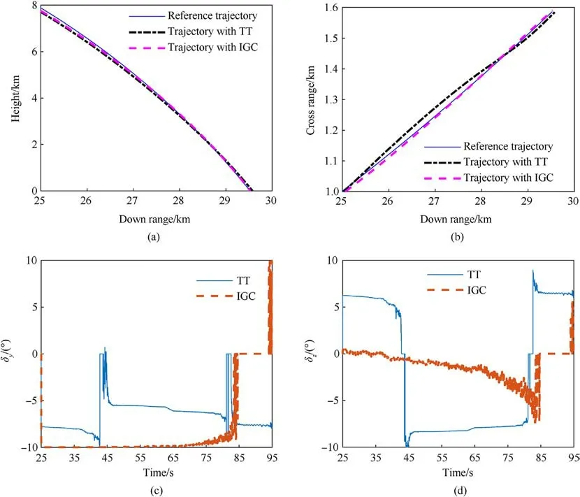
Fig.5.Comparison of the IGC law and TT with aerodynamic parameter errors:(a)Down range vs.height;(b)Down range vs.cross range;(c)Deflection angle of the pitch rudder;(d)Deflection angle of the yaw rudder.
To evaluate the implementation effect of ESO’s uncertainty compensation, the control output of this IGC algorithm with and without ESO are compared in Fig.6(a) and (b) illustrate that path tracking performance of IGC with ESO is better than that without ESO.In Fig.6(c) and (d), it is obviously that the amplitude of deflection angles’ fluctuation with ESO is much smaller than that without ESO.As the cause of control output’s fluctuation is the random uncertainties of measurements and control system, the random uncertainties can be compensated by ESO effectively.
Finally, to verify the robustness of the proposed formulation,Monte Carlo simulations are carried out by considering the influences of various combinations of system uncertainties.Simulations consisting of 200 runs for each experiment are carried out with launching, wind and aerodynamic uncertainties, the parameters of which are listed in Table 4, and the parameters of the measurement and control errors are listed in Table 2.The impact point distributions for the scenarios involving free flight and projectile trajectories controlled by the proposed IGC law after 20 s of simulation are compared in Fig.7.These figures indicate that the adaptive path-following IGC algorithm proposed in this article can evidently improve the precision under different combinations of launching,wind and aerodynamic uncertainties,indicating that the robustness of this law is good.However, owing to the limited manoeuvring capability, the miss distance is relatively large when the difference between the nominal and uncontrolled trajectories is substantial.
5.Conclusions
To solve the problems associated with the guidance and control system of a spin-stabilized canard-controlled projectile with only translational motion information obtained from GPS sensors or accelerators, a novel IGC method based on an adaptive pathfollowing controller is proposed in this paper.To follow a 3D trajectory with 2D control input,a virtual wizard and its derivative are deduced.Considering the limited manoeuvring capability and system stability, VLOS angles are used to achieve the uniform convergence of the position and velocity direction deviations.In addition, using the back-stepping method and Lyapunov theory, a control law is derived with a sliding mode surface established in the reference path coordinate frame and is proven to converge.Moreover, to enhance the robustness of the system under uncertainties in the aerodynamic parameters and measurements and considering the complexities of the control system,an ESO is designed to estimate the parameters and compensate for the uncertainty online.The feasibility and effectiveness of the path-following controller is verified through closed-loop flight simulations considering measurement, control, and condition uncertainties.The results indicate that the designed controller can converge to the reference path and evidently decrease the distance between the impact point and target under different uncertainties.
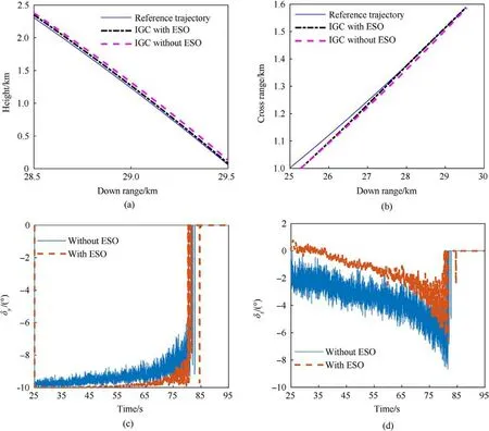
Fig.6.Comparison of control output of IGC with and without ESO:(a)Down range vs.height;(b)Down range vs.cross range;(c)Deflection angle of the pitch rudder;(d)Deflection angle of the yaw rudder.

Table 4 Uncertainty parameters for Monte Carlo simulations.
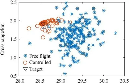
Fig.7.Impact point distributions for uncontrolled and controlled scenarios.
In addition, considering the manoeuvring capability of the spinning stable projectile, the reference trajectory used in this manuscript is mainly obtained based on the theoretical free flight trajectory which can hit or close to the target.How to plan a better normal trajectory, how to handle matched and mismatched disturbances separately,and how to realize cooperative guidance and control for spinning stabilized projectile are our future researches.
Declaration of competing interest
The authors declare that they have no known competing financial interests or personal relationships that could have appeared to influence the work reported in this paper.
- Defence Technology的其它文章
- Explosion resistance performance of reinforced concrete box girder coated with polyurea: Model test and numerical simulation
- An improved initial rotor position estimation method using highfrequency pulsating voltage injection for PMSM
- Target acquisition performance in the presence of JPEG image compression
- Study of relationship between motion of mechanisms in gas operated weapon and its shock absorber
- Data-driven modeling on anisotropic mechanical behavior of brain tissue with internal pressure
- The effect of reactive plasticizer on viscoelastic and mechanical properties of solid rocket propellants based on different types of HTPB resin

