Sandwich structures with tapered tubes as core: A quasi-static investigation
Xinmei Xing , Dehu Sho , Xin Zhng , Umer Shrif , Ngo Sn H , Li Xing ,Jing Zhng ,*, Jing Yi ,**
a School of Civil Engineering, Guangzhou University, Guangzhou, China
b Department of Mechanics and Aerospace Engineering, Southern University of Science and Technology, Shenzhen, Guangdong, China
c School of Engineering, Centre for Innovative Structures and Materials, RMIT University, Melbourne, Australia
d China Southern Airlines Co., Ltd, Shenzhen Branch, Shenzhen, 518000, China
Keywords:Sandwich structure Corrugated tube Tapered tube Quasi-static Energy absorption
ABSTRACT In this article, the experimental and finite element analysis is utilized to investigate the quasi-static compression features of sandwich constructions built with tapered tubes.3D printing technology was utilized to create the hollow centers of the tapering tubes, with and without corrugations.The results demonstrate that the energy absorption (EA) and specific energy absorption (SEA) of the single corrugated tapered tube sandwich are 51.6% and 19.8% higher, respectively, than those of the conical tube sandwich.Furthermore, the results demonstrate that energy absorbers can benefit from corrugation in order to increase their efficiency.Additionally, the tapered corrugated tubes’ resistance to oblique impacts was studied.Compared to a straight tube, the tapered tube is more resistant to oblique loads and has a lower initial peak crushing force (PCF), according to numerical simulations.After conducting a parametric study, it was discovered that the energy absorption performance of the sandwich construction is significantly affected by the amplitude, number of corrugations, and wall thickness.EA and SEA of DTS with corrugation number of 8 increased by 17.4%and 29.6%,respectively,while PCF decreased by 9.2% compared to DTS with corrugation number of 10.
1.Introduction
Lightweight structures [1,2] with significant energy absorption capacity are increasingly in demand in the engineering sectors of aircraft, transportation, and other industries.Due to its many benefits,such as ease of processing,low cost,and lightweight,thinwalled structures are frequently utilized as energy absorbers.Thinwalled tubes’ crashworthiness depends on various factors,including wall thickness, cross-sectional shape, geometric dimensions,and material characteristics[3-6].Among these factors,cross-section shape is crucial.Numerous studies have been done on common cross-sectional shapes such as squares, triangles, and circles[7-9].The results reveal that modifying the cross-sectional geometry of the structures can significantly increase their energy absorption performance[3].
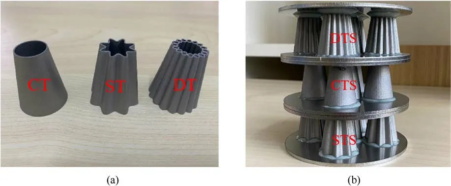
Fig.1.Specimens: (a) Ct, ST and DT; (b) CTS, STS and DTS.

Table 1 Geometric parameters of ST.
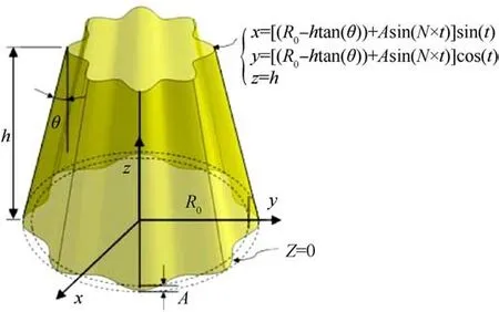
Fig.2.Mathematical model of ST.
In recent years, researchers have created lateral corrugated tubes by adding corrugations to the cross-section of traditional thin-walled tubes and conducted a series of experimental and simulation studies[10-14].For example,Deng et al.[10]fabricated lateral corrugated circular tubes(LCCT),and carried out quasi-static compression analysis and optimization design for the tubes.The results show that the specific energy absorption (SEA) of LCCT increased by 27.91% when compared to the ordinary circular tube,and the SEA of the optimized LCCT increased by 53.65%.However,they discovered that the initial peak crushing force (PCF) of the LCCT was much higher than that of the circular tube.In another study [9], they designed lateral corrugated tubes with a thickness gradient to eliminate this drawback and reduced the PCF by 44.53%.Sadighi et al.[15,16] designed a half-corrugated circular tube with corrugations introduced only at half of the height.This kind of tube exhibited an inverted deformation mode, resulting in increased friction,and a significant increase in crushing force efficiency(CFE),mean crushing force (MCF), and SEA.Li et al.[17] investigated the inversion mode of LCCT when it was mounted upon a profiled rigid die, and found that LCCT produced a more stable inverted deformation pattern and higher energy absorption compared with that of the circular tubes.Furthermore, some studies [18-21] focus on the lateral corrugated square tube (LCST).Li et al.[22] systematically investigated the energy absorption performance and deformation mode of the LCST with a cosine profile.According to the numerical findings,there were five categories for the LCST collapse modes, with the orderly progressive mode (OPM) having the highest crashworthiness.The SEA of LCST was 51.62% better than that of the square tube.To further enhance the tube’s capacity to absorb energy, Li et al.[23,24] designed a multi-cell LCST and studied the crashworthiness of the tube.The results show that the 4-cell LCST with crisscross internal ribs had the best energy absorption and deformation mode, regardless of axial or oblique loading.This conclusion indicates that increasing the number of cells was not always advantageous when various crashworthiness criteria and loading angles were taken into account.In addition,they found that,when compared to triangular and square tubes,the introduction of multi-cell corrugations on circular tubes would achieve better crashworthiness [25].Simultaneously, the parameters of the corrugated tubes have been extensively analyzed[22,26].The findings indicate that the number of corrugations and amplitude played an important role in structural crashworthiness.Reasonable configuration of corrugation number and amplitude would result in a stable deformation pattern and high energy absorption[22].For the unstable deformation of the corrugated tubes,the researchers devised two improvements,adding bulkheads[27]and introducing origami initiators[28],and successfully triggered a reliable progressive buckling failure mode.In summary, the introduction of lateral corrugations 0significantly improved the tube’s capacity to absorb energy but also increased the initial PCF.
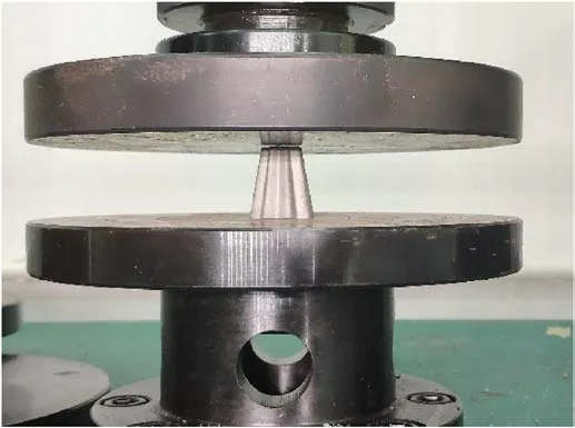
Fig.3.Experimental set-up of the compressive test.
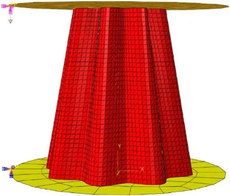
Fig.4.Finite element model of ST.
Numerous studies have shown that tapered tubes have an inherent advantage in reducing the initial PCF [6,9].For example,Asanjarani et al.[7]investigated the tapered tubes of circle,ellipse,square,hexagon,octagon,and rectangle,and found that the PCF of tapered tubes of six shapes was smaller than that of straight tubes under axial loads.In addition, compared with straight tubes,tapered tubes had better crashworthiness under oblique loads[29,30].Straight tubes are more prone to buckling under oblique loads, resulting in poor structural performance.In recent years,axial corrugated tapered tubes (ACTT) have been proposed and studied [31-33].The results show that when compared to conical tubes, ACTT significantly reduced PCF and undulation of load carrying-capacity (ULC), produced a more stable and controlled collapse pattern, but sacrificed energy absorption capacity [33].Furthermore,the wavelength and amplitude were considered to be important parameters influencing the collapse mode and energy absorption of ACTT.Increasing the amplitude or decreasing the wavelength further reduced the PCF and ULC of ACTT, and better prevented the overall buckling [34].Furthermore, the effect of tapered angle and thickness on the oblique impact resistance of ACCT was researched by Alkhatib[29].The results reveal that ACTT with greater thickness and smaller tapered angles offer more energy absorption,and adopting corrugation enhanced the SEA under oblique loads.
Sandwich structures are widely used in transportation, construction, and aerospace industries due to their superior mechanical features, such as high load-bearing capacity, high stiffness-toweight ratio, excellent stability and so on.Different geometries of sandwich cores have been researched, such as truss [35,36], honeycomb[37-39],origami[40],and corrugated[41,42].In the study of corrugated sandwich structures, Zhang et al.[43] investigated the out-of-plane quasi-static compressive behavior of four types of corrugated cores(V-type,U-type,X-type and Y-type core)through experiments and FE simulations.Experiment and simulation indicate that the U-type core, V-type core and X-type core structures show excellent crushing resistance performance and energy absorption characteristics.Bending performance of unidirectionally aligned corrugated core sandwich panels depended on their alignment direction.To improve the drawback, bi-directional sinusoidal corrugated core panels were designed[44,45].The results indicate that the SEA was higher than that of unidirectional corrugated core sandwich panels under bending loads[45],and its collision resistance was also higher than that of unidirectional triangular and sinusoidal corrugated sandwich panels under axial quasi-static compression loads[44].In order to further improve the energy absorption performance, multi-layer corrugated core sandwich panels have also been proposed and studied [46,47].Ha et al.[48] created a unique bio-inspired corrugated core by mimicking the structure of a bird’s beak.Different from the conventional corrugated core, the corrugation of the core layer proposed by Ha et al.[48] was parallel to the loading direction.The numerical results indicated that the bio-inspired corrugated core outperformed the honeycomb core without corrugations.
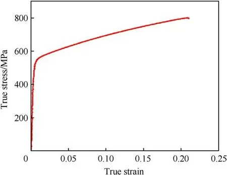
Fig.5.True stress-true strain curve for stainless steel 316 L [50].
Previous research has demonstrated that lateral corrugation can enhance energy absorption, and that tapered tubes can decrease the initial PCF.This study therefore proposes the lateral corrugated tapered tube and its sandwich structure,which combines these two benefits.Here,3D printing technology was utilized to create metal corrugated tubes.The energy absorption performance of the corrugated tapered tubes and their corresponding sandwiches was investigated by finite element simulation and experiment.Furthermore,the oblique compression resistance of the corrugated tapered tubes was analyzed numerically and compared with the corresponding straight tube.The effect of corrugation parameters on the deformation pattern as well as energy absorption was also investigated.
2.Experiments
2.1.Structural configurations
In this study, the corrugated tubes are created by introducing corrugations on the cross-section of the conical tube (CT).Corrugated tubes are divided into single corrugated tapered tube (ST)and double corrugated tapered tube(DT)according to the number of corrugated walls, and the DT is formed by crossing two ST, as shown in Fig.1.In addition,three types of sandwich structures with thin-walled tubes as the core layer are proposed: conical tube sandwich (CTS), single corrugated tapered tube sandwich (STS),and double corrugated tapered tube sandwich (DTS), as shown in Fig.1.The mathematical model and geometric parameters of the ST are shown in Table 1 and Fig.2,respectively.In addition,the radius of the bottom surface of the CT is the same as the reference radius of the ST,i.e.,R0in Fig.2,and the inclination angle θ is the same as that of the ST.The thickness of all three thin-walled tubes is 0.44 mm.All thin-walled tubes in the experiment were made by 3D printing technology.The additive manufacturing equipment DiMetal-280 produced by Laseradd was used to manufacture thin-walled tubes.The working principle of the equipment was to sinter 316 L stainless steel powder using selective laser melting (SLM) technology.The sandwich structure includes two circular panels and a core structure, which is composed of five thin-walled tubes arranged in a cross shape(see Fig.1(b)).In order to keep the core layer from splitting away from the panel, five circular grooves with a depth of 1.2 mm and a width of 5 mm were carved on the panel.As shown in Fig.1(b),The edges of the core were put into the groove,and then epoxy glue was used to bond the core layer and the panel together to form a sandwich structure.
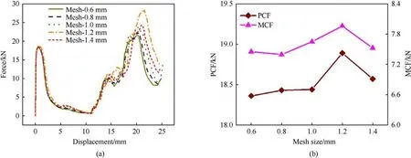
Fig.6.Mesh convergence analysis: (a) Force-displacement curves; (b) MCF and PCF.
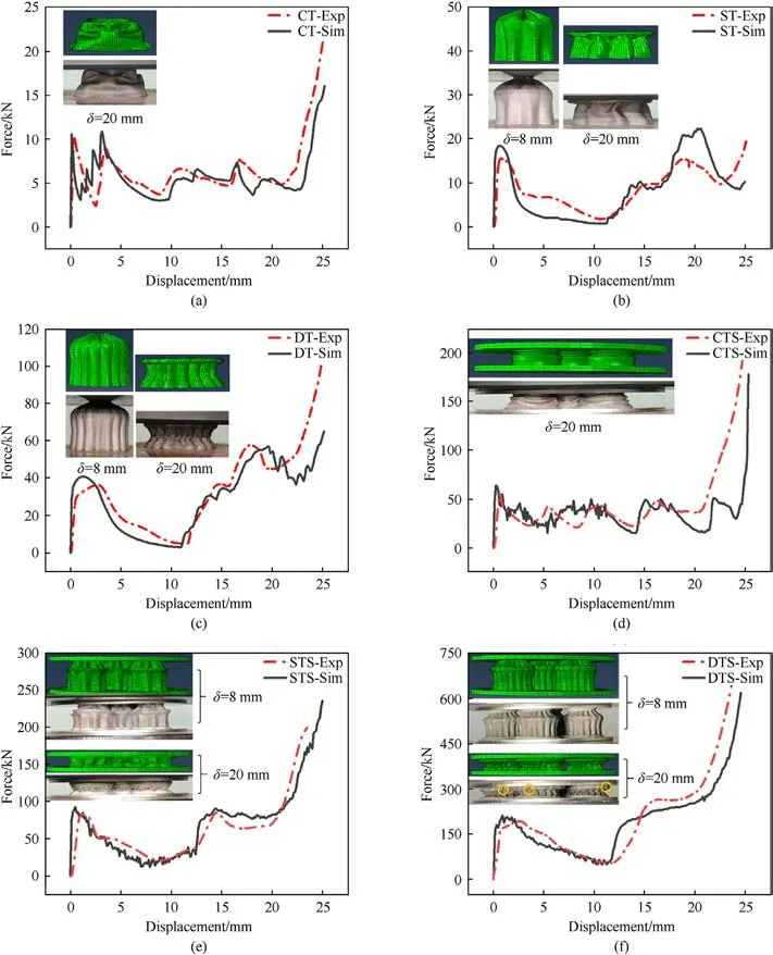
Fig.7.Deformation modes and force-displacement curves: (a) CT; (b) ST; (c) DT; (d) CTS; (e) STS; (f) DTS.

Table 2 Energy absorption evaluation indicators of the models.
2.2.Quasi-static compression test
Quasi-static compression experiment is a common method for measuring the energy absorption performance of structures.A computer-controlled universal testing machine was used to perform compression tests.Fig.3 shows the upper and lower platen and the specimen to be tested.The specimen was compressed uniformly at a rate of 0.05 mm/s,as shown in Fig.3.The force and displacement data during the experiment were also recorded and transmitted to the computer by the sensors on the test machine.
3.Finite element validation
The finite element analysis software Abaqus/Explicit was used to model the quasi-static compression of thin-walled tubes and sandwich structures.In the compression model of the thin-walled tube, the 4-node shell element (S4R) with mesh size 0.8 mm was used to simulate thin-walled tubes.The complex interactions between different components were calculated using a general contact setting with a penalty algorithm, and the friction coefficient was set to 0.2 [33,34,49], as shown in Fig.4.During the loading process, the lower loading panel was fixed, and the upper loading panel was set to move downward at a speed of 0.5 m/s.Both the lower and upper loading panels were set as rigid bodies.In the compression model of the sandwich structure, the panels were modeled by 8-node solid elements (C3D8R).The contact between the panels and the core layer was set to the Tie connection,and the complex interactions between different components were calculated using a general contact setting with a penalty algorithm.The material is 316 L stainless steel with a density of 7850 kg/m3, an elastic modulus of 185 GPa,and Poisson’s ratio of 0.3,which is the same as our previous research [50].The true stress-true strain curve produced from the standard tensile test, as shown in Fig.5[50].The 316 L stainless steel was used with the standard isotropic hardening elastic-plastic constitutive model, and the material parameters of the plastic section were obtained from Fig.5.
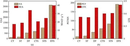
Fig.8.Energy absorption parameters: (a) SEA and EA; (b) CFE and PCF.
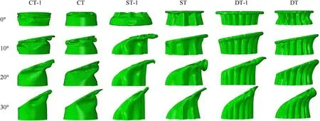
Fig.9.The deformation of structures at the crushing displacement of 20 mm.
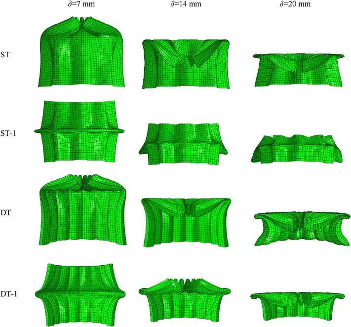
Fig.10.Deformation processes of ST, ST-1, DT and DT-1 under axial loading.
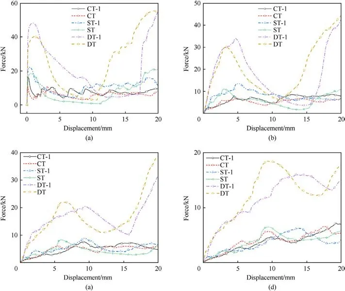
Fig.11.Force - displacement curves under different loading angles: (a) 0°; (b) 10°; (c) 20°; (d) 30°.
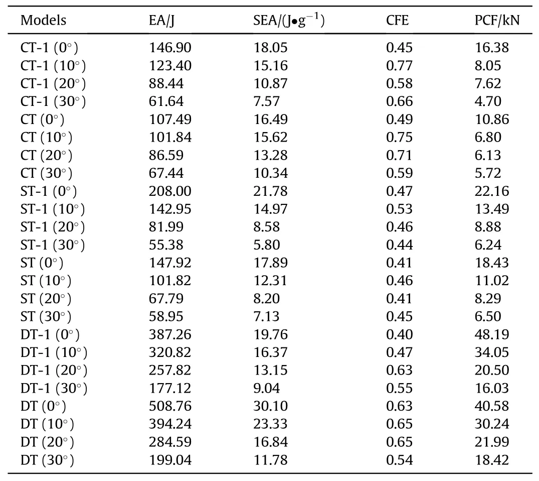
Table 3 Energy absorption characteristics under different loading angles.

Table 4 Energy absorption characteristics of DTSs with different geometric parameters.
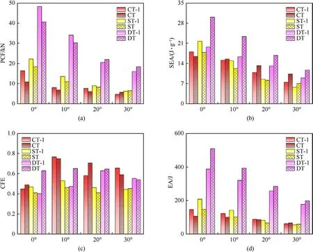
Fig.12.Energy absorption parameters under different loading angles: (a) PCF; (b) SEA; (c) CFE; (d) EA.
To compare the crashworthiness of different structures, researchers have proposed some evaluation indicators, such as EA,SEA, PCF, MCF, and CFE.
EA represents energy absorption.Where l and F represent the crushing distance and crushing force,respectively.In this study,l is set to be 20 mm.
where,m is the mass of the structure.SEA can be used to compare the energy absorption per unit mass.
MCF indicates the mean crushing force during the entire compression process.
PCF represents the peak crushing force.In general, during the compression process, it is desired to obtain a smaller PCF.
CFE reflects the energy absorption efficiency of the structure and it is the ratio of the MCF and PCF, as follows,
Mesh convergence analysis is a critical step in verifying model reliability.In this article,the mesh sizes were set to 1.4 mm,1.2 mm,1.0 mm,1.8 mm, and 0.6 mm, respectively, and the simulation results of the ST at different mesh sizes are presented in Fig.6.From Fig.6(a), it can be observed that the simulation results are very close when the mesh size is less than 1 mm.In addition,when the grid size is less than 0.8 mm,MCF and PCF tend to converge and the variation amplitude is less than 2% (Fig.6(b)).Therefore, considering the computational efficiency, the mesh size is set to 0.8 mm for the finite element analysis (FEA).
4.Discussion
4.1.Deformation modes
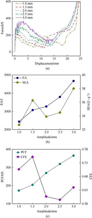
Fig.13.Mechanical properties of DTSs with different amplitudes: (a) Forcedisplacement curves; (b) SEA and EA; (c) CFE and PCF.
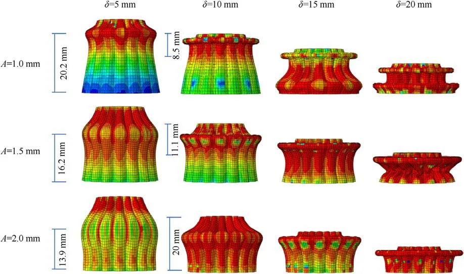
Fig.14.Deformation process of the core layer of DTSs with different amplitudes.
The deformation pattern of the structure,which is controlled by numerous factors including structural dimensions, cross-sectional shape, and wall thickness [3,11,30], and is critical to the structure’s ability to absorb energy.In this paper, a great change in the deformation pattern of the tube is also found when corrugations are introduced.The quasi-static compression test results of the three thin-walled tubes and the sandwich structures are shown in Fig.7.The CT showed a diamond-shaped progressive folding deformation mode(presented in Fig.7(a)),and the CTS had a ringshaped progressive folding deformation mode (presented in Fig.7(d)).The corrugated tubes first started to fold in the middle region to form a plastic hinge, and with the increase in deformation, secondary folding occurred near the bottom region.The top edges of the ST and DT collapse to the middle at the initial stage of deformation, while those of the tubes in the STS and DTS are always attached to the panel during the whole compression test.At the region where the plastic hinge is formed,the corrugated tube wall expands outward and the corrugation is flattened,which will increase the energy absorption of the corrugated tube.The number of folds in the corrugated tube is much less than that of the circular tube.Each peak of the force-displacement curve corresponds to a folding deformation;therefore,the number of peaks of the force-displacement curve of the corrugated tube is less than that of the circular tube.As shown in Fig.7(f), the plastic hinge region of the DTS starts to crack at a displacement of 16 mm due to excessive lateral expansion,but the crack appears in the later stage of the deformation and has less effect on the entire energy absorption, and the experimental and simulated results are in good agreement, so the effect of fracture is not considered in FEA.The errors in Fig.7(b) are mainly caused by the thickness nonuniformity of 3D printing.Although we have designed that the total mass of the experiment and simulation were the same, the thickness non-uniformity of the actual fabricated tube was inevitable.Moreover,since the thickness of the tube was only 0.43 mm,the error caused by thickness non-uniformity was also significant.During the compression process, the collapse would occur in the thinnest places,so the peak force from the experiment was slightly lower than that from the simulation.The top and bottom of the circular tube of CTS were bonded to the panel by epoxy glue(Fig.7(d)),which reduced the effective height of the tube’s vertical folding.In addition, the axial deformation of the circular tube is closely related to the height, so the experimental curve enters the densification earlier and the number of waves is one less,as shown in Fig.7(d).
Similar to the response of most thin-walled structures in axial compression, the corrugated tube experiences three deformation phases:elastic phase,plastic phase,and densification phase,as can be seen in Fig.7.The compression forces of the corrugated tube and its corresponding sandwich structure decrease rapidly after reaching the initial PCF and then increase rapidly when the secondary folding occurs (presented in Fig.7(e) and 7(f)), while the fluctuation of the circular tube and its sandwich structure is relatively smaller(see Fig.7(d)).In addition,due to the reinforcement of the tube wall, the elastic deformation of the corrugated tube becomes more difficult,so the initial PCF is greater than that of the circular tube.From the results of deformation and force displacement curves,there is good agreement between the experiment and the simulation, which also verifies the reliability of the numerical model.
4.2.Energy absorption performance
Table 2 and Fig.8 show the energy absorption evaluation indicators for different structures.It can be seen from Fig.8,both the STS and DTS have higher EA and SEA than those of the CTS,but are also accompanied by a higher PCF.The same phenomenon is observed in the individual thin-walled tubes.This is because the tube’s ability to resist deformation was greatly enhanced by the corrugated design and thus improved energy absorption capability,especially in the case of double corrugated tubes.It can be calculated from Table 2 that compared with CT, the SEA, EA, and CFE of DT are increased by 95.7%, 373%, and 31.6%, respectively.This improvement in energy absorption performance was also presented in the sandwich structures.Therefore, enhancing energy absorption by introducing lateral corrugation is a useful method to increase the crashworthiness of energy absorbers.
5.Energy absorption performance under oblique loads

Fig.15.Mechanical properties of DTSs with different corrugation numbers: (a) Forcedisplacement curves; (b) SEA and EA; (c) CFE and PCF.
In practice,energy absorbers are also subjected to oblique loads during collisions.So, the oblique crashworthiness of Structures must be investigated.From previous studies, tapered tubes have more advantages in reducing the initial PCF and resisting oblique loads.Therefore, the deformation pattern and energy absorption performance of lateral corrugated tapered tubes were investigated under quasi-static oblique loads in this section, and compared it with the corresponding straight tube.The round straight tube(CT-1), single corrugated straight tube (ST-1) and double corrugated straight tube(DT-1)were studied.The compression performance of the tubes under four loading angles (0°, 10°, 20°and 30°) were investigated by FEA, as show in Fig.9.
Fig.9 shows the deformation of structures at a displacement of 20 mm under the axial loading (0°) and oblique loading (30°, 20°,and 10°).The deformation profiles of ST, ST-1, DT and DT-1 during axial loading are shown in Fig.10.The deformation modes of each tube are different and change with the loading angle.When subjected to axial loading, the CT showed a diamond-shaped folding deformation mode, while the CT-1 showed a ring-shaped folding deformation mode(Fig.9).As shown in Fig.10,the upper part of the ST collapsed to the middle and then the lower part folded again,while ST-1 formed a plastic hinge in the middle and then the middle region flipped down,and the upper part did not collapse to the middle.Both DT and DT-1 collapsed to the middle at the initial stage to form plastic hinges.But the difference is that after DT-1 forms a plastic hinge, the middle part expands continuously,while DT will fold again in the lower part to form a second plastic hinge, which is reason that the energy absorption of DT is much greater than that of DT-1.
Under oblique loading, the deformation mode of each tube changed from plastic folding to overall bending when the loading angle increases,as shown in Fig.9.Especially for the tubes without corrugations(CT and CT-1),the number of plastic folding decreased sharply.The change of deformation pattern led to the change of the force-displacement curves.It can be seen from Fig.11, with the increase of the loading angle, the curve for each tube becomes smoother,in which the fluctuation amplitude decreases.Compared with the other tubes, the deformation of the DT was more stable under various loading angles.As the loading angle increases, the position of the PCF is more backward along the displacement axis(see Fig.11).It is because that under axial loading, the plastic deformation existed in the full cross-section at the beginning;while under the oblique loading, the contact area and the plastic deformation zone are both small at the beginning.
The energy absorption characteristics for oblique loads are shown in Table 3, and the PCF, EA, CFE, and SEA are plotted in Fig.12.With the increase of the loading angle,the PCF,EA,and SEA all decreased,because the deformation mode of each tube changed from plastic folding to overall bending and the resistance to deformation was weakened.As shown in Fig.12(c),it is found that at the loading angle 10°, other tubes except DT-1 have the largest CFE.
At loading angles 0°and 10°,the PCF of the three tapered tubes(CT,ST and DT)is smaller than those of the corresponding straight tubes (CT-1, ST-1 and DT-1), as shown in Fig.12(a).As the loading angle increases, the EA and SEA of CT and ST are larger than their corresponding straight tubes, as in Fig.12 (b) and 12(d).The crashworthiness of DT is much better than DT-1 at any loading angle.It can be seen from Table 3, the EA, SEA, and CFE of DT are 28.6%, 48.9%, and 55% higher than DT-1 under axial loading,respectively, while PCF is reduced by 16.5%.Furthermore, DT has the largest EA and SEA at any loading angles.In summary, the tapered design offers a bigger benefit in reducing the initial PCF at small loading angles and resisting the oblique load compared with the corresponding straight tube, and DT has the best energy absorption performance under oblique load.
6.Parameter analysis
The quasi-static compression test results have shown that DTS has better energy absorption among all structures; therefore, to further improve its crashworthiness, a parametric analysis of the DTS was performed.In this section,the effects of thickness,number of corrugations,base radius,amplitude and inclination angle on the crashworthiness of DTSs were investigated.The energy absorption characteristics of DTSs with different geometric parameters are shown in Table 4.
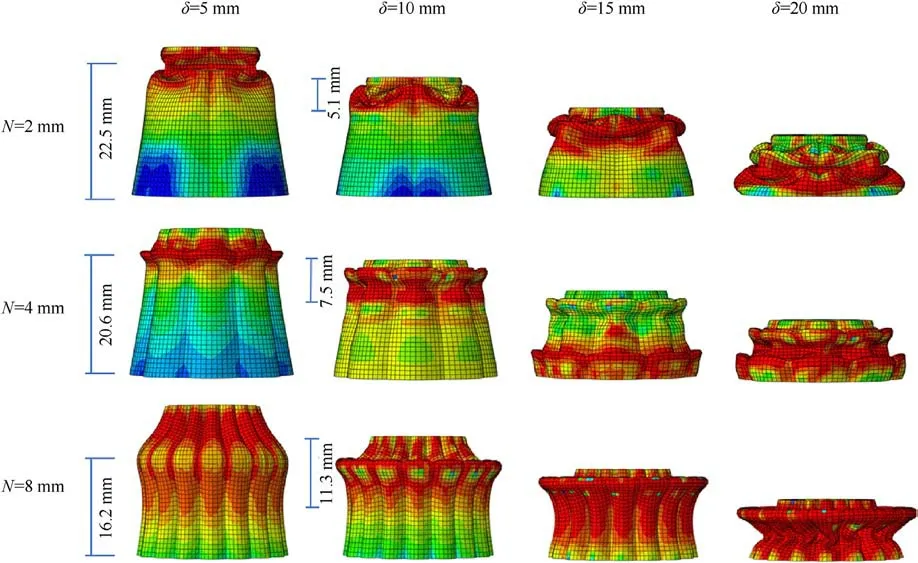
Fig.16.Deformation process of the core layer for DTSs with different corrugation numbers.
6.1.The effect of the amplitude
Previous studies [10,12] have shown that the structure’s crashworthiness is greatly affected by the amplitude, and this phenomenon was verified in this study.The mechanical properties of the DTSs with different amplitudes are shown in Fig.13.Since the deformation of DTSs with amplitudes of 2.0 mm, 2.5 mm and 3.0 mm are similar, only the deformation patterns of DTSs with amplitudes of 1.0 mm,1.5 mm and 2.0 mm are compared.To see the deformation details more clearly,only one tube of the core layer is shown, as presented in Fig.14.When the loading displacement is 5 mm, the heights of the plastic hinges of the core tube are 20.2 mm,16.2 mm,and 13.9 mm,respectively,as shown in Fig.14.This indicates that when the amplitude is smaller, the position of the plastic hinge is closer to the loading end.When the loading displacement is 15 mm,the first plastic hinge of the core tube with an amplitude of 1 mm has been fully folded and a second plastic fold has occurred.This indicates that as the amplitude decreases,the number of plastic hinges increases, and the plastic folding is completed earlier and more thoroughly.This is also verified in the force-displacement curve.As shown in Fig.13(a), the DTS with an amplitude of 1.0 mm has one more peak than other DTS, and the force of the DTS with 1.0 mm amplitude drops earlier after the initial PCF.
When the loading displacement is 10 mm,for the core tube with three amplitudes, large plastic deformation is generated with a length of 8.5 mm, 11.1 mm and 20 mm near the plastic hinge,respectively (see Fig.14).This indicates that the resistance of the tube wall to deformation is larger with increasing amplitude because more plastic deformations are occurring in the area adjacent to the plastic fold,as shown in Fig.14.It also can be seen from Fig.13(a) that the force increases with the increase in amplitude,and EA and PCF also increase linearly with the increase in amplitude (see Fig.13(b) and 13(c)).However, the mass of the structure increases with the increase in the amplitude.Therefore, SEA does not increase gradually like EA, but gets a larger value when the amplitude is 1.5 mm.The DTS with an amplitude of 1.5 mm has the largest CFE and is 26.4%higher than the DTS with an amplitude of 2.5.In summary, selecting appropriate amplitude can not only obtain higher SEA and CFE, but also reduce PCF.
6.2.The effect of the corrugation numbers
The corrugation number is another key parameter that affects the crashworthiness of DTS.The Mechanical properties of the DTSs with different corrugation numbers are shown in Fig.15.Since the deformation of DTSs with corrugation numbers of 6,8,10 and 12 is similar, only the deformation patterns of DTSs with corrugation numbers of 2,4,and 8 are compared(Fig.16).As can be seen from Fig.16 that the deformation pattern of the structure changes with the number of corrugations.The deformation modes of DTS with corrugation numbers of 2,4 and 8 are diamond-shaped progressive folding,ring-shaped progressive folding,and lateral expansion and contraction, respectively.More axial plastic folding deformation is observed in DTS with corrugation numbers of 2 and 4,which is why more wave peaks appear in their load displacement curves (see Fig.15(a)).When the loading displacement is 5 mm,the heights of the plastic hinges of the core tube are 22.5 mm, 20.6 mm, and 16.2 mm, respectively, as shown in Fig.16.When the loading displacement is 10 mm,large plastic deformation is generated with a length of 5.1 mm, 7.5 mm and 11.3 mm near the plastic hinge,respectively(see Fig.16).So, similar to the effect of amplitude,the plastic hinge is formed more easily, and the position of the plastic hinge is closer to the loading end with a decrease in the number of corrugations.
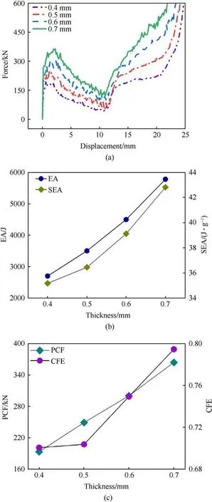
Fig.17.Mechanical properties of DTSs with different thicknesses: (a) Forcedisplacement curves; (b) SEA and EA; (c) CFE and PCF.
The energy absorption performance of the DTS is greatly affected by the corrugation numbers, as shown in Fig.15(b) and 15(c).PCF increases linearly with the number of corrugations.With the increase of corrugation numbers, EA, SEA and CFE all increase first,then decrease,and then increase again.DTS with corrugation numbers of 6 and 8 have good energy absorption performance.The EA and SEA of the DTS with corrugation numbers of 8 improved 111.2% and 66.5%, respectively, compared with the DTS with corrugation numbers of 2.Therefore, the appropriate number of corrugations is crucial to the crashworthiness of the structure.
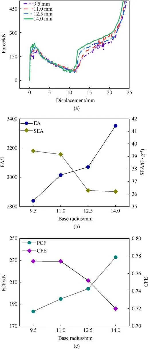
Fig.18.Mechanical properties of DTSs with different Base radius: (a) Forcedisplacement curves; (b) SEA and EA; (c) CFE and PCF.
6.3.The effect of the thickness
Fig.17 shows the energy absorption parameters and forcedisplacement curves of DTS with different wall thicknesses.As shown in Fig.17(a), the force increases as the wall thickness increases, and the force-displacement curves of the DTSs with different wall thicknesses have the same trend.The SEA, EA, and PCF increase linearly with the increase in wall thickness, and DTS with a wall thickness of 0.7 mm achieves the largest CFE(Fig.17(b)and 17(c)).It shows that increasing the wall thickness could increase the energy absorption of the structure in some way, but it will face the problem of a large increase in the initial PCF.
6.4.The effect of the base radius
To study the influence of base radius on sandwich structure,the quasi-static compression of DTS with a base radius of 9.5 mm,11 mm,12.5 mm,and 14 mm was simulated,respectively,as shown in Fig.18.The base radius has little effect on the energy absorption of the structure,and the variation range of each evaluation index is small.The PCF and EA increase with the increase in the base radius,because the cross-section of the tube increases.Although the EA is increasing,the mass of the structure is increasing more,resulting in the SEA decreasing instead.
6.5.The effect of the inclination angle
The Mechanical properties of the DTSs under loadings with different inclination angles are shown in Fig.19.The tapered design significantly reduces the PCF, and there is a negative correlation between the loading angle and PCF,as shown in Fig.19(c).The PCF of the DTS with an inclination of 15°decreases by 29.3%compared to an inclination of 0°.In addition, a reasonable inclination angle can also achieve greater SEA and CFE.The CFE of the DTS with an inclination of 15°is 0.808, which is 18.1% higher than that of the straight tube design,and the SEA also reaches 38.65 J/g,as shown in Table 4.Therefore, the tapered design of this structure is more crashworthy.
For a more visual comparison of the effects of each parameter,radar charts with the same scales are plotted as shown in Fig.20.It can be seen from Fig.20 that the amplitude and thickness have significant effects on the PCF and are positively correlated.The SEA is influenced by the corrugation number greatly and the inclination angle has a significant effect on CFE.The reference radius has the smallest effect on all evaluation indicators.
7.Conclusions
In this paper, single and double corrugated tapered tubes and their sandwich structures are designed and manufactured using 3D additive technology.Their energy absorption and deformation were studied under axial compression loading through experiments and FE simulations.In addition, the crashworthiness of thin-walled tubes under oblique loading was investigated.Finally, parametric analyses of the DTSs were carried out.The main conclusions are as follows.
(1) Introducing lateral corrugations improve the tube’s energy absorption but also increase the initial PCF.Compared with the CT, the SEA and EA of the ST are increased by 9.1% and 38.2%, respectively.
(2) The EA and SEA of the DTS are improved by 369%and 93.8%,respectively, compared with the CTS.
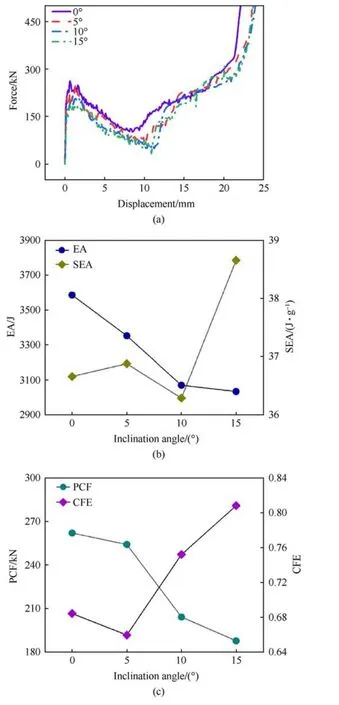
Fig.19.Mechanical properties of DTSs with different inclination angle: (a) Forcedisplacement curves; (b) SEA and EA; (c) CFE and PCF.
(3) Compared with straight tubes, conical tubes significantly reduce the initial PCF under axial loads and can better resist oblique loads.For example,compared to its straight tube,the PCF of ST is reduced by 16.8%at axial loading and the SEA of ST is improved by 22.9% at 30°loading.

Fig.20.The effects of each parameter: (a) Amplitude; (b) Corrugation number; (c) Thickness; (d) Base radius; (e) Inclination angle.
(4) The deformation mode of the DTS is greatly affected by the amplitude and corrugation numbers.Axial folding decreases with the increase of amplitude and corrugation numbers.
(5) The energy absorption performance of DTS is found to be greatly related to the amplitude, corrugation numbers, and thickness.Lower PCF,higher EA and SEA will be obtained by choosing the appropriate corrugation numbers and amplitude.Compared to the DTS with a corrugation number of 10,the EA and SEA of the DTS with a corrugation number of 8 increased by 17.4% and 29.6%, respectively, and the PCF decreased by 9.2%.
Declaration of competing interest
The authors declare that they have no known competing financial interests or personal relationships that could have appeared to influence the work reported in this paper.
Acknowledgements
The first author would like to thank the grants from the National Natural Science Foundation of China (Nos.52078152 and 12002095), and Guangzhou Government-University Union Fund(No.202201020532).
- Defence Technology的其它文章
- Explosion resistance performance of reinforced concrete box girder coated with polyurea: Model test and numerical simulation
- An improved initial rotor position estimation method using highfrequency pulsating voltage injection for PMSM
- Target acquisition performance in the presence of JPEG image compression
- Study of relationship between motion of mechanisms in gas operated weapon and its shock absorber
- Data-driven modeling on anisotropic mechanical behavior of brain tissue with internal pressure
- The effect of reactive plasticizer on viscoelastic and mechanical properties of solid rocket propellants based on different types of HTPB resin

