Underdetermined direction of arrival estimation with nonuniform linear motion sampling based on a small unmanned aerial vehicle platform
Xinwei Wang, Xiaopeng Yan, Tai An, Qile Chen, Dingkun Huang
Science and Technology on Electromechanical Dynamic Control Laboratory, School of Mechatronical Engineering, Beijing Institute of Technology, Beijing 100081, China
Keywords:Unmanned aerial vehicle (UAV)Uniform linear array (ULA)Direction of arrival (DOA)Difference co-array Nonuniform linear motion sampling method
ABSTRACT Uniform linear array (ULA) radars are widely used in the collision-avoidance radar systems of small unmanned aerial vehicles (UAVs).In practice, a ULA’s multi-target direction of arrival (DOA) estimation performance suffers from significant performance degradation owing to the limited number of physical elements.To improve the underdetermined DOA estimation performance of a ULA radar mounted on a small UAV platform,we propose a nonuniform linear motion sampling underdetermined DOA estimation method.Using the motion of the UAV platform, the echo signal is sampled at different positions.Then,according to the concept of difference co-array, a virtual ULA with multiple array elements and a large aperture is synthesized to increase the degrees of freedom (DOFs).Through position analysis of the original and motion arrays,we propose a nonuniform linear motion sampling method based on ULA for determining the optimal DOFs.Under the condition of no increase in the aperture of the physical array,the proposed method obtains a high DOF with fewer sampling runs and greatly improves the underdetermined DOA estimation performance of ULA.The results of numerical simulations conducted herein verify the superior performance of the proposed method.
1.Introduction
When a UAV flies at low altitudes, the radar of the collision avoidance system must be able to accurately identify target obstacles in the environment.In recent years,the wide application of direction of arrival (DOA) estimation technology based on array antennas [1-3] has improved the azimuth resolution ability of UAVs for the targeting perspective.Uniform linear array(ULA)is the most common array structure,and ULA-based DOA estimation is an important component of array signal processing [4-6].The commonly used methods for DOA estimation include the beamforming and subspace algorithms.The beamforming algorithms include conventional beamforming (CBF) [7] and minimum variance distortion-less response(MVDR)[8].The subspace algorithms include the multiple signal classification algorithm (MUSIC) [9],and the rotation invariance technique (ESPRIT) [10].The above algorithms use a ULA composed of M elements to identify M-1 incoherent signals.The size of most mainstream small UAVs is several tens of centimeters, and their load-carrying capacities and space availability are extremely limited.For example, among commercially available UAVs, the dimensions of the DJI Mavic 3 small UAV from DJI in China and ANAFI Ai small UAV from Parrot in France 221 mm×96.3 mm×90.3 mm (length×width×height) and 304 mm ×130 mm×118 mm, respectively.Large-aperture array antennas or active phased array antennas place high requirements on UAVs in terms of load and space,which makes them unsuitable for use with small UAVs.When UAVs are operated in complex environments such as urban areas, the number of targets to be measured far exceeds the number of physical array elements.In such underdetermined environments, it is difficult to perform high-resolution DOA estimation owing to the limited aperture of UAVs, which affects their ability to accurately detect target obstacles.
To realize underdetermined DOA estimation, several scholars have proposed diverse sparse array structures based on the concept of difference co-array, such as the minimum redundancy array(MRA) [11,12], nested array (NA) [13-18], super nested array[19,20],coprime array(CA)[21,22],generalized coprime array[23],and sparse coprime array [24].With the same number of physical sensors, a sparse array can achieve higher degrees of freedom(DOFs) and superior DOA estimation performance compared to a ULA.The above-referenced methods generate sparse arrays by varying the distance between physical elements on a stationary platform.Recently,for moving platforms,a few scholars have used the synthetic aperture technology and the difference co-array concept to construct virtual ULAs with larger apertures.The holes in a CA are filled through array motion to generate a hole-free difference co-array [25-27].By increasing the interval between physical elements in the array and combining the original array and moving array, the DOFs of the original array can be improved exponentially[28-31].The above methods[11-31]require that the array physical elements be sparsely spaced from each other,that is,the spacing of array physical elements should exceed half wavelength.This requirement increases the platform space needed for array antennas, as well as the sensitivity of array antennas to amplitude-phase error, leading to severe deviations in DOA estimation [32,33].
High-resolution DOA estimation based on a ULA mounted on a moving platform is mostly performed in passive sonar detection,and the representative method is extended towed array measurement (ETAM) [34].By using platform motion, the signal is uniformly sampled at equal intervals, and the array aperture is expanded through phase correction of two adjacent signal segments.However, this method requires overlapping correlation processing of sensors.In other words, for two adjacent sampling moments,the array should be able to satisfy the position overlap of several sensors,which limits the efficiency of aperture expansion.
There are also relevant applications in the field of automotive radar.In Ref.[35], a high-resolution DOA approach is proposed by utilizing the relative motion between radar and targets,and a very large virtual aperture can be created by combining the signal vectors from multiple consecutive coherent processing intervals(CPIs).However, the sampling interval of this method is uniform in airspace, so its aperture improvement is limited.
Therefore, in this study, based on moving UAV platforms, we propose a DOA estimation method for nonuniform linear motion sampling in underdetermined environments.The ULA is used as the receiving array, and the target echo is sampled at several specific positions by UAV platforms moving uniformly along the array direction.The original ULA and the multiple moving ULAs are synthesized into a multi-element, large-aperture, virtual ULA by using the concept of difference co-array[36]to obtain a higher DOF.By analyzing the position relationship between the moving array and the original array, the optimal nonuniform motion sampling scheme for ULAs is realized.
The major contribution of this paper is two-fold: (i) We derive the echo signal model of moving array,and express the echo signal at different times as vector through phase compensation.Through vectorization and de-redundancy of covariance matrix, the received data matrix in the form of difference co-array is obtained.It is shown that the accuracy of DOA estimation and the number of distinguishable objects are determined by the continuous and uniform spatial guidance vector in the received data matrix.(ii)We derive closed-form expressions for the number of both DOFs and the holes in the difference co-array, under array motion for ULA,and propose a nonuniform linear motion sampling method based on the optimal two-level NA.
The remainder of this paper is organized as follows: Section 2 describes the motion array signal model and DOA estimation method.In Section 3, the nonuniform linear motion sampling method is introduced.The simulation results are presented in Section 4.Finally, a few concluding remarks are presented in Section 5.
2.Signal model and DOA estimation method
2.1.Motion array signal model
The antenna shown in Fig.1 is composed of a transmitting array element and M linear receiving array elements with spacing d that move linearly and uniformly with velocity v along the array arrangement direction.
At time t, the signal transmitted by the radar is expressed as follows:
where u(t)is a slow-varying amplitude-modulation function,φ(t)is a slow-varying phase-modulation function,f0=c/λ is the carrier frequency,c is the speed of light,and λ is the wavelength of signal.
If the far-field narrowband condition is satisfied and array element 0 is taken as the reference,the echo signal of the mth array element at time t can be expressed as follows:
In Eq.(2), τk= (Rs+Rmk-˜vkt ) /c is the echo delay of the kth target;˜vkis the relative speed between the platform and the target;φ(t )is the phase-modulation function of kth target echo;and R=Rs+Rkis the round-trip distance of the signal, where Rsis the distance between the transmitting array element and the target,and Rmkis the distance between the mth receiving array element and the target k.Let the distance between the target and array 0 be denoted by R0k.Thus,we have Rmk=R0k-md sin(θk),where d=λ/2 is the physical array element spacing.Let v be the speed of platform movement;then,we have ˜vk=v sin θk.Therefore,Eq.(2)can be expressed as follows:
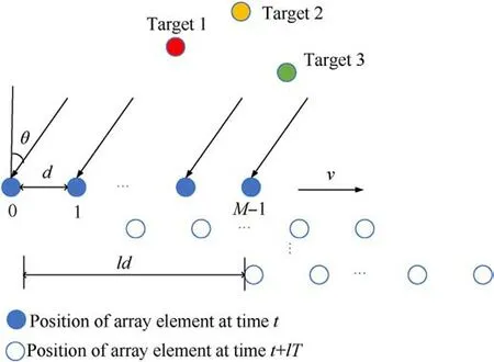
Fig.1.Motion array model.
where exp(jφk) =exp( -j2π(Rs+R0k) /λ),φkis the phase term independent of angle.
By combining Eq.(3) with the local oscillator signal, we can express the beat frequency signal as follows:
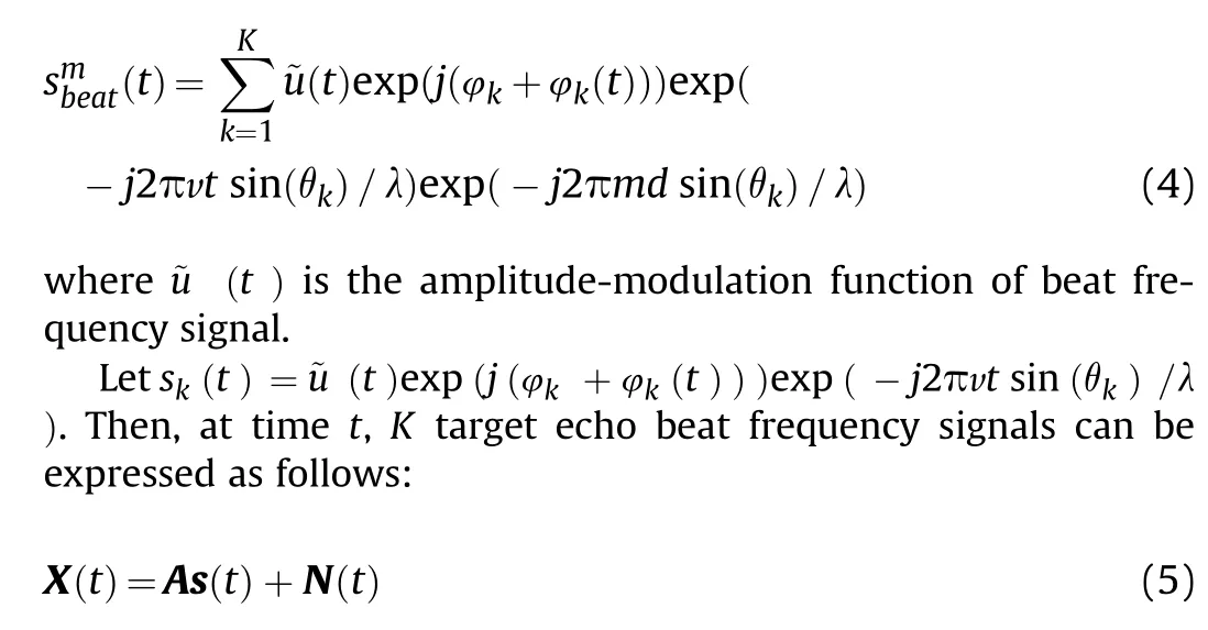
where A = [a (θ1)a (θ1) …a (θk) ] represents the array manifold matrix,a(θk)=[1 exp(-j2πd sin θk/λ)exp(-j2π ·2d sin θk/λ)…exp(-j2π(M-1)d sin θk/λ)]Trepresents the spatial steering vector, s (t ) = [s1(t )°s2(t ) · · ·°sk(t ) ]T, T is the transpose symbol, and N (t ) is the complex Gaussian white noise vector.
We set the time interval T and let vT =d.Then,we consider that the target echoes remain unchanged with respect to the array direction.Accordingly, at time t + lnT, the target echoes can be expressed as follows:
where lnbelongs to the set G = {l1l2…lN}, and the set G is an N-element set of integers with increasing magnitudes.When the incoherent far-field narrowband signal condition is satisfied, we have u(t +lnT -τk)≈u(t -τk)and φk(t +lnT )≈φk(t ).Thus,the following equation can be obtained:
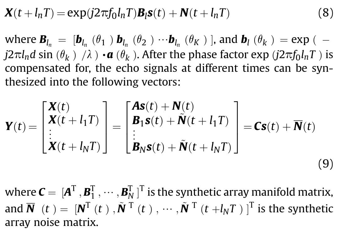
Based on Eqs.(5)-(7), at time t + lnT, K target echo beat frequency signals can be expressed as follows:

Table 1 Positions of MRA elements for different element counts.
2.2.DOA estimation method
As shown in Eq.(9), a sparse array is synthesized owing to nonuniform sampling of the linear motion array.
First,the sparse array signal model is spatially smoothed.Then,the DOA is estimated by using beamforming or subspace algorithms.
The covariance matrix of Y (t ) is as follows:
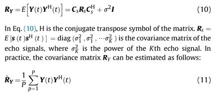

Table 2 Array setting for DOF maximization.

Table 3 Maximum DOFs obtained using the optimal two-level NA sampling scheme.

Table 4 Computational complexity analysis.

where M ×N represents the number of array elements in the synthesized array after nonuniform motion sampling, xiand xj,respectively,represent the position vectors of the ith and jth array elements in the array.
According to Eq.(13), the matrix Z is redundant when the set contains repeated elements.After removing the redundancies, ˜Z is obtained,which can be considered the received data matrix of the difference co-array.Consider a long, continuous, uniform part of the steering vector in ˜Z , which is equivalent to obtaining a continuous virtual ULA.To recover the full-rank characteristics of the virtual signal covariance matrix,a spatial smoothing algorithm[37]is used to construct a new signal covariance matrix.Then,DOA estimation is performed using the beamforming or subspace algorithms.In sum, a reasonable nonuniform motion sampling scheme that can extend the continuous virtual ULA in the synthetic array to the extent possible is crucial for improving the accuracy of DOA estimation and increasing the number of resolvable targets.
3.Nonuniform linear motion sampling method
3.1.Method design
For a ULA with M physical elements, the position of each element can be expressed as follows:

where lnbelongs to the set G = {l1l2…lN},and different sets G can form different synthetic virtual arrays.The synthetic virtual array is represented as follows:
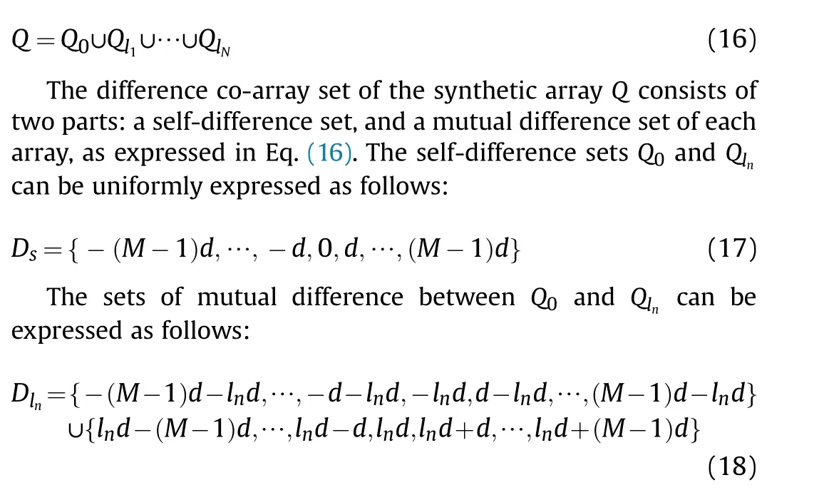
The sets of mutual difference between different Qlncan be expressed as follows:
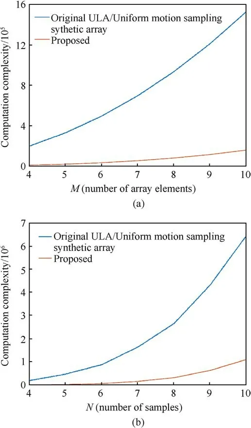
Fig.2.(a) Relationship between computational complexity and number of physical elements; (b) Relationship between computational complexity and number of sampling runs.
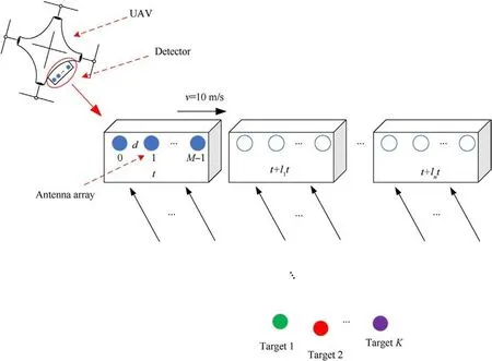
Fig.3.Schematic diagram of simulation scene.

Table 5 Simulation parameters.
where n ,i ,j = 0,1 , … ,N, i ≠j.
According to Eqs.17-19, the sets of difference co-arrays in the synthetic array Q can be expressed as follows:

where l0=0,and to reduce the redundancy of the synthetic array,l should be greater than M.From Eq.(21), the repeated elements in l0, ln, and li-ljare removed to generate a set ˜G composed of ˜N elements:
If ˜DQdenotes a difference co-array with a free-hole, the two adjacent elements lnand ln+1 in ˜G must satisfy the expression˜ln+M ≥˜l n +1 - (M -1),that is,˜l n +1 -˜l n ≤2M -1.Therefore,when˜ln+1 -˜ln>2M -1,holes appear in the difference co-array ˜DQ.When ˜ln+1 -˜ln= 2M - 1, the hole-free ˜DQhas the least redundancy,and the set ˜G in this case is a ULA with interval 2M -1.

Fig.4.Weight functions of synthetic difference co-arrays for different a: (a) a = 1; (b) a = 14; (c) a = 7; (d) a = 8.
An analysis of the ULA ˜G reveals that ˜G can be obtained from the difference between the set {l0=0 } and the set of motion sampling positions G = {l1l2…lN}, and it is expressed as follows:
where li,lj∈Gs= {0 ,l1,l2, … ,lN}.Therefore, the set Gsis the optimal nonuniform sampling scheme under the condition that the difference co-array of the synthetic array is non-porous, and the redundancy is minimal.
There are several arrays with the property of Gs, among which the most common ones are the minimum redundancy array(MRA)[11] and the second-level nested array (NA) [13].The MRA can achieve the maximum array aperture with the minimum redundancy and improve resolution.However, the MRA can only be generated using a computer after exhaustive work, which is difficult when the number of sampling runs is large.The positions of the MRA elements for different element counts are shown in Table 1, in which the default minimum element spacing is 1.
The level-I nested array consists of I ULAs with different spacings, where the i-level ULA is composed of Nielements, and the element spacing of the ith-level ULA is Ni+1 times that of the (i -1 )th-level ULA.When the nested level is greater than 2, the obtained difference co-array is not continuous, that is, it contains holes.Therefore, we use the two-level NA as our analysis model,and it is expressed as follows:
where N1is the number of elements of the first level ULA,and N2is the number of elements of the second level ULA.
The DOF of the second-level NA is 2N2(N1+1) -1.For N1+N2= N, Table 2 presents the array structure setting that achieves the highest DOF, namely the optimal second-level NA structure.
The array structure of the two-level NA is relatively simple,and the resulting array is a ULA without holes.Therefore,we adopt the two-level NA to design the nonuniform motion sampling method.
3.2.Performance analysis
Based on the results of the analysis described in Section 3.1,the following properties can be summarized:
Property 1 When 1 ≤a ≤2M -1,there is no hole in the difference co-array ˜DQ,and when a >2M -1, ˜DQis not hole-free.
Property 2 When a = 2M - 1, ˜DQhas the least redundancy.
Property 3 When the nonuniform sampling method is designed using the optimal two-level NA, the non-negative maximum continuous array length of ˜DQis d (a(N2N1+ N2- 1 ) + M ), and the uniform DOFssecond-level NA under the original ULA with a different number of array elements M.Here,a = 2M - 1.
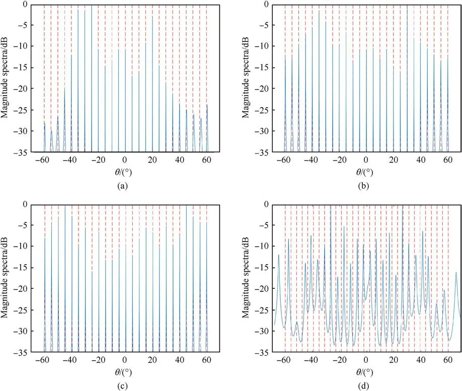
Fig.5.MUSIC spectra with different sampling intervals a: (a) a = 5, RMSE = 0.14; (b) a = 6, RMSE = 0.05; (c) a = 7, RMSE = 0.03; (d) a = 8.
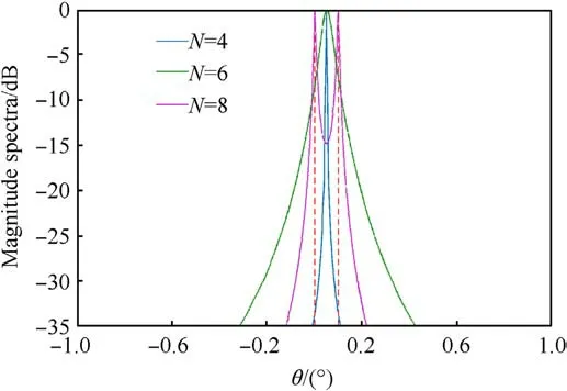
Fig.6.DOA estimation results with different N.
Table 3 presents the maximum UDOFs obtained using the nonuniform motion sampling scheme based on the optimal
According to Table 3, the DOFs of the synthetic array improve significantly as the number of sampling runs N of the array movement increases.
The difference co-array of the synthetic array obtained using the nonuniform motion sampling scheme based on the optimal second-level NA is non-porous and uniform,so the array aperture is proportional to the virtual array element number of the difference co-array,which depends on the motion sampling runs N.Therefore,when the array element spacing of ULA is d, the relationship between the maximum array aperture Dmaxand the motion sampling runs N can be written as follows:
In Eq.(25), the relationship between N1, N2and N is shown in Table 2, the maximum array aperture of the synthesized array increases with the increase of the number of sampling runs N.Therefore, with the increase of sampling runs N, the accuracy of DOA estimation is gradually improved.
However,during nonuniform motion sampling,it is necessary to ensure that the motion of the array position does not have a large impact on the target echo arrival direction, which would limit the number of motion sampling runs of array N.When the detection distance is R,the allowable angle error of the target is Δ;then,the maximum distance of array motion can be expressed as follows:
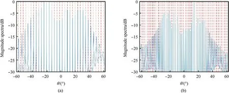
Fig.7.Number of targets estimated with different numbers of sampling runs N: (a) N = 4; (b) N = 6.
Then, the sampling runs of the array should satisfy the expressions N=N1+N2and d (a (N2N1+ N2- 1 ) + M - 1 ) ≤Lmax.
Table 4 shows the DOA computational complexity of three methods when the MUSIC algorithm is adopted for ULA.The three methods are respectively non-uniform motion sampling proposed in this paper, uniform motion sampling and initial ULA without motion sampling.Here only complex multiplication is considered and spectral peak search is ignored, so the number of complex multiplications is used to represent the computational complexity.When the resolution is the same,the three methods have the same aperture size and number of elements.
In Table 4,P is the number of snapshots,and a(N1N2+N2-1)+M is the number of nonnegative virtual elements in the synthetic array.The number of physical array elements in the original ULA is a(N1N2+N2-1) + M, and the number of array elements in the synthetic array of the uniform motion sampling ULA is a (N1N2+N2-1) + M, when both methods have the same resolution.
Fig.2 shows the computational complexity when the number of snapshots is 500.Fig.2(a)shows the complexity analysis performed considering the same number of sampling runs N(N = 4) but different numbers of physical array elements M.Fig.2(b)shows the complexity analysis performed with the same number of physical elements M(M=4)but different numbers of sampling runs N.With the same resolution and DOFs,the computational complexity of the proposed method is considerably less than that of the ULA based on physical array elements and the uniform motion sampling ULA.
A comparison of uniform with non-uniform motion sampling reveals that when the two methods finally synthesize the same virtual ULA,theoretically,they have the same resolution and DOFs,but uniform motion sampling requires more sampling runs.In practice, the value of each sampling point contains errors, so the greater the number of sampling runs,the higher is the accumulated error and the lower is the accuracy of the covariance matrix of the final received signal, which reduces the accuracy of DOA estimation.
4.Simulation and analysis
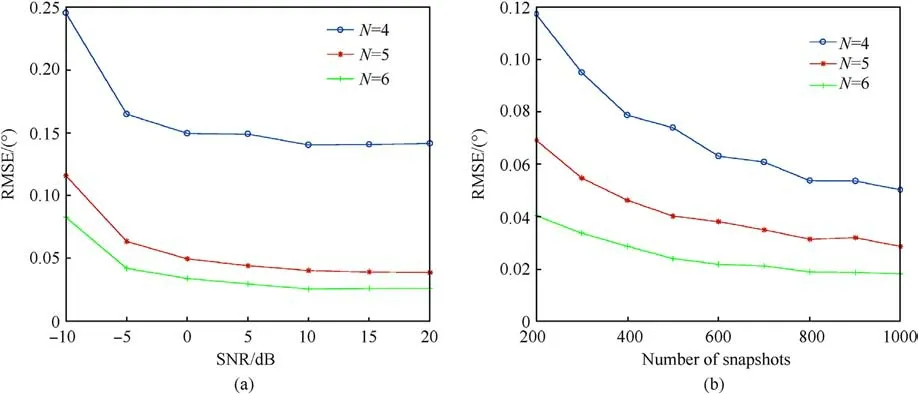
Fig.8.RMSE versus number of sampling runs N: (a) RMSE versus the number of SNR; (b) RMSE versus the snapshots.

Fig.9.Numbers of estimable targets for different M: (a) M = 4; (b) M = 5; (c) M = 6; (d) M = 7.
Several numeric simulations were conducted to assess the performance of the proposed algorithm.The simulation experiment scene is depicted in Fig.3.Along the movement direction of the UAV platform, a uniform linear receiving array with M array elements and a transmitting array were arranged,and the platform conducted nonuniform motion sampling in a manner similar to the optimal second-level NA.The specific parameters are listed in Table 5.
4.1.DOFs and redundancy of difference co-array
Fig.4 presents a comparison of the maximum UDOFs and redundancy in the synthesized difference co-array for different a,where M = 4.The abscissa represents DOFs of the array, and the ordinate weight function w (n ) represents the number of repetitions of an element in the difference co-array.The larger the value w(n),the higher is the redundancy.As a increases,the DOFs of the synthetic difference co-array increase, and the degree of redundancy decreases.When a >2M - 1 = 7, holes appear in the difference co-array.Therefore,when a =2M -1 = 7,the difference co-array has the maximum UDOFs and the minimum redundancy.
4.2.Comparison of DOA estimation performance
In this study, the high DOA resolution was achieved by expanding the aperture, which is unrelated to the specific DOA estimation algorithm.Therefore,the spatial smoothing MUSIC(SSMUSIC) algorithm was uniformly adopted to simulate and analyze DOA estimation performance.For the allowable angle error of 0.05°,the maximum movement distance of the array cannot exceed 0.44 m.Therefore,a(N2N1+N2-1) +M -1 ≤Lmax/d =229.5.
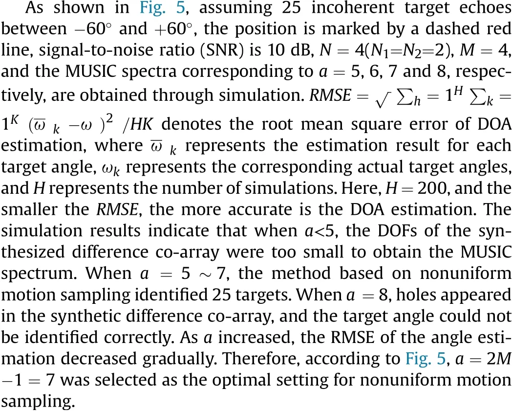
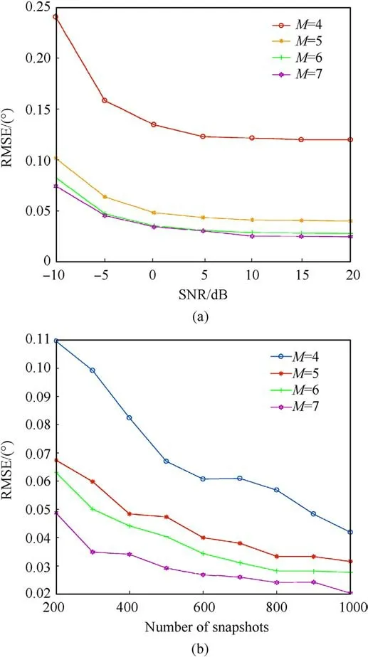
Fig.10.RMSE versus number of snapshots and SNR: (a) RMSE versus the SNR; (b)RMSE versus the number of snapshots.
Fig.6 depicts the MUSIC spectrum obtained with different numbers of sampling runs N when a =7 for two targets whose angles were 0.0°and 0.1°,separately.The sampling scheme was as follows:N=4 and (N1,N2) = (2,2);N=6 and (N1,N2) = (3,3);N = 8 and (N1,N2) = (4,4 ).The results indicated that as N increased,the DOA resolution of the synthetic array increased,and it was possible to resolve two targets when N = 8.
There were K targets with different angles between -60°and +60°, and the SS-MUSIC method was used to estimate the number of targets with different N, as depicted in Fig.7.The sampling scheme was as follows:N=4 and (N1,N2) = (2,2);N=6 and (N1,N2) = (3,3).The results indicated that when N=4,32 targets were identified.When N=6,74 targets were identified.As the number of sampling runs N increased,the DOFs of the synthetic array increased,and it was possible to identify a greater number of targets.
Assuming that 10 targets were evenly distributed between-60°and +60°, as depicted in Fig.8(a), the estimated RMSE of the DOA for different SNR levels and different numbers of sampling runs N.The number of snapshots was P = 400.Fig.8(b) depicts the estimated RMSE of the DOA for different numbers of snapshots and sampling runs N.Here, SNR = 10 dB.As the number of sampling runs N increased, the accuracy of DOA estimation gradually increased.

Fig.11.RMSE versus SNR for different methods.
Fig.9 shows the DOA estimation results obtained using the proposed method for a different number of physical array elements M.There existed K targets at different angles between -60°and +60°, and the number of targets was estimated using the SSMUSIC method, as shown in Fig.9(a).The sampling scheme was N=4 and(N1,N2)=(2,2).When M=4,32 targets were estimated;when M = 5, 41 targets were estimated; when M = 6, 49 targets were estimated; and when M = 7, 58 targets were estimated.In case of the proposed method, the number of estimable targets increased greatly as the number of physical array elements increased.This result can be achieved with a small number of sampling runs,and the increase in the number of estimable targets is more remarkable with a larger number of sampling runs.
Consider that 10 targets were evenly distributed between-60°and +60°, and N = 4.Fig.10(a) shows the estimated RMSE of the DOA for different SNR values and M.Here,the number of snapshots is P=400.Fig.10(b)shows the estimated RMSE of DOA for different P and M.Here,SNR=10 dB.From these results,we inferred that the accuracy of DOA estimation increased gradually as the number of physical array elements increased.
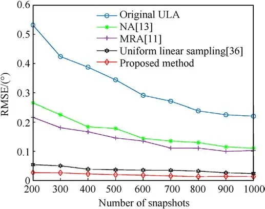
Fig.12.RMSE versus number of snapshots for different methods.
Fig.11 shows the comparison of DOA estimation performance between other typical methods and the proposed method under different SNR.Simulation parameters M=4,P=400,N=4,and the target angle is 30°.The results show that the proposed method has higher DOA estimation accuracy under different SNR,and has more obvious advantages under low SNR.
Fig.12 shows the comparison of DOA estimation performance between other typical methods and the proposed method under different number of snapshots.Simulation parameters M = 4,SNR=0,N=4,and the target angle is 30°.The results show that the proposed method has higher DOA estimation accuracy under different number of snapshots.In addition,it can be inferred from the above that the advantages of this method will become more obvious with the increase of sampling runs N.
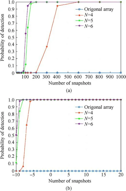
Fig.13.Probability of resolution versus number of snapshots and SNR: (a) Probability of resolution versus the number of snapshots; (b) Probability of resolution versus the SNR.
To further evaluate the underdetermined DOA estimation performance of the proposed method, the probability of successful target detection was determined by conducting multiple Monte Carlo experiments.The number of Monte Carlo iterations was 200,M = 4, N = 4-6, and 20 targets were uniformly distributed between -60°and +60°.Fig.13(a) shows the probability of successfully detecting a target with a different number of snapshots when SNR=-10 dB.The simulation results indicate that under the underdetermined condition, the original array always failed to detect the target.By contrast, as the number of snapshots increased, the probability of successfully target detection with the proposed method increased gradually, and as the nonuniform motion sampling number N increased, the probability increased gradually.Fig.13(b) shows the probability of successful target detection with different SNR values when the number of snapshots is P = 400.The simulation results indicate that under the underdetermined condition,the original array invariably failed to detect the target.By contrast, as the SNR increased, the probability of successful target detection using the proposed method increased gradually,and as the number of nonuniform motion sampling runs N increased, the probability increased gradually.
5.Conclusions
To improve the underdetermined DOA estimation performance of a moving small UAV platform, a nonuniform linear motion sampling method based on the optimal two-level NA was proposed by combining the concept of difference co-array and synthetic aperture technology.Theoretic analysis and simulation results indicated that with fewer sampling runs,the original array aperture can be expanded greatly, DOFs can be increased significantly, and underdetermined DOA estimation performance can be improved.However, the difference co-array synthesized using the proposed method contains a certain degree of redundancy,and the influence of the array element position error on the motion process requires further analysis, which will be accomplished in a future work.
Funding
The support projects are: National Natural Science Foundation of China(61973037);National 173 Program Project(2019-JCJQ-ZD-324).
Declaration of competing interest
The authors declare that they have no known competing financial interests or personal relationships that could have appeared to influence the work reported in this paper.
- Defence Technology的其它文章
- Explosion resistance performance of reinforced concrete box girder coated with polyurea: Model test and numerical simulation
- An improved initial rotor position estimation method using highfrequency pulsating voltage injection for PMSM
- Target acquisition performance in the presence of JPEG image compression
- Study of relationship between motion of mechanisms in gas operated weapon and its shock absorber
- Data-driven modeling on anisotropic mechanical behavior of brain tissue with internal pressure
- The effect of reactive plasticizer on viscoelastic and mechanical properties of solid rocket propellants based on different types of HTPB resin

