Numerical and experimental investigation into the evolution of the shock wave when a muzzle jet impacts a constrained moving body
Zijie Li, Hao Wang, Changshun Chen, Kun Jiang
School of Energy and Power Engineering, Nanjing University of Science and Technology, Nanjing 210016, China
Keywords:Shock wave/vortex interference Muzzle jet Constrained boundary Dynamic grid
ABSTRACT The gun-track launch system is a new special launch device that connects the track outside the muzzle.Because it is constrained by the track, the characteristics of development of the muzzle jet differ from those of the traditional muzzle jet.Specifically, it changes from freely developing to doing so in a constrained manner, where this results in an asymmetric direction of flow as well as spatio-temporal coupling-induced interference between various shock waves and the formation of vortices.In this background, the authors of this article formulate and consider the development and characteristics of evolution of the muzzle jet as it impacts a constrained moving body.We designed simulations to test the gun-track launch system, and established a numerical model based on the dynamic grid method to explore the development and characteristics of propagation of disturbances when the muzzle jet impacted a constrained moving body.We also considered models without a constrained track for the sake of comparison.The results showed that the muzzle jet assumed a circumferential asymmetric shape, and tended to develop in the area above the muzzle.Because the test platform was close to the ground,the muzzle jet was subjected to reflections from it that enhanced the development and evolution of various forms of shock waves and vortices in the muzzle jet to exacerbate its rate of distortion and asymmetric characteristics.This in turn led to significant differences in the changes in pressure at symmetric points that would otherwise have been identical.The results of a comparative analysis showed that the constrained track could hinder the influence of reflections from the ground on the muzzle jet to some extent,and could reduce the velocity of the shock waves inducing the motion of the muzzle as well as the Mach number of the moving body.The work here provides a theoretical basis and the requisite technical support for applications of the gun-track launch system.It also sheds light on the technical bottlenecks that need to be considered to recover high-value warheads.
1.Introduction
The combined gun-track launch system is a novel launch device that utilizes the capabilities of the gun and the rocket track to attain an environment with a high kinetic energy for the non-destructive recovery of warheads.It fills a gap in research on developing system-level launch overload and testing the capabilities of highvalue warheads [1,2].This launch device consists of a gun, a transition track,and a rocket track.The constrained track connected to the muzzle leads to a unique pattern of motion of the warhead.Specifically, it changes from open motion in full space to constrained motion.This in turn causes the muzzle jet of this launch system to have significantly different characteristics of transient development from those of the traditional muzzle jet [3,4].
The muzzle jet poses a series of challenges in aerodynamics owing to complex flows, such as shock-shock interference, strong moving shock waves,and strong vortices that play a dominant role in the flow field[5,6].Generally,the typical muzzle jet develops in a full space free field and has three-dimensional spherical symmetry.While in the new type of the gun-track launch system, influenced by the track outside the muzzle,the muzzle jet develops in a semifree field, exhibiting highly three-dimensional circumferential asymmetry and inducing multiple forms of vortices [7,8].In this study,the authors seek to provide insights into the complex flow in muzzle jets with constrained boundaries, from the perspectives of contributing to basic scientific research and solving key technical problems [9,10].It can be foreseen that under the interference of the track,the muzzle jet is filled with various forms of shock waves and vortices, which are greatly different from the traditional muzzle jet.The achievements of this article provide theoretical basis and necessary technical support for enriching the research connotation of muzzle jets.
Many researchers have extensively researched the mechanism of the muzzle jet by using numerical simulations and visualization experiments,and this work has led to a relatively systematic theory of the muzzle jet [11,12].The characteristics of transient evolution of shock waves due to interference in muzzle devices when a muzzle jet impinges on a moving body in full space have long been a subject of interest among researchers.Florio et al.[13]conducted numerical simulations to examine the influence of the port area of the exhaust and the arrangement of the muzzle device on the flow field by considering single-opening configurations of different sizes(located near the muzzle).Their results suggested that increasing the area of the opening reduced the radial range of the muzzle jet,while the radial flow of the lateral opening increased the expansion of the gas such that it diffused radially into the environment.A larger single-auxiliary opening was found to be more effective at reducing the pressure on the muzzle.
Guo et al.[14,15] systematically studied the flow field of a 7.62 mm small-caliber launcher with a cylindrical muzzle device that impacted a high-speed moving body in full space.They found that the vorticity in the flow field was mainly concentrated along the boundary of the jet,and many small-scale vortices were formed downstream of the Mach disk.
Zhang et al.[16,17] used large eddy simulations to describe the characteristics of the flow field during interactions between a supersonic mainstream and a transverse jet, and derived the law of evolution in the morphology of the 3D shock wave.Their results showed that the front edge of the jet was formed owing to a bow shock and a "λ" separation shock arising from the strong adverse pressure gradient.
Li et al.[18,19] examined the development of a 300-mm-caliber muzzle jet placed close to the ground.They found that the shock wave of the muzzle reflected off the ground to form a shock wave with the opposite direction of propagation.A new wavefront was formed when the shock wave generated by the reflection from the ground intersected with the shock wave of the muzzle.A vortex was formed near the new wavefront, and the entire strong, unsteady supersonic flow field exhibited highly asymmetric characteristics to aggravate the initial disturbance of the moving projectiles.
A key finding of the brief review of the literature provided above is that the characteristics of the shock wave during the impingement of the muzzle jet on a freely moving body have received significant attention in research.However, few studies have investigated the mechanisms of development and evolution of shock waves and vortices during the impingement of a muzzle jet on a constrained moving body.In light of the complex phenomena of flow caused by the constrained boundary in the muzzle jet, the authors of this study establish a physical test system to examine the related issues.The key feature of this study is that the transient evolution of shock waves in the flow field is revealed by building a physical test system and a simulation model involving constrained moving bodies.
The remainder of this paper is composed of four sections.Section 2 provides a detailed introduction to the physical and computational models, boundary conditions, and methods of solution used here.Section 3 introduces the physical test,including the test equipment and plan.Section 4 provides a discussion of the results of the test and simulations of the characteristics of evolution of shock waves when a supersonic jet impacts a high-speed constrained moving body,including the structure of the muzzle jet, the characteristics of evolution of the shock wave, the generation and evolution of vortices,and transient changes in pressure at crucial points.Finally,Section 5 summarizes the conclusions of this study.
2.Physical and mesh models
2.1.Physical model
We established two models for this study.Case 1 involved a model of simulation corresponding to the structure of the test system, while Case 2 considered a simulation model without a constrained track for the sake of comparison.Except for the difference in the constrained track, both models had the same structure and size.Particular emphasis was placed on the structures and sizes of the inlet of the jet and the moving body.
Fig.1(a)provides a schematic diagram of the 3D physical model(Case 1) studied in this article.It included a constrained track, a tube, and a support frame.The diameter of the muzzle was 65.0 mm, and the constrained track had a "工" shape and was 200 mm long.The moving body was cylindrical,100 mm long,and was cut into the structure of the track.Fig.1(b)shows the physical model without a constrained track that was used for comparison(Case 2).
The physical structure used for the numerical simulations was constructed according to the geometry of the test system,as shown in Fig.2.Fig.2(a) shows the physical structure and size of the computational domain,while Figs.2(b)and 2(c)show details of the local models for both cases.The computational domain was sufficiently large in all three directions to prevent boundary effects.
2.2.Dynamic grid method
The dynamic grid method was used to handle changes in the computational grid caused by the motion of the body during the calculations.The dynamic grid algorithm was used to determine the requisite adjustment to the internal nodes of the grid.Three algorithms are available to this end: the layering method, the smoothing method, and the remeshing method.The layering method can best simulate the motion of the body because it represents only translational motion along one direction.
It is necessary to set the factors of segmentation and merging of the grid in the layering method.Due to the body's motion,the grid behind the body shifts forward along the x-axis.This results in the elongation of a grid layer near the bottom of the moving body,with a grid edge of length hs.A grid layer near the top of the moving body is simultaneously compressed,with an edge of the grid of length hc.Assuming that the ideal length of the edge of the grid is hi,the grid is divided into two when the size of the newly generated grid satisfies h>(1+Cs)hi.When the grid size satisfies h <Cshi, adjacent grids are merged into one.In this study,hi=5.0 mm,Cs=0.4,and Cl= 0.2.
2.3.Grid model
We conducted calculations on half of the domains of the models to save time and cost.Fig.3 shows a schematic diagram of the grid model.The computational domain was discretized by using structured grids, with approximately 9.8 million cells in total.When simulating complex 3D flow fields containing moving bodies,generating a single, high-quality, structured grid domain is often difficult, and the grids are divided and spliced for ease of processing.The computational domain was divided into stationary and dynamic grid domains,and numerical exchange was carried out by using these interfaces.

Fig.1.3D physical models of Case 1 and Case 2: (a) Case 1; (b) Case 2.
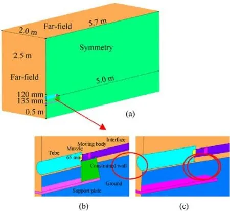
Fig.2.Simulated physical structure of the model:(a)Physical structure and size of the computational domain; (b) Local physical structure for Case 1; (c) Local physical structure for Case 2.
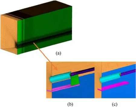
Fig.3.Schematic diagram of the model of the grid:(a)Entire domain;(b)Track in Case 1; (c) Track in Case 2 (no track).
2.4.Boundary conditions and solution methods

Fig.4.Boundary conditions of the model of the muzzle jet.
Fig.4 shows the types of boundaries used in the model.The domain and outlet of calculation were modeled as the boundary conditions at the outlet of pressure,while the tube and constrained track were assumed to be non-slip walls.The boundary condition of a moving wall was applied to the moving body,it was controlled by a program with six degrees of freedom(DOF),and its initial speed was 500 m/s.The boundary at the inlet of pressure was applied to the muzzle,and its pressure was 45 MPa according to data from the test.Moreover,according to the after-effects model of the gun,the variation in the pressure of the muzzle over with time was specified as p = 45.0× 10⁶exp(- 24.886t).
In this article, on the basis of the finite volume method, the overall motion processing method of block mesh division was adopted, combined with the structural dynamic method.The Navier-stokes (N-S) equation solver based on density correction was selected, as well as K-ε Realizable turbulence model.The inviscid convective flux is split by Roe-FDS scheme, and the time marching method uses implicit scheme to accelerate the convergence of numerical calculation.The flow control equation is discretized by the second-order upwind scheme, and the material is an ideal gas.
3.Analysis of results
3.1.Test equipment
A test system involving a muzzle jet impinging on a high-speed moving body with constrained boundaries was developed and designed based on the combined gun-track launch platform.Fig.5 shows that the test device was a 65-mm-caliber gun.A constrained track was installed at the muzzle to construct special constrained boundaries, as shown in Fig.6.
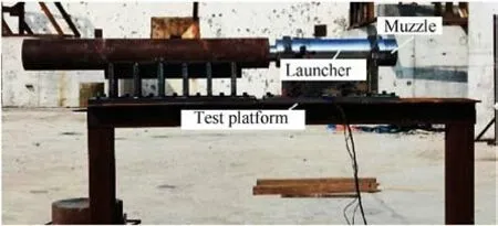
Fig.5.Photograph of the testing device.
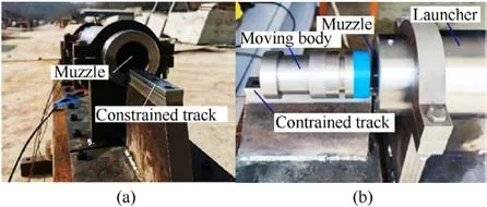
Fig.6.Photographs of the constrained boundary and the moving body:(a)Photograph of the constrained boundary; (b) Photograph of the moving body.
3.2.Test equipment
Fig.7 illustrates the test plan.The test platform was the main generator of the jet, and the moving body was pushed out of the muzzle at about 500 m/s.The muzzle was externally connected to the constrained track,and the moving body ran on the constrained track after exiting the muzzle.Dynamic pressure sensors were installed at key points on both sides of the constrained boundary to monitor changes in the transient pressure of the flow field.A piezoelectric dynamic pressure sensor,manufactured by the Kistler company, was used to measure the over-pressure signals.All pressure signals were collected by a DEWE2-A13 transient data recorder manufactured by DEWETRON Industrial Equipment Company(Austria).A photon high-speed camera was used for highspeed photography,and had a frame rate of 5000 fps to capture the formation and development of the over-pressure field.
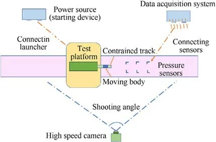
Fig.7.Illustrates the test process as captured by the high-speed camera.
The moving body had just emerged from the muzzle in Fig.8(a),marking the beginning of the experiment.At this point,the muzzle jet had just begun to form.Fig.8(b) shows that the moving body flew away from the muzzle, and high-pressure and hightemperature gas along with smoke were ejected from it, and impacted the moving body.With the movement of the high-speed body and the development of the jet, the muzzle jet came into contact with the ground and produced a reflective wavefront in the opposite direction, as is shown clearly in Figs.8(c)-8(e).The new wavefront continued to develop upward,and was clearly presented on the background plate.This was clearly an interference in the development of the muzzle jet.As the latter developed, the reflected waves formed a local high-pressure zone below the muzzle.The results of the numerical simulations to follow will examine this phenomenon in detail.Figs.8(e)-8(f) show that the moving body gradually flew away from the muzzle over time,and the muzzle jet eventually died out as the gunpowder ran out.
The changes in pressure at key points were also monitored during the test.Fig.9 compares the changes in pressure over time between the test and the simulations at point(1500,30,10)mm.It is clear that they were in good agreement.Therefore,the method of simulation used here could accurately simulate the characteristics of the muzzle jet of the combined gun-track launch system.
4.Results of numerical simulations
Based on the above engineering background, the authors consider the problem of the development and evolution of shock waves and vortices during the impingement of the jet on a constrained moving body through numerical calculations.Figs.10 and 11 show the pressure contours of the muzzle jet on the plane of symmetry in Case 1 and Case 2.The moving body had just moved out of the muzzle in Figs.10(a)-10(b) to form a preliminary flow field.However, the muzzle jet was insufficiently developed, and had a short range of impact.Gas was ejected from the muzzle,and impacted the moving body, pushing the surrounding air to form a“half”-spherical shock wave and a front shock wave ahead of the moving body.Meanwhile,a shock wave was also formed in front of the moving body, and had a regular wavefront with a spherical shape but was truncated on the track.
Figs.10(c)-10(d)show that the muzzle jet gradually developed,and its asymmetry became increasingly apparent.Under interference from the constrained track, the support frame, and the test platform, the jet tended to develop significantly toward the upper part of the muzzle.Although the constrained track in the test was not very long,the development of the shock wave still depended on it.The initial disturbance distorted the shock wave of the muzzle,and changed it from a circumferential symmetric form to a circumferential asymmetric form.Figs.10(e)-10(f) show that because the test platform was 0.5 m from the ground, the shock wave of the muzzle was launched when it encountered the ground,and this caused it to propagate upward to form a new wavefront.An asymmetric, complete wave system was formed around the muzzle, and included coronal shock waves, reflected shock waves,Mach disks, and discontinuities.
Fig.11 clearly shows the differences between the structures of the flow fields of the models.As is shown in Fig.11(a),there was no constrained track outside the muzzle in Case 2, and the flow field was thus roughly symmetrical.However,the two models otherwise had the same structure and size.Therefore, the muzzle was not a complete circle,but a circular structure with bosses that conformed to the shape of the moving body such that the muzzle jet was not completely symmetrical.
Figs.11(b)-11(c) show that the muzzle jet clearly developed fully toward the lower area of the muzzle in Case 2, in contrast to Case 1.As is shown in Fig.11(d),the range of influence of the muzzle jet without the constrained track was significantly larger than that in Case 1.It is evident from Figs.11(e)-11(f)that the shock wave of the muzzle was launched when it came into contact with the ground.This led to the formation of a new wavefront that propagated upward to influence the development and evolution of the mainstream.The impact of the ground on the flow field in Case 2 was significantly greater than that in Case 1.From this, we can gather that the asymmetry in Case 2 was mainly caused by the muzzle being too close to the ground, and resulted from the joint action of the ground and the constrained track in Case 1.
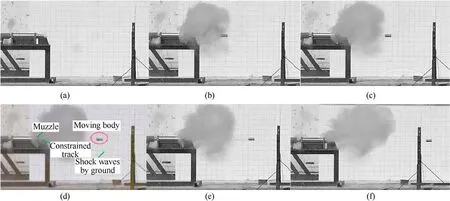
Fig.8.Representative visualized results of the test.
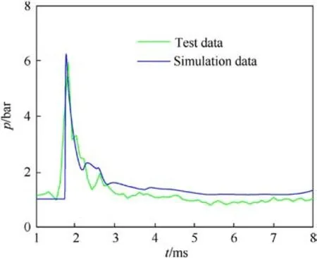
Fig.9.Comparison of the changes in pressure at a key point over time between the test and the simulation.
Figs.12 and 13 show the evolution of vortices on the plane of symmetry.As is shown in Figs.12(a)-12(b), the vortices were generated in the flow field of the muzzle over time.Due to interference by the constrained track, the support plate, and the test platform,there were significant differences in the morphologies of the vortices above and below the muzzle.The figure shows that both vortices were located in the low-pressure zone.The streamline was directed outward from the center of the vortex in the area above the muzzle.The spiral point was stable,and was resistant to dissipating.In the area below the muzzle, the streamlines of the vortex pointed outward from its center.The spiral point was again stable, and was resistant to dissipating
Figs.12(c)-12(e) show that significant changes occurred in the development of vortices in the flow field over time.The vortex above the muzzle still evolved steadily, with the streamlines directed outward from its center.The spiral point was stable, and did not easily dissipate.However, the streamlines of the vortex below the muzzle pointed toward its center from the outside owing to continuous interference by ground-reflected waves, and this caused the spiral point to become unstable and easily dissipate.

Fig.10.Pressure contours of the muzzle jet on the plane of symmetry over time in Case 1: (a) t = 0.1 m; (b) t = 0.2 m; (c) t = 0.5 m; (d) t = 1.0 m; (e) t = 2.0 m; (f) t = 3.0 m.

Fig.11.Pressure contours of the muzzle jet on the plane of symmetry over time for Case 2: (a) t = 0.1 m; (b) t = 0.2 m; (c) t = 0.5 m; (d) t = 1.0 m; (e) t = 2.0 m; (f) t = 3.0 m.

Fig.12.Evolution of vortices in a symmetric muzzle jet over time: (a) t = 0.5 m; (b) t = 1.0 m; (c) t = 2.0 m; (d) t = 3.0 m; (e) t = 3.5 m.

Fig.13.Evolution of vortices in a symmetric muzzle jet over time: (a) t = 0.5 m; (b) t = 1.0 m; (c) t = 2.0 m; (d) t = 3.0 m; (e) t = 3.5 m.

Fig.14.Schematic diagram of reflection of the shock wave.
As expected,a clear difference was observed in Case 2.First,no prominent vortices were induced due to the absence of the constrained track in Case 2.For example,Fig.13(b)shows that a distinct vortex was generated below the constrained track in Case 1, but was absent in Case 2.Second, Fig.13(c) shows that the vortex induced below the constrained track in Case 1 developed and evolved over time owing to its stable spiral point, but no such phenomenon was noted in Case 2.Instead,small disturbances were generated on the ground.This also indicates that the impact of the surface of the ground on the flow field in Case 2 was significantly greater than in Case 1.
Over time, the vortices induced by the ground in Case 2 continued to develop.They were all located in the low-pressure area, and the streamline pointed outward from the center of the vortex.The spiral point was stable, which means that it did not easily dissipate.From this, it can be concluded that the rate of distortion of the constrained muzzle jet was high,and it was prone to generate vortices.
Three types of shock waves are emitted when a flow field encounters a rigid wall:normal reflection,regular reflection,and Mach reflection.When normal reflection occurs,the pressure at the point of reflection increases sharply, and leads to the simultaneous formation of a reverse shock wave that propagates upward.In case of regular reflection, the phenomena that occur vary owing to the different angles of reflection.As the angle of reflection increases,the reflected shock wave is forced to move up to a certain distance from the point of reflection: This is called Mach reflection.When Mach reflection occurs,the reflected wave is separated from the solid wall,and a third wave, in addition to the incident and reflected waves,appears near the fixed wall.This is the Mach rod(see Fig.14).
The pressure wave generated by the muzzle jet on the ground is shown in Fig.15.The previous test images(Fig.8)also show that the shock wave of the muzzle encountered the ground and generated a strong reflected wave that formed a new wavefront and continuously propagated upward.The results of the numerical simulations validated this phenomenon.As is shown in Fig.15(a), the shock wave of the muzzle was reflected when it encountered the ground to form a new shock wave front that generated local high pressure above the ground.The new wavefront continued to develop upward to increase the area of high pressure below the muzzle and generate a corresponding pressure wavefront on the ground.Over time, the angle of reflection increased, the reflected shock wave shifted upward, detached from the reflection point, and formed a Mach rod as shown in Figs.15(c)-15(d).Behind the Mach rod was a zone of local high pressure that contained a large amount of energy.
The difference in Case 2 is evident.The shock wave of the muzzle had just spread to the ground in Fig.15(a)in Case 1 due to obstruction from the restraining rail, while the shock wave of the muzzle spread to the ground and reflection occurred in Case 2(Fig.16(a)).The opposite wavefront spread upward to gradually influence the main flow field.As is shown in Fig.16(b), the difference was more pronounced.A Mach rod had already formed, and created a local high-pressure zone that had a stronger and earlier impact on the development and evolution of the mainstream.The positions of the three wave points and the speed of the Mach rod changed over time, and the height of the latter continued to increase.
To further illustrate the impact of the constrained boundary on the muzzle jet, the changes in pressure at several key points were monitored over time for comparative analysis.Fig.17 is a schematic diagram of the locations of the monitoring points and Table 1 lists them.
Figs.18(a)-18(d)compare the changes in pressure over time at the key points in Case 1.The curve of pressure,which should have been consistent, had changed due to the influence of both the constrained boundary and the ground.
The figure shows that the muzzle jet tended to develop upward due to the obstruction of the transition track,because of which the monitoring points above the muzzle always recorded the disturbance of the shock wave earlier than those below the muzzle.As is shown in Fig.18(a),the speed of the moving body was about 500 m/s,and the shock wave thus moved to this monitoring point at about 3 m.Its impact was felt immediately at this point, and led to an increase in pressure.The maximum pressure at Point A-abovewas slightly higher than that at Point A-belowbecause the constrained track hindered the downward movement of the muzzle jet,causing it to propagate upward.
The pressure at the monitoring point subsequently decreased and then increased slightly at about t = 6.0 m.The increase in pressure at Point A-abovewas significantly greater than that at Point A-below, but then rapidly decreased.Due to the influence of the ground,the high-pressure area at Point A-belowwas relatively large,and led to relatively high pressure.Meanwhile, the pressure at Point A-belowwas supplemented by the reflected waves such that the fluctuations in pressure were relatively minor.Over time, the shock wave gradually advanced and the pressure at Point A became more steady.
Fig.18(b) shows that the shock wave moved to Point B at approximately t=4.0 m.The monitoring point recorded its impact,and the pressure increased to reach a maximum of around 1.7 bar.Due to the proximity of monitoring point B to the centerline of the jet, the difference in pressure at its point of symmetry was relatively small compared with those at the other monitoring points.
Fig.18(c)shows that at approximately t=4.0 m,the shock wave moved to Point C and the change in pressure at Point C-belowwas smoother than that at Point C-above.The disturbance due to the shock wave continued over time because of the relatively large distance between Point C and the centerline of the jet.As is shown in Fig.18(d), the maximum pressure at Point D-belowwas greater than that at Point D-abovebecause Point D was far from the muzzle,and the muzzle jet had developed more fully and was affected by the ground.The range of high pressure in the lower area was relatively large.Therefore, the maximum pressure at the lower monitoring point was greater than that at the upper monitoring point.
However, in Case 2 (Figs.19(a)-19(d)), the asymmetric characteristics of the upper and lower points of symmetry were different.Of the four monitoring points,the maximum pressure at the lower monitoring point was higher than that at the upper monitoring point.In Case 1, however, this situation held only for Point D.Another point worth noting is that the maximum pressure at the lower monitoring points in Case 2 was higher than that in Case 1,indicating that the impact of the ground on the jet flow occurred much earlier in Case 2 than in Case 1.
Another generalized characteristic is that the differences between all upper and lower symmetric monitoring points in Case 2 were smaller than those in Case 1 because Case 2 did not involve the influence of the constrained track on the jet flow.
As an example, Figs.20(a)-20(d) compare the changes in pressure over time at Point A and Point C in Case 1 and Case 2.Figs.20(a)-20(b)(Point A-aboveand Point A-below)clearly show that the difference in pressures at Point A-abovebetween the cases was smaller than that at Point A-below.The same applies to Point C-aboveand Point C-below(Figs.20(c)-20(d)).There were still significant differences in the changes in pressure at the same monitoring points, indicating that there were indeed differences in the development and evolution of the muzzle jet between Case 1 and Case 2.This indirectly proves that the constraining rail had a significant impact on the development of the muzzle jet.The figure shows that the change in pressure at the monitoring point in Case 2 occurred earlier than that in Case 1, indicating that the shock wave had propagated more quickly in Case 2 than in Case 1.This shows that the constrained boundary hindered the speed of propagation of the shock wave.

Fig.15.Pressure wave generated by the ground: (a) t = 2.0 m; (b) t = 3.0 m; (c) t = 3.5 m; (d) t = 4.2 m.

Fig.16.Pressure wave generated by the ground: (a) t = 2.0 m; (b) t = 3.0 m; (c) t = 3.5 m; (d) t = 4.2 m.

Fig.17.Schematic diagram of the locations of the monitoring point.

Table 1 Locations of the monitoring points on the track.
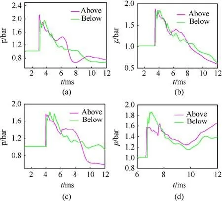
Fig.18.Comparisons of pressure at each monitoring point over time for Case 1: (a)Point A; (b) Point B; (c) Point C; (d) Point D.
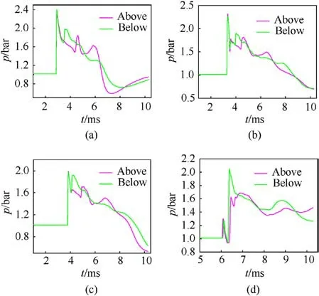
Fig.19.Comparisons of pressure at each monitoring point over time for Case 2: (a)Point A; (b) Point B; (c) Point C; (d) Point D.
The posture of the moving body was also a primary concern.We monitored such parameters as the lift force, drag force, and Mach number of the moving body in Case 1 and Case 2.Fig.21 shows the significant differences in these parameters between the cases.Fig.21(a)shows that the lift on the moving body in Case 1(with the constrained track) was significantly lower than that in Case 2 (no constrained track).Case 1 featured a minor increase in lift at the beginning because the body was moving on the constrained track and then flew freely out of it.Fig.21(b)shows that the drag force on the moving body in Case 1 was significantly larger than that in Case 2 at the beginning.This was also reflected in the difference in the Mach number between the cases(Fig.21(c)).The Mach number of the moving body in Case 2 was larger than that in Case 1 because of the constrained track in the latter case.Previous work has also shown that the shock wave of the muzzle without a constrained track is faster, and thus poses a higher resistance to the motion of the body.
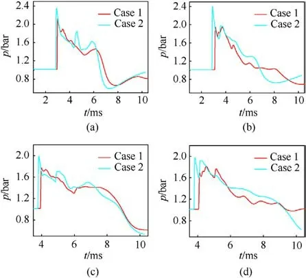
Fig.20.Comparisons of pressure at the monitoring points over time in Case 1 and Case 2: (a) Point A-above; (b) Point A-below; (c) Point C-above; (d) Point C-below.
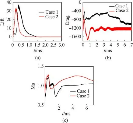
Fig.21.Lift, drag, and Mach numbers for the moving body over time in Case 1 and Case 2: (a) Lift; (b) Drag; (c) Mach number.
5.Conclusions
In this study, the authors conducted a physical test and performed numerical simulations to examine the characteristics of a recently developed combined gun-track launch system.A dynamic grid method was used to examine the characteristics of evolution of the shock waves and vortices in case of a muzzle jet impacting a constrained moving body.The results yielded the following conclusions.
(a) Owing to the constrained boundary,the spherical muzzle jet,which should have been circumferentially symmetric, was deformed,and leaned toward the upper part of the center of the muzzle.
(b) Lateral flow was generated in the flow field due to obstruction by the constrained boundary, and a vortex was generated along the constrained track.The characteristics of evolution of the vortex were unique, and distinguish this design from that of the traditional muzzle jet.
(c) Due to the proximity of the test platform to the ground,the muzzle jet was reflected from it to form a new wavefront of pressure that increased the high-pressure area below the muzzle,and in turn enriched the characteristics of evolution of the shock waves and vortices in the asymmetric muzzle jet.A complete shock wave of pressure was also formed on the ground.However, the constrained track hindered the development of the downward flow of the muzzle, thus reducing the high-pressure area generated by the reflection of the shock wave from the ground.
(d) The constrained track influenced the development and evolution of the muzzle jet,and this was directly manifested by differences in pressure at the monitoring points between the cases and a reduction in the velocity of the shock wave.At the same time,it influenced the posture of the moving body by reducing the resistance to its motion and its Mach number.
Declaration of competing interest
No conflict of interest exits in the submission of this manuscript entitled "Numerical and experimental investigation into the evolution of the shock wave when a muzzle jet impacts a constrained moving body", and manuscript is approved by all authors for publication.I would like to declare on behalf of my co-authors that the work described was original research that has not been published previously, and not under consideration for publication elsewhere,in whole or in part.All the authors listed have approved the manuscript that is enclosed.
Data availability
All data and models that support the findings of this study are available from the corresponding author upon reasonable request.All data and models generated or used during the study appear in the submitted article.
- Defence Technology的其它文章
- Explosion resistance performance of reinforced concrete box girder coated with polyurea: Model test and numerical simulation
- An improved initial rotor position estimation method using highfrequency pulsating voltage injection for PMSM
- Target acquisition performance in the presence of JPEG image compression
- Study of relationship between motion of mechanisms in gas operated weapon and its shock absorber
- Data-driven modeling on anisotropic mechanical behavior of brain tissue with internal pressure
- The effect of reactive plasticizer on viscoelastic and mechanical properties of solid rocket propellants based on different types of HTPB resin

