Predicting the electromechanical properties of small caliber projectile impact igniter using PZT dynamic damage constitutive model considering crack propagation
Rui-zhi Wng , Zhi-qing Wng , En-ling Tng *, Lei Li , Guo-li Yng ,Chun Cheng , Li-ping He , Y-fei Hn
a Key Laboratory of Transient Physical Mechanics and Energy Conversion Materials of Liaoning Province, Shenyang Ligong University, Shenyang,110159,Liaoning, China
b School of Mechanical Engineering, Nanjing University of Science and Technology, Nanjing, 210094, Jiangsu, China
c Key Laboratory of Impact and Safety Engineering, Ministry of Education, Ningbo University, Ningbo, 315211, Zhejiang, China
Keywords:Piezoelectric ceramics Impact Igniter Dynamic damage constitutive model Electromechanical response
ABSTRACT Block piezoelectric ceramics (PZTs) are often used in impact igniters to provide activation energy for electric initiators.Under the action of strong impact stress, PZTs release electric energy accompanied by crack initiation, propagation and crushing.At present, the electrical output performance of PZTs in projectile is usually calculated by quasi-static piezoelectric equation without considering the dynamic effect caused by strong impact and the influence of crack propagation on material properties.So the ignition parameters are always not accurately predicted.To tackle this, a PZT dynamic damage constitutive model considering crack propagation is established based on the dynamic impact test and the crack propagation theory of brittle materials.The model is then embedded into the ABAQUS subroutine and used to simulate the electromechanical response of the impact igniter during the impact of a small caliber projectile on the target.Meanwhile, the experiments of projectile with impact igniter impact on the target are carried out.The comparison between experimental and numerical simulation results show that the established dynamic damage model can effectively predict the dynamic electromechanical response of PZTs in the missile service environment.
1.Introduction
Polycrystalline doped lead zirconate titanate ceramics (PbZr1-xTixO3,PZT)are widely used in various sensors,actuators and pulse power supplies due to their excellent mechanical and electrical conversion properties[1-3].In these applications,electrical energy is stored in PZTs during initial polarization and released into the electrical load by external stress loading.Based on the special electro-mechanical, they usually bear the stress pulse effect in the application process, such as high-frequency resonance excitation,vibration and impact [4-7].Especially in the field of national defense industry, PZTs may withstand high-pressure stress pulses such as overload stress[8,9],shock wave[10-13],detonation wave[14,15], etc.People use the electric output performance of PZTs under high-pressure stress pulses to realize the unique functions of devices, which leads to the emergence of pulse igniters, explosive transducers and piezoelectric power supplies [16-18].
PZT based launch/impact igniters is one of the typical applications [19].When the projectile is launched or hits the target, the mass above/below the PZT has backward/forward acceleration,and compresses the PZT under the coupling action of impact stress and inertial force.The PZT generates a large amount of charge based on the piezoelectric effect, and then activates the electric explosive device(EED).How to determine and predict the electro-mechanical behavior of PZTs under pulse stress is the key problem to solve the reliability of pulse igniter.
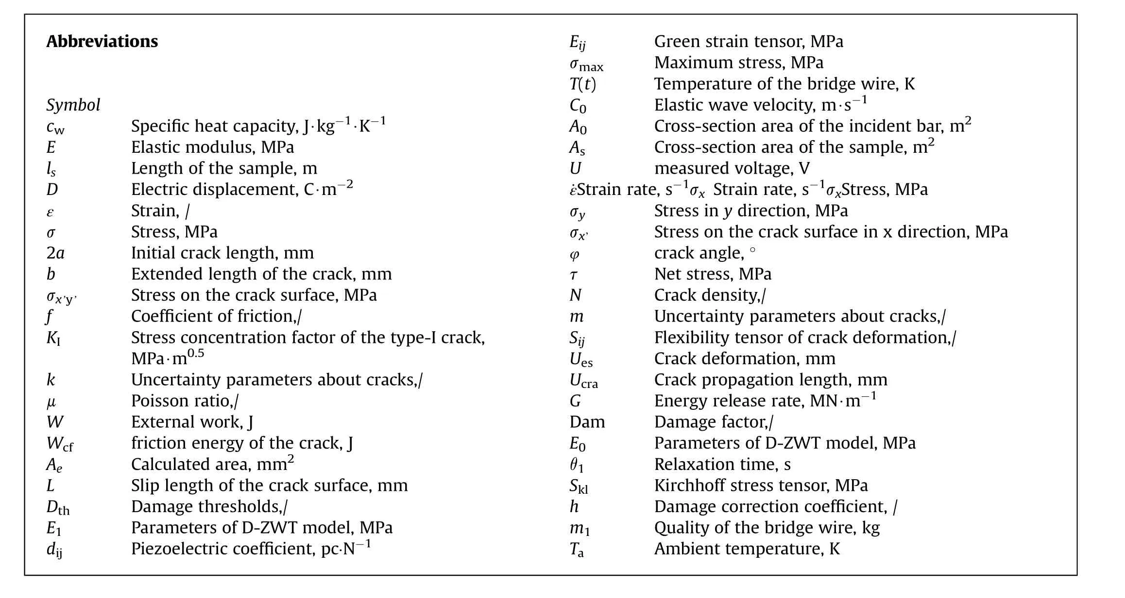
Abbreviations Symbol cw Specific heat capacity, J∙kg-1∙K-1 E Elastic modulus, MPa ls Length of the sample, m D Electric displacement, C∙m-2 ε Strain, /σ Stress,MPa 2a Initial crack length,mm b Extended length of the crack, mm σx’y’ Stress on the crack surface, MPa f Coefficient of friction,/KI Stress concentration factor of the type-I crack,MPa∙m0.5 k Uncertainty parameters about cracks,/μ Poisson ratio,/W External work, J Wcf friction energy of the crack, J Ae Calculated area, mm2 L Slip length of the crack surface, mm Dth Damage thresholds,/E1 Parameters of D-ZWT model, MPa dij Piezoelectric coefficient, pc·N-1 Eij Green strain tensor, MPa σmax Maximum stress,MPa T(t) Temperature of the bridge wire, K C0 Elastic wave velocity, m∙s-1 A0 Cross-section area of the incident bar, m2 As Cross-section area of the sample, m2 U measured voltage,V ˙εStrain rate,s-1σx Strain rate,s-1σxStress,MPa σy Stress in y direction, MPa σx’ Stress on the crack surface in x direction, MPa φ crack angle, °τ Net stress,MPa N Crack density,/m Uncertainty parameters about cracks,/Sij Flexibility tensor of crack deformation,/Ues Crack deformation, mm Ucra Crack propagation length, mm G Energy release rate, MN∙m-1 Dam Damage factor,/E0 Parameters of D-ZWT model, MPa θ1 Relaxation time, s Skl Kirchhoff stress tensor, MPa h Damage correction coefficient, /m1 Quality of the bridge wire, kg Ta Ambient temperature,K
The piezoelectric response of PZTs includes linear and nonlinear relations.Linear relationship is generally confined to relatively low levels of applied electric field and stress,under which the dielectric,elastic and piezoelectric relationships are described well by the standard piezoelectric constitutive equations.Nonlinear relationships are observed above certain'threshold'values of electric field strength and mechanical stress field and stress-dependent dielectric (ε), elastic (S) and piezoelectric (d) coefficients [20].With the development of PZT in the field of national defense, the nonlinear behavior has greatly affected the design and performance evaluation of equipment in the early stage, and has gradually attracted attention.Great progress has been made in the study of the nonlinear electro-mechanical response constitutive model of PZTs[21-23].It exhibits significant history-dependent nonlinearities such as the well-known dielectric, butterfly and ferroelastic hystereses due to switching processes.Researchers have established a variety of nonlinear constitutive relations,which involve the highorder effect of piezoelectric equation[24,25],hysteresis effect[26],mechanical depolarization effect [27] and the influence of nonlinear crack propagation [28].
Numerous studies have shown that the nonlinear stress-strain characteristics of PZT in the working process largely affect the release of electrical energy.The detailed study on the hysteresis behavior of the stress-strain curve by Fan J et al.[29]shows that the ferroelastic non 180°polarization inversion process is a smooth softening process and the saturation inversion process is a gradual hardening process, respectively.Based on the underlying physical mechanism, this nonlinear behavior can be simulated by a mechanical model, which is composed of several parallel Maxwell chains.Each chain includes a nonlinear spring and a friction slider.The generalized displacement of the slider, which represents the internal variable, is introduced to describe the local process of the cooperative switching of the corresponding grain groups.And based on this,the hardening and softening process is controlled by the change of the nonlinear spring stiffness.From the above description,the nonlinear behavior of this force electric conversion is very similar to the isothermal nonlinear viscoelastic constitutive model between stress and strain, namely Zhu Wang Tang (ZWT)constitutive model.On this basis, a viscoelastic constitutive model considering the strain rate effect were established, and the model parameters were determined through experiments [11].However,the related models do not consider the effects of crack propagation and damage effects.
In this paper, the influence of crack propagation process and damage effect is further considered on the basis of the ZWT model.Accordingly, a dynamic damage constitutive model of PZT considering crack propagation is established, and.The parameters of the model are determined by the split Hopkinson pressure bar(SHPB)experiment.Furthermore, the dynamic constitutive model is written into ABAQUS material subroutine and the mechanical and electrical responses of small caliber ammunition impacting the target are numerically simulated.Finally, corresponding tests are carried out and the test results are compared with the numerical simulations.
2.Impact igniter for small caliber ammunition
2.1.Structures of the ammunition and the impact igniter
A self-powered projectile borne impact igniter suitable for small caliber ammunition is designed based on the piezoelectric effect,as shown in Fig.1.
The impact igniter based on piezoelectric ceramics has the characteristics of simple structure, small ignition delay, and high reliability.When applied in small caliber ammunition, it can replace the traditional impact fuze and reduce the volume and quality of the ignition device in the projectile.It is the key to improve the miniaturization and intelligent level of the ammunition.The main components of the igniter include:PZT,mass block,EED, shell, wire and insulation device.When the impact igniter is placed in the projectile, the switch mode can be selected through the dowel.When the dowel is locked,the mass block has no load on the PZT, and the igniter is closed; When the dowel is released, the mass block compresses the PZT under the impact overload force of the projectile,and the EED is activated by the electric energy output by the PZT.The upper and lower surfaces of the PZT are pasted with copper foil electrodes and connected with the EED through flexible wires.The electrodes, the shell and the mass block are insulated with polyimide films.The head of the impact igniter is provided with threads for quick assembly with the device to be ignited.

Fig.1.Structures of projectile and impact igniter.
The small caliber projectiles used in the experiment mainly include impact igniter, projectile body and Al/PTFE powder.Wherein the mass block is a tungsten alloy cylinder with a diameter and a thickness of 7 mm and 4 mm,respectively;the EED is military 2#electric ignition head,and its parameters are shown in Table 1.The diameter of the projectile is 16 mm,the thickness of the shell is 1.5 mm,and the head of the projectile is oval with a cone angle of 20°.In order to facilitate the observation of the reaction process,two through holes with a diameter of 2 mm are set in the head of the projectile.The igniter is located at the tail of the projectile and is connected with the bullet body by thread.In order to prevent the powder from falling through the through-hole, the through-hole shall be blocked with adhesive tape before the experiment.
2.2.Piezoelectric material
Pb1∙0[Zr0∙49Ti0∙46(Nb0∙25Sb0.75)0.05]1.0O3(PZT-5H) is a kind of“soft” piezoelectric ceramic with high voltage electric coefficient,high electromechanical coupling coefficient, low mechanical quality factor and high anti-aging property.It is widely used in various sensors and piezoelectric power supplies.PZT-5H with a diameter of 10 mm and a thickness of 2 mm produced by Yuhai Electronic Materials Co., Ltd.Is used as the energy supply element in the igniter.The morphology is shown in Fig.2.After heat treatment at 500°C for 2 h, silver was plated on the surface of the sintered material as an electrode.The coercive electric field of PZT is 0.8 kV/mm,and an external electric field twice the coercive electric field is applied to pre-polarize the specimen along the thickness direction.The static parameters of the materials are determined by Yuhai Electronic Materials Co., Ltd., as shown in Table 2.
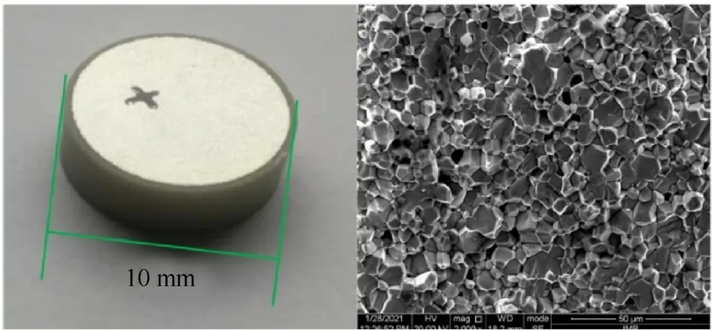
Fig.2.PZT-5h.
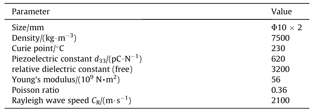
Table 2The parameters of PZT-5H.
2.3.Experimental and numerical simulation methods
2.3.1.Experimental method
The light-gas gun with a diameter of 16 mm was used as the loading device to carry out the experiment of the projectile hitting the aluminum alloy target at different speeds.The penetration and ignition reaction process of the projectile were recorded by the high speed motion analyzer(HSMA).The projectile velocity is 30,50 and 150 m/s respectively,and the thickness of the target is 4 mm.Fig.3 is a schematic diagram of the light-gas gun experimental system.

Table 1The parameters of the EED.

Fig.3.Schematic diagram of the light-gas gun experiment system.
The experimental test system mainly consists of a light-gas gun,a target chamber, the aluminum alloy target, a thin film pressure sensor(PVDF),a buffer device,HSMA and an oscilloscope.The lightgas gun loading system is composed of gas chamber, pressure gauge, gas supply bottle and gun tube.High pressure nitrogen is used as the power source to load the projectile to the set speed.When the projectile passes through the trigger plate, the trigger plate sends a trigger signal to trigger HSMA and oscilloscope synchronously, and the trigger time is recorded as T0.When the projectile impact the target, the PVDF outputs a signal T1.The impact velocity of the projectile is determined by the difference between T0and T1and the distance from the trigger to the target.
In the experiment, the maximum sampling frequency of the oscilloscope is 5 G/s.The HSMA used is PCO.dimax HS type produced by German PCO company, with a maximum resolution of 1000 × 1000 dpi, pixel size 11 × 11 μm2with a maximum frame rate of 180,000 fps.In order to get a clear impact process, a stroboscopic light source is used to record it.
2.3.2.Finite element analyze (FEA) method
The impact process of the projectile on the target is of high dynamic and transient response, and the self-powered ignition system in the projectile is in a closed state, so it is difficult to observe the dynamic electromechanical response of the PZT in real time.In order to further analyze the impact ignition process, the FEA method was used to analyze the impact process.The finite element model of projectile and target are established by Hypermesh software,and the relevant parameters are consistent with the experiment.The material parameters and impact velocity were set,and ABAQUS software was used to calculate the process of the projectile and target.Fig.4 is the finite element model of the projectile and target.
The projectile body is composed of the shell, Al/PTFE powder equivalent and impact igniter (including mass block, PZT, diaphragm and insulating layer).The shell and diaphragm are made of 45#steel.The target is homogeneous 6061 aluminum alloy,and its material parameters can be easily found in the literature.Mesh refinement was carried out for the area with the center side length of the target of 25 mm,and the seed density was 0.2 mm.Contact sets of all elements were set and FEA was carried out for the process of penetrating the target with ABAQUS/Explicit dynamics module.
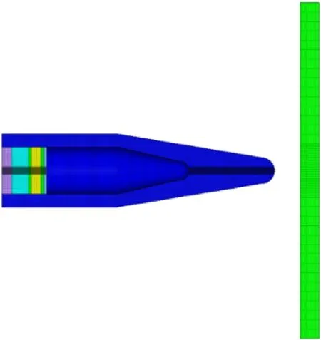
Fig.4.Finite element model of the projectile and target.
In the FEA process, the constitutive relationship of PZT in ABAQUS software is linear, and the existing constitutive model cannot accurately describe the dynamic mechanical properties of PZT.ABAQUS provides VUMAT subprogram interface for simulation in this case to adapt to different simulation requirements.Therefore,the dynamic mechanical characteristic experiment of PZT is carried out first,and the corresponding damage constitutive model is built according to the material mechanical behavior characteristics reflected in the experiment.The dynamic behavior of the material is combined with the penetration main program in the form of subprogram to explore the dynamic process of PZT in the process of the projectile hitting the target.
3.Dynamic damage constitutive model of PZT considering crack propagation
3.1.Dynamic electromechanical response of PZT
Based on the SHPB system and the transient electrical output measurement system, the characterization experiment of the electromechanical response of PZT-5H under different strain rates was carried out.
The setup of the experimental system is shown in Fig.5.The diameter of all the bars in the experiment is 15.5 mm and the bars are made of steel.The impact bar used to generate the initial wave is 200 mm in length and the incident bar and transmission bar for stress wave transfer are 1200 mm.As the piezoelectric ceramic is a brittle material,in order to delay the rise time of the load waveform as much as possible,a red copper waveform shaper with a diameter of 5 mm and a thickness of 1 mm is added at the end of the incident bar to further ensure the stress uniformity during the loading process.The pulse signal generated by the laser velocimeter is used to synchronize the start signal of the trigger.The synchronous trigger signal ensures the consistency of stress/strain, HSMA and output voltage.
The PZT-5H was loaded at four strain rates, and the experimental results with good repeatability were obtained at least three times for each strain rate.
The data of incident wave εi(t), transmitted wave εt(t), and reflected wave εr(t) are obtained by experiment and the three-wave method is used in the experimental data processing.The engineering strain rate ˙ε(t), strain ε(t), and stress σ(t) of the sample is calculated by
where C0,E,and A0is the elastic wave velocity,the elastic modulus,and the cross-section area of the incident bar;lsand Asis the length and the cross-section area of the sample; here, ls= 5 mm;As= 154 mm2.
High voltage differential probe(RIGOL,RP1100D,6.5 kV)is used to measure the output voltage at both ends of PZT-5H,and Eq.(4)is used to calculate the electric displacement (D) of the material.
where C is the equivalent capacitance of PZT,and its value is 1.5 nF;U is the measured voltage.
In the experiment with good repetition rate,the velocity of the impact bar is 1.5, 3.7 and 6.5 m/s, respectively, and the strain rate range is 200-900 s-1.The stress-strain curves of the samples under different strain rates are shown in Fig.6,and the samples after the experiment are recovered.

Fig.5.SHPB system.

Fig.6.Stress-strain curves of PZT-5H under different strain rates: (a) Original signal; (b) Results obtained by three wave method.
The experimental results show that the maximum yield stress of PZT-5H increases with the strain rate, and the fracture strength increases with the strain rate, which is consistent with the conclusion of Wang S [30].The samples after the experiment are recovered, as shown in Fig.6(b).It is obvious that the damage degree increases with the strain rate.When the strain rate is at a low level, PZT-5H has no obvious damage and fracture behavior in the range of 46 MPa;When the strain rate is 330 s-1,the sample breaks into three parts within the range of 120 MPa, and the breaking strength is about 110 MPa; With the further increase of the strain rate (impact stress), the sample is broken into a plurality of small fragments or debris at 246 MPa.
The port morphology of the recovered sample was analyzed by scanning electron microscope (SEM), and the grain size was counted as shown in Fig.7.From the SEM image and statistical results(Fig.7(b)),it can be seen that the grain shape is mostly rock sugar polyhedron, and the average grain diameter is 5-15 μm.At the same time,there are many original defects between the grains,and the diameter range of spherical like defects is 5-8 μm.The fracture morphology is typical intergranular fracture,with smooth grain surface and relatively flat fracture surface.These defects will appear stress concentration under the action of stress wave,resulting in the tensile stress between cracks being greater than the intergranular adhesive force and finally forming cracks,which will expand to the weak position with the continuous loading of stress[7], as shown in Fig.7(c).
Fig.8 shows the electrical output characteristics of PZT-5H under different strain rates.The open-circuit output peak voltage of PZT-5H under different strain rates is 1217, 3167 and 4486 V respectively, as shown in Fig.8(a).When the strain rate is 330 or 810 s-1, the material breaks, resulting in a huge fluctuation of the output voltage due to electrical breakdown.Fig.8(b)-(d)shows the σ and D time history curves of PZT-5H under different strain rates.Obviously, σ and D have a good correspondence when the strain rate is 210 s-1.When the material breaks at a higher strain rate,σ and D maintain a linear relationship before fracture.The ratio of D and σ is piezoelectric coefficient,d33,and the experimental result is about 750 pC/N(as shown in Fig.8(e)),which is different from the value 620 pC/N provided in Table 2, because that is measured at lower stress and strain rates.The effect of strain rate on the piezoelectric coefficient may be caused by the difference in the switching time of the internal electric domain and the domain change barrier in the PZT ceramic.Previous research [11] shows that the loading time is particularly important for domain switching when stress acts on PZT ceramic.Compared with the quasistatic state, the stress greatly increases in a short time, making it difficult for some domains with large angle to the polarization direction to switch.Therefore,the dynamic piezoelectric coefficient is lower than that of quasi-static conpression.For a more detailed explanation, please refer to our previous work [11].
In the process of crack formation and evolution, discharge and electric breakdown may occur in the material,thus causing charge leakage,as shown in Fig.8(f).The D of PZT under different stresses can be predicted by the following formula:
When dynamic d33=750 pC/N,the D calculated by Eq.(5)using the stress date is called theoretical D and represented by DT-xxx(xx is marked strain rate).Correspondingly, the real value of D is represented by DA-xxxIf the effect of strain rate on piezoelectric coefficient is ignored, the leakage D is 0.027 C/m2when ˙ε = 330 s-1,and peak DA-330decreases by 48%compared with DT-330,while this value reaches 417% when ˙ε = 810 s-1.From the perspective of charge, the loss of charge due to fracture at the two loading strain rates is 4.158 μC and 30.5 μC.These energies can activate any EEP in a short time.Since the output voltage of PZT is unstable after fracture, it is still considered that D and σ satisfy a linear relationship when establishing the dynamic electromechanical relationship of the material.
3.2.Damage constitutive model based on viscoelastic constitutive
Under compression, the decrease of the macroscopic bearing capacity of brittle materials is mainly caused by the nucleation and propagation of micro cracks.Therefore, the description of crack propagation in the global coordinate system on the basis of microstructure can theoretically explain the nonlinear characteristics of material stress-strain.As shown in Fig.9, the microstructure of PZT-5H was treated equivalently, and then the typical microcrack propagation process was analyzed.
In the equivalent model, σxand σyact on the two directions of the equivalent element respectively.The initial crack length is assumed to be 2a and the extended length at both ends is b.The stress on the crack surface is σx’and σx’y’, and the crack angle is φ
Through transformation of coordinates,σx’and σx’y’are
Let f be the coefficient of friction,the net stress τ leading to the slippage of the crack surface is
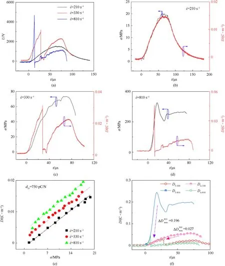
Fig.8.Electromechanical response of PZT at different strain rates:(a)Output voltage time history curves;(b)-(d)σ and D time history curves;(e)Relationship between σ and D;(f)D leakage caused by fracture.
Ignoring the weak interaction between cracks, the stress concentration factor of the type-I crack tip under biaxial compression is expressed as
with b = b* = 0.27a.
Crack density N is an important parameter that affects the development of microscopic damage.According to Grady's research[31], N can be expressed as
where k and m are both uncertainty parameters about cracks.
Under biaxial load, elastic deformation and crack deformation together constitute the total element deformation
where μ is the Poisson ratio, and Sxyis a flexibility tensor of crack deformation.Hence, the problem is focused on solving out this flexibility tensor.
The derivation of constitutive model is based on energy conservation during crack development.The external work W is all converted into the elastic energy of the crack deformation Uesand the friction energy of the crack Wcf.
W can be calculated by the following equation:
where Aerepresents the calculated area.
The energy release rate G is obtained by differentiating the crack propagation length with the energy released at the crack tip.
In type-I cracks, the relationship between G and KIis
There are two tips of the crack(as show in Fig.9),so Uescan be calculated as the following equation
By substituting Eq.(9) into Eq.(17),
On the other hand,Wcfcan be calculated from the slip force and the slip length of the crack surface (L),
I have been assured, said the Cat, that you have the gift of being able to change yourself into all sorts of creatures you have a mind to;33 you can, for example, transform yourself into a lion, or elephant, and the like.
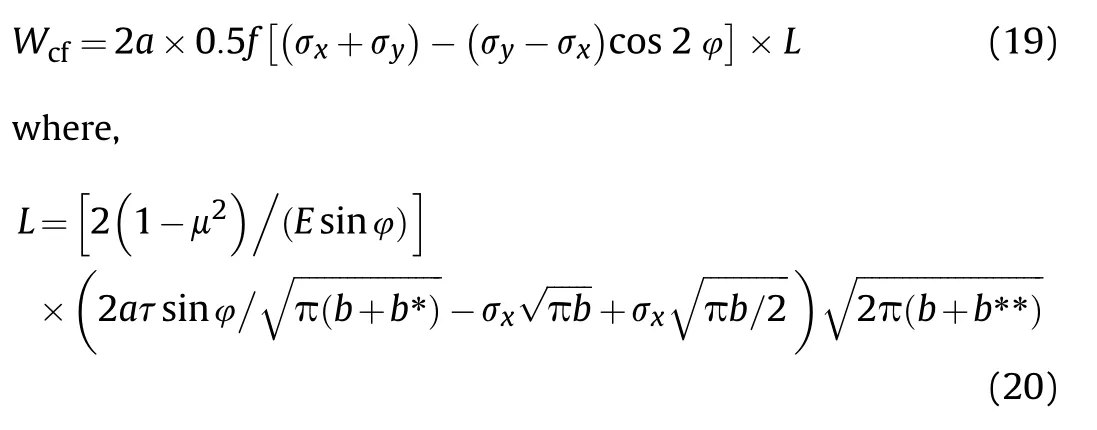
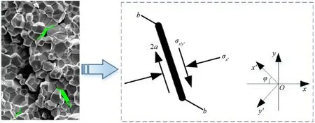
Fig.9.Internal crack nucleation and evolution process of PZT-5H.
To ensure the correctness of L under small tensile length,b**= 0.083a.
According to Eqs.(19) and (20),
By Eq.(12),the flexibility tensors Sxx,Sxyand Syycaused by cracks can be calculated by combining Eqs.(13), (18) and (21).
From Eqs.(10),(11)and(22)-(24),Dam is used to represent the decrease of macroscopic bearing capacity due to the evolution of micro-cracks.Under uniaxial compression, Dam can be expressed as Refs.[32,33].
Further, combined with the viscoelastic dynamic piezoelectric equation based on ZWT yield criterion[11],a PZT dynamic damage constitutive model considering crack growth under impact(D-ZWT constitutive)is constructed as follows:
3.3.Determination of model parameters
Next,the parameters of the constructed constitutive model will be determined.Chen H[34] et al.showed that the KIof PZT in the polarization direction was about 1 MPa∙m0.5, and the KIDwas 10 times of KI.Ignoring the dispersion of φ,it is taken to be π/4 as the statistical mean.The length of the initial defect is set as 5 μm as shown in Fig.7.Damage thresholds (Dth), k, m, E0, E1and θ1were determined by fitting according to the experimental results(Fig.6(b)).Fig.10 is a comparison between fitting and experimental results.Table 3 shows the fitting results of model parameters.

Table 3Fitting parameters of the model.
4.Analysis of experimental and FEA results of projectile impact ignition
4.1.Programming of the constitutive model
Considering the finite deformation,the ZWT model needs to be extended to a three-dimensional form,
where Sklis Kirchhoff stress tensor; Eijis the Green strain tensor.
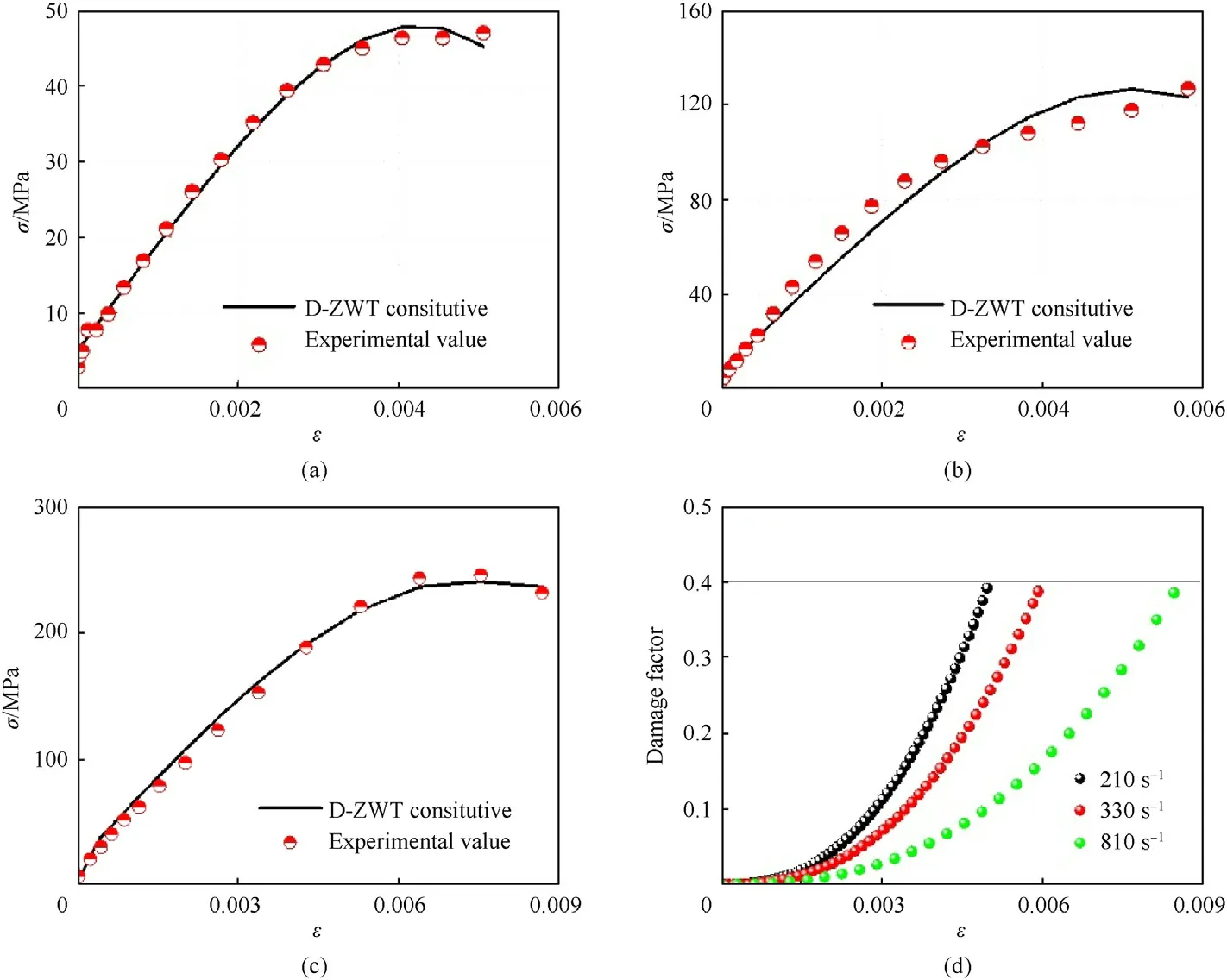
Fig.10.Comparison between fitting and experimental results: (a) 210 s-1; (b) 330 s-1; (c) 810 s-1; (d) damage evolution.
The incremental form of Eq.(27) is [35].
Kirchhoff stress is transformed into Cauchy stress,
Assuming that the damage evolution process under the threedimensional stress is isotropic, the form of Ref.[36] is adopted
It can be seen from Eq.(25) that Dam is actually a binary function of material strain and strain rate in the process of damage evolution when other parameters are determined.By combination with Eq.(30),Dam(εe,˙εe)is used to reflect the evolution process of materials under different strains and strain rates.Therefore, the damage change in two adjacent moments can be expressed as
At the same time,according to the irreversibility of the damage process,it is necessary to judge the positive and negative values of Eq.(31).When ΔDam(t+Δt)>0, its value remains unchanged, but whenΔDam(t+Δt)≤0, take ΔDam(t+Δt) = 0.The incremental form of damage factor is expressed as
In FEA,the default Dthin the system is 1,but in fact,Dthis largely related to the material itself and the selection of the damage constitutive model.In order to better reflect the failure behavior of the material in the bearing capacity of the element, the damage correction coefficient h is introduced.In the process of FEA, the relationship between the corrected damage value hDam of the element and 1 should be judged in time.When hDam ≥1, the element will be invalid and deleted to ensure the convergence of calculation.
If the influence of damage is taken into account in Kirchhoff stress tensor, then
The increment of stress tensor considering damage is expressed as
Under the assumption that the material is incompressible, ρ/ρ0=1, the Kirchhoff stress is converted according to Eq.(29)
The incremental form of the electromechanical relationship is
The ABAQUS user material VUMAT subroutine was developed to predict the dynamic electromechanical response of PZT using the D-ZWT model.Specific details of program development can be found in Refs.[11,35].Based on the developed VUMAT subroutine,the FEA of the ignition performance of the missile borne selfpowered igniter is realized by using the material parameters obtained from the SHPB experiment (as shown in Table 3).
4.2.Result analysis
Fig.11 shows the process of a projectile carrying a piezoelectric igniter impacting a target under the experimental conditions shown in Fig.3.When the impact speed is 30 m/s,the projectile will bounce off after impacting the target, and the igniter will not be activated.Indicating that the electric charge released by PZT-5H is not enough to ignite the EED when the projectile velocity is low.When the speed is 50 m/s,the projectile rebounds after impacting the target, causing little damage to the target and failing to penetrate the target plate.It can be seen from Figs.11(2a)-(2e)that the projectile starts to spray flame outwards after the contact between the projectile and the target plate is about 350 μs.Considering the propagation process of stress wave during the contact between the projectile and the target, the reaction delay time is about 300 μs.After the ignition is completed, the powder in the projectile will react continuously, and the duration of the flame is more than 700 μs.When the velocity of the projectile is 150 m/s,the projectile is embedded into the target.During the penetration process, the igniter works and ignites the powder in the projectile.The delay time from the projectile hitting the target to the gas ejected from the projectile is about 250 μs.The higher the impact speed, the shorter the ignition delay time.
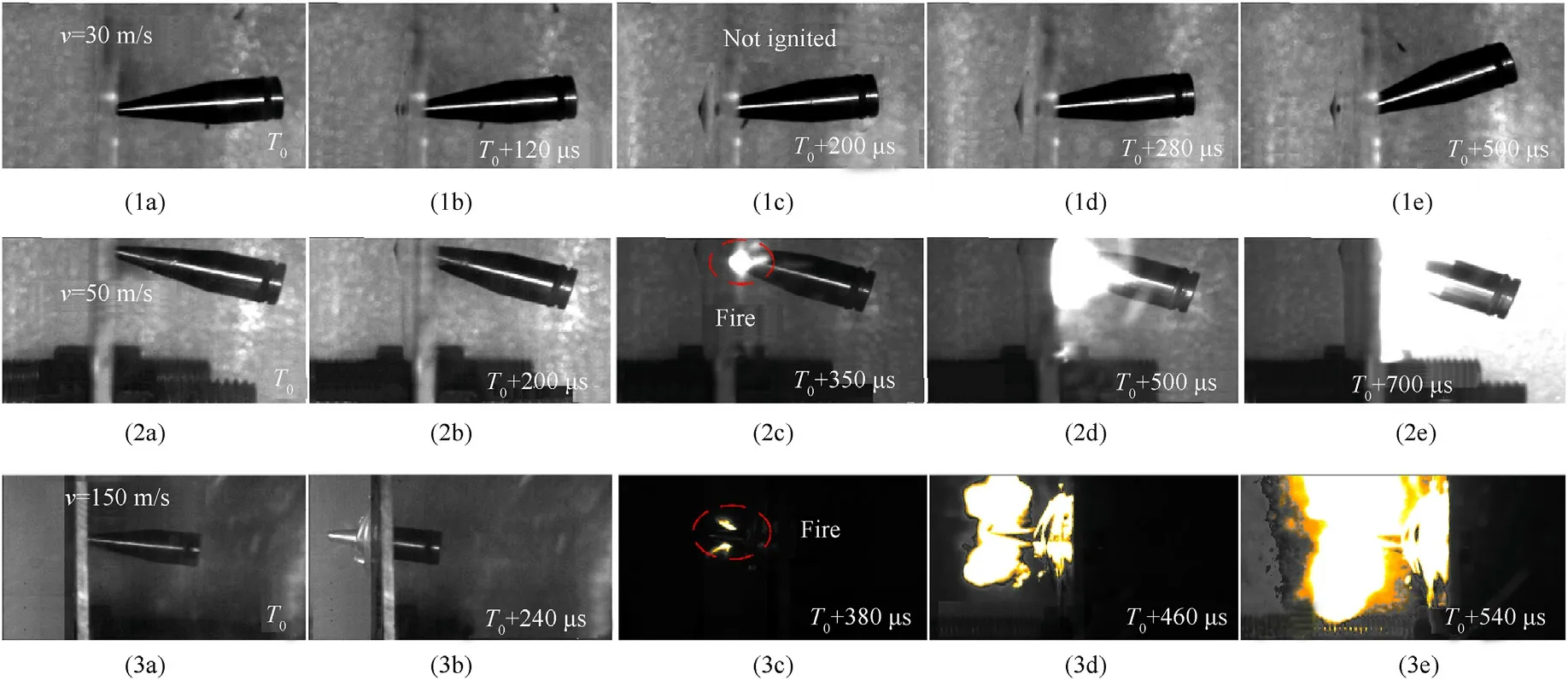
Fig.11.Ignition process of projectile penetrating target with piezoelectric igniter.
Although the experimental results confirm the ignition reliability of the impact igniter, there is no accurate measurement result to evaluate the electrical output performance of the PZT in the projectile.Therefore, the PZT dynamic damage constitutive material subroutine considering crack propagation was used to calculate the mechanical and electrical output responses of PZT-5H under the same experimental conditions in ABAQUS software.The finite element models of the projectile and target have been given in Fig.4.Fig.12 shows a stress nephogram of projectile impacting the target at different speeds.
It can be seen from Fig.12 that the projectile rebounds after colliding with the target and fails to penetrate the target when the velocity is 30 m/s.When the speed is 50 m/s,the target is deformed,but still not penetrated.When the speed is increased to 150 m/s,the target is penetrated and the projectile is embedded in the target.The numerical simulation results are completely consistent with the experimental results shown in Fig.11.

Fig.12.Stress nephogram of projectile impacting target.

Fig.13.Stress nephogram of PZT-5H during the impact.
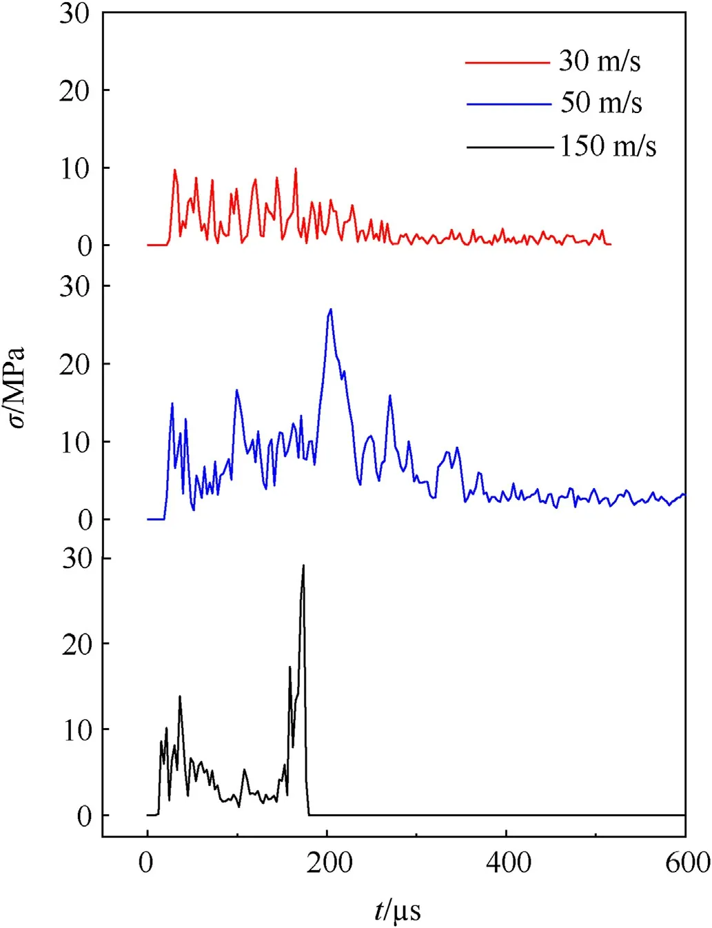
Fig.14.Stress time history curves of PZT-5H in the process of projectile penetrating target.
When the projectile impact the target at different speeds, the state of PZT-5H in the projectile is shown in Fig.13.When the speed is low, the piezoelectric material is not obviously damaged, and when the speed is 150 m/s, the material is broken.The corresponding stress time history curve is shown in Fig.14.The target is slightly deformed with the projectile speed at 30 m/s and 50 m/s.In those process, the maximum stress (σmax) of PZT is 9.8 MPa and 27 MPa,respectively.The PZT will fracture or even break when the stress exceeds its yield stress.When the speed is increased to 150 m/s, the projectile sticks to the target and does not penetrate.According to the previous model derivation, the damage factor during the numerical simulation is affected by the combined effect of strain and strain rate.In the process of the projectile hitting the target plate,the damage factor rises rapidly and quickly reaches the destruction threshold.The program will delete these grids,and the deleted grids will no longer bear the impact effect, resulting in a maximum stress of only 29 MPa.In fact,according to the damage of the sample during the impact and the actual fracture morphology of the sample after impact,it can be seen that the stress of PZT-5H is much greater than this value.
The output energy of PZT-5H can be calculated by the following equation:
During the ignition process, the change of resistance with temperature in EEP is ignored,and it is considered that the system is adiabatic in a very short time.Therefore,all the output energy of PZT is used to heat the resistance wire in the EED.According to the specific heat capacity (cw) and quality of the bridge wire (m1), the relationship between the temperature of the bridge wire T(t) and the output energy of PZT can be obtained by using the following equation:
where Tais the ambient temperature (300 K).T(t) is calculated by Eqs.(37) and (38), as shown in Fig.15.It is considered here that when T(t) reaches the activation temperature (588-636 K [11]) of lead 2, 4, 6-trinitroresorcinate (LTNR) around the resistance wire,the igniter is activated.

Fig.15.Change of T(t) with time under different impact conditions.
FEA results show that the maximum temperature of the bridge wire is 548 K when the projectile speed is 30 m/s,which does not reach the minimum ignition threshold of LTNR.Therefore, the projectile does not ignite.When the projectile speed is 50 m/s,T(t)rapidly rises to 800 K within 6 μs of the projectile target contact.It can be seen from Fig.15 that when the projectile speed exceeds 50 m/s,the output electric energy of PZT-5H may easily exceed the ignition threshold of LTNR,and T(t)maxmay even exceed 1200 K.In fact, when the bridge wire temperature exceeds the activation temperature of LTNR, the heat generated by the chemical reaction will quickly melt the bridge wire,so the temperature value greater than the activation threshold has no physical significance.
In addition, in the practical application process, the ignition performance of the self-powered activator depends not only on the speed of the projectile, but also on the type and size of the piezoelectric material,the weight of the mass block and the type of EED.
5.Conclusions
A PZT based impact igniter for small caliber projectiles was designed and fabricated.The experiment of small caliber projectile impacting aluminum alloy target was carried out to verify the reliability of the piezoelectric self-powered igniter.In order to find out the relationship between the electric output performance and the structural parameters of the igniter, A SHPB test was carried out.Combined with microscopic analysis, the mechanical and electrical responses of PZT-5H under different strain rates were studied, and a dynamic damage constitutive model of PZT considering crack propagation was established.Based on the established D-ZWT constitutive model subroutine,the FEA of projectile impact process was carried out.
The impact test and FEA results show that the designed missile borne self-powered igniter can stably ignite when the projectile speed is higher than 50 m/s.On this basis,the ignition threshold of the igniter can be flexibly controlled by adjusting geometric and physical parameters such as PZT parameters (model,size,number,connection mode, etc.), mass block parameters (density and size),and ignition tube model.In addition, in the actual engineering design of the igniter, the influence of service environment such as strain rate and ambient temperature on the electric output performance of PZT should be fully considered based on the research in this paper.On the premise of ensuring reliability and safety, the volume and mass of the igniter should be reduced as much as possible in combination with the actual service environment.
Data availability
The data that support the findings of this study are available from the corresponding author upon reasonable request.
Declaration of competing interest
The authors declare that they have no known competing financial interests or personal relationships that could have appeared to influence the work reported in this paper.
Acknowledgments
This research is supported by the National Natural Science Foundation of China (Grant No.12172232), and the project of Key Laboratory of Impact and Safety Engineering (Ningbo University,China), Ministry of Education (CJ202206).At the same time, this work was supported by the scientific research support plan of introducing high-level talents from Shenyang Ligong University.
- Defence Technology的其它文章
- The dynamic response and damage models of rebar reinforced polymer slabs subjected to contact and near-field explosions
- Study of the axial density/impedance gradient composite long rod hypervelocity penetration into a four-layer Q345 target
- Active learning accelerated Monte-Carlo simulation based on the modified K-nearest neighbors algorithm and its application to reliability estimations
- Dynamic compressive response of porcine muscle measured using a split Hopkinson bar system with a pair of PVDF force transducers
- Damage of a large-scale reinforced concrete wall caused by an explosively formed projectile (EFP)
- Air target recognition method against ISRJ for radio frequency proximity sensors using chaotic stream encryption

