
LSTM-DPPO based deep reinforcement learning controller for path following optimization of unmanned surface vehicle
2023-11-06 14:19:56XIAJiaweiZHUXufangLIUZhongandXIAQingtao
XIA Jiawei ,ZHU Xufang ,LIU Zhong ,and XIA Qingtao
1.School of Weaponry Engineering,Naval University of Engineering,Wuhan 430033,China;2.Qingdao Campus,Naval Aviation University,Qingdao 266041,China;3.School of Electronic Engineering,Naval University of Engineering,Wuhan 430033,China
Abstract: To solve the path following control problem for unmanned surface vehicles (USVs),a control method based on deep reinforcement learning (DRL) with long short-term memory(LSTM) networks is proposed.A distributed proximal policy optimization (DPPO) algorithm,which is a modified actor-criticbased type of reinforcement learning algorithm,is adapted to improve the controller performance in repeated trials.The LSTM network structure is introduced to solve the strong temporal correlation USV control problem.In addition,a specially designed path dataset,including straight and curved paths,is established to simulate various sailing scenarios so that the reinforcement learning controller can obtain as much handling experience as possible.Extensive numerical simulation results demonstrate that the proposed method has better control performance under missions involving complex maneuvers than trained with limited scenarios and can potentially be applied in practice.
Keywords: unmanned surface vehicle (USV),deep reinforcement learning (DRL),path following,path dataset,proximal policy optimization,long short-term memory (LSTM).
1.Introduction
As a small surface platform for operation,unmanned surface vehicles (USVs) offer several advantages such as low cost,high speed,intelligence,and no casualties.It has broad application prospects in military applications,scientific expeditions,commercial development,hydrographic surveys,search and rescue,relay communications,etc.[1].Motion control is the core of the techniques used for USV autonomous navigation,which can help a USV to smoothly complete the tasks.
USV path following has always been a popular but difficult topic in the relevant research fields.It is defined as the process in which a USV is driven by a control system without considering temporal constraints to depart from any initial position and reach the expected path while eventually arriving at the designated destination along with the path [2].A USV with no side thruster or perhaps with a side thruster fails during high-speed navigation,which is common in a typical underactuated system.This type of system is complex to some extent because the number of control inputs is lower than the number of degrees of freedom (DOF) to be controlled.
Many researchers have developed various control algorithms to address the path following needs of underactuated USV.The research methods for path following mainly include the Lyapunov direct method [3,4],feedback linearization [5],sliding mode control [6,7],the back-stepping method [8,9],active disturbance rejection control [10],robust control [11],and model predictive control [12,13].These conventional control methods often need to consider the prior knowledge of an USV dynamic model and cope with strong coupling,complexity,and uncertainty of the system.Reinforcement learning (RL) is the opposite of the feedback evaluation of optimal control theory since it is mainly based on valuation and can operate when the system model is unknown[14].Unlike optimal control theory,RL is based on evaluative,rather than being instructive;feedback comes in different forms,which may or may not include partial knowledge of the environment or the system.With the continuous progress in the field of artificial intelligence,RL has become an important branch of machine learning and made remarkable progress in the field of control and decision [15-18].
There have been plenty of attempts to implement deep RL (DRL) techniques in path following control for unmanned vehicles [19,20].Among them,the convergence performance of RL controller has received the most attention.Typically,path following controller is composed by a cascaded system of a guidance law and a low-level controller.One promising approach is to have DRL controller acting as both of them [21,22].DRL network output the speed and steering command according to the USV’s cross-track error and heading error relative to the desired path,as well as the kinematic parameters of the platform.Although the techniques to ensure the robustness to disturbances were adopted such as the Ornstein-Uhlenbeck process in control actions [23],the convergence of the DRL controller wasn’t strictly proved.The other approaches input DRL network with guidance law [24],such as line-of-sight (LOS) [25] and vector field guidance (VFG) [26],which do not impose complex proof of stability on the path following control.However,these studies were only verified in single cases or limited scenarios.
Although USV can effectively converge in the simulation with a DRL controller,as a black-box method,the lack of interpretability makes its security questioned.It is of vital importance to avoid catastrophic safety accidents in engineering practice.Hence,improving the security while ensuring convergence with the USV path following control is of great concern.
In order to bridge the aforementioned research gap,a path following method for underactuated USV with the feature of both convergency and security is proposed.Firstly,dynamics and kinematics models of USV are established,and then the LOS guidance law and USV motion states are combined as the DRL controller’s input.Inspired by training deep learning networks with massive data sets,the concept of data sets for path following is established,which allows a distributed stochastic sampling of the problem’s domain that enhances the generalization of the task at the cost of a larger training process.Furthermore,the long short-term memory-distributed proximal policy optimization (LSTM-DPPO) algorithm is designed to process large-scaling training work by distributed computing.In addition,considering that path following control is a strong time-relevant problem,the LSTM network layer is introduced in the neural network.The performance of the proposed method was evaluated using simulation experiments in various scenarios.The analysis results demonstrate that our method is effective for path following control of USVs.
Salient contributions in this paper can be summarized as follows.
(i) The concept of path dataset is proposed for the first time by generating a variety of possible path combinations to cover the USV sailing scenarios,which helps the DRL controller adaptable to the critical situation.
(ii) A distributed proximal policy optimization reinforcement learning method with the LSTM layer is designed to meet the requirements of extensive training and time-relevant control.
The rest of this paper is organized as follows.Section 2 presents the USV dynamics model,guidance method,and reward functions design.Section 3 introduces the path dataset and simulation environment.Section 4 gives theoretical background and technical implementation details of the LSTM-DPPO method.Section 5 discusses the validation and comparative analysis of the proposed method.Finally,Section 6 presents the main conclusions and potential for future work.
2.USV path following
Fig.1 presents the USV path-following control process.The process can be regarded as the transfer of data between three modules,including the USV dynamic model,USV virtual environment,and controller.A USV dynamic model can use the control input to estimate the state at the next moment and send kinematics parameters to the virtual environment.Subsequently,the virtual environment determines the position of the USV on the map in a real-time manner and calculates the guidance parameters based on the mission path.
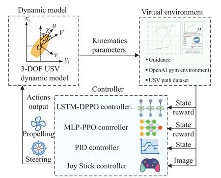
Fig.1 Diagram of a USV path following control
Depending on the principles of feedback control used,controllers require different inputs.For instance,RL controllers such as LSTM-DPPO or multilayer perceptron version of proximal policy optimization (MLP-PPO)mainly require state and reward input,whereas conventional control methods like proportion-integral-derivative(PID) controllers only need state data.Thanks to the graphical simulation environment of OpenAI,a joystick controller can compete with an artificial intelligence (AI)algorithm.In this case,the controller only requires images as input,and a closed-loop of feedback exists.This process is similar to someone playing a video game.
The dynamic process of USV path following requires the use of a USV dynamic model to calculate the response under a given control.Meanwhile,a guidance system should be designed to determine the expected heading to evaluate whether the USV effectively follows the desired route.The rest of this section provides detailed information about the components of the USV path following system.
2.1 USV dynamic model
Path following by a USV focuses on motion in a two dimensional (2D) plane.Therefore,this paper ignores the concepts of heave,roll,and pitch but uses the 3-DOF kinematic model [25],which can not only address the problems of accuracy and network generalization during the path following in a plane but also meet the requirements for providing a convenient calculation method.
The coordinate system used in this work is shown in Fig.2.

Fig.2 Coordinate system of a USV
In Fig.2,XandYare the East and North direction;uandvstand for surge and sway;ψ,β,and χ denote heading angle,side slip angle,and course angle respectively;USV position can be described as η=[x,y,ψ]T,and speed asv=[u,v,r]T.The 3-DOF USV kinematic model can be described as
whereR(η) is a rotation matrix from the body-fixed frame to the Earth-fixed inertial frame.
The horizontal planar dynamic motion equation of the USV can be expressed as
whereMis the mass matrix,C(v) is the Coriolis and centripetal matrix,D(v) denotes the damping matrix.τc=[τu,0,τr]Tdenotes the control inputs,τuis the surge force,τris the yaw moment.τe=[τeu,τev,τer]Tis the environmental forces due to wind,waves,and ocean currents.τeu,τev,τerdenote the disturbances of the surge,sway,and yaw,respectively.
Equation (3) can be simplified as
2.2 Guidance
The guidance module aims to guide the USV along the desired path by calculating the current position of the USV and defining its relationship with the given path.As shown in Fig.3,the USV virtual environment module can upload the desired path taskP(ω) as needed and the guidance sub-module calculates the desired course angle χd(t) and cross-track errorye(t) using the LOS guidance method.As for speed control,this paper focuses on path following,which is different from trajectory tracking and does not need to take temporal specification into account[27].Therefore,the guidance module does not include speed interference.In our opinion,USV speed control could be directly achieved by the controller network with inputs such as speed errorue(t)=ud(t)-u(t),heading error ψe(t),and cross-track errorye(t),which will be detailed in the subsequent sections.

Fig.3 Diagram of guidance module for a RL-based controller
LOS is a type of classical and effective navigation algorithm that reflects the helmsman’s specific behavior in the accurate control of vessel navigation.A LOS vector is the line connecting a point mapped as seen from the current position of a vessel onto the tangent line of the desired path from that point to the current position of the vessel [28].By keeping the vessel’s resultant speed in alignment with LOS vector,the vessel is guided to approach the desired path.LOS guidance is independent of dynamics control,does not rely on any mathematical model,and needs few designed parameters.Moreover,it is insensitive to high-frequency white noise and uses the desired path and the vessel’s real-time position only to determine the desired heading angle.In this way,the desired heading angle can be calculated efficiently in realtime.
This paper uses a LOS guidance algorithm based on the look-ahead distance to calculate the desired heading angle.The guidance principles are as shown in Fig.4.

Fig.4 LOS guidance based on the look-ahead distance
The LOS guidance algorithm is defined as
where χd(t) is desired course angle;P(t) is the actual position of the USV;(xd(ω),yd(ω)) is desired position of the USV;ψp(ω) denotes the angle formed by the tangential line of the desired position on the desired course andX-axis;Δ is the look-ahead distance;Plos(t) is a virtual guidance point;ye(t) is the cross-track error,such as the deviation of the current position of USV from the desired course.Therefore,the desired heading angle ψd(t) is
The heading angle error is
LOS guidance can be used for both straight and curved paths.Woo et al.[29] analyzed the switching principles of LOS guidance for a straight path.The switching principles were improved to achieve a smooth switch between straight and curved paths based on this guidance.If the USV mission path consists of several linked subpaths of various lengths and shapes such as straight lines and arcs,the USV path following task follows the adjacent straight or curved sub-paths one by one.Moreover,it is assumed that this process is irreversible.In other words,the task does not return to the previous sub-path following even if USV turns back to the starting point.
It is assumed that from the starting point,theith subpath Pathistarts at ωi-1(xi-1,yi-1) and ends at ωi(xi,yi),i∈N∗.When Pathiis straight,the USV will follow the straight path Pathi.At any point,the desired course angle could be displayed in a vector field,as shown in Fig.5.
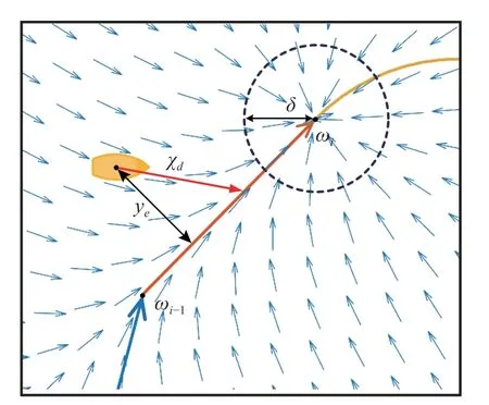
Fig.5 Diagram of a straight LOS guidance vector field
Equation (5) can be used to calculate the desired course angle χdand the corresponding virtual guidance pointPlos.When the USV enters a circle with the origin ωiand a radius δ,it is believed that the task of following the current sub-path is completed,and it switches to the state of following the next sub-path.To ensure that the USV can be guided to the proximity of where the sub-path ends under extreme conditions,it is therefore defined that,if the virtual guidance pointPlosis on an extension of a line segment ωi-1ωi,the virtual guidance pointPlosof the USV will be fixed at the position where the sub-path ends ωi.
When the USV follows a curved path,guidance principles are slightly different based on the sector in which the USV travels.As shown in Fig.6,if the USV follows the curved path Pathi+1,the desired course angle at any point can be presented vividly in the vector field.LetOcbe the origin of the arcs that the sector formed by ∠ωiOcωi+1is defined as Sector B,while the remaining area is divided equally into Sector A and Sector C with the originOc.Normally,the USV is in the normal state of path following when it is in Sector B.Considering that RL control could not be stable at the initial stage of learning,all possibilities must be taken into account to ensure the correct guidance for the USV at any position.
The policy for different conditions is as follows: when the USV is in Sector A,LOS guidance is implemented to guide the USV along a sub-path pathi;when the USV is in Sector B and the virtual guidance pointPlosis in Sector B,LOS guidance is conducted to guide the USV along the current sub-path pathi+1;when USV is in Sector B and virtual guidance pointPlosenters Sector C,a virtual guidance point will be fixed at the position where the subpath ends ωi+1;when USV is in Sector C,the virtual guidance pointPloswill be also fixed at ωi+1.
The guidance module will output the heading angle error ψe(t) and cross-track errorye(t) .Moreover,ψe(t)can be calculated with (7),while the value ofye(t) could be calculated considering the geometrical relationship at any time.
When the USV follows a straight path or is in Sector A or Sector C of a curved path,ye(t) is the Euclidean distance from the USV to the straight line.
When the USV follows a curved path and is in Sector B,let the radius of the arc ber,and the originOc(xo,yo),so thatye(t) is the shortest Euclidean distance from USV to the arc:
2.3 Reward function
The reward function defines the target in RL [30].In each time step,the environment assesses the performance of the USV in the execution of the path following task,and give a reward output.The objective of the RL controller is to maximize the total reward for the long term.Hence,the reward function requires clearly defines the quality of the USV state,and plays a significant role in RL.On this basis,several independent performance indices have been designed,including heading reward,distance reward,and speed reward,to measure the effect of path following,respectively.Moreover,these indices are weighted according to actual needs to achieve comprehensive assessment.
Index 1Heading reward.To make the USV move forward in the correct direction,a maximum heading reward is obtained when the absolute value of the USV heading angle error |ψe| is 0,but the heading reward should decrease rapidly when |ψe| deviates from 0.The heading reward is defined as
where∈(-1,1],andkψis an adjustment coefficient used to determine the steepness of the reward at the peak.
Index 2Distance reward.To make the USV move along a given path,a distance rewardis proposed.A distance reward is defined as
Index 3Speed reward.To ensure the movement of the USV at the desired speed,a speed rewardis proposed as
where∈(-1,1] andconsists ofru1andru2,respectively.pis a weight coefficient andp∈[0,1].ku1andku2are the adjustment coefficients ofru1andru2,respectively.Among them,ru1is used to constrain the speed of the USV anducosψeinru2indicates the projection of the USV speed onto the desired course;the speed can reach the maximum only if the projection speed on the desired course is identical to the desired speed.
Composite indexReward function.In summary,the final reward expression is given as
3.USV path dataset
As an important part of RL,environment modeling is the simulation of the environment response mode [30].Nevertheless,researchers often do not conduct extensive environment modeling because complex and varying tasks exist in path planning.Studies related to RL control with marine vessels normally focus on the simple paths[22,29].Moreover,these test scenarios are generally mentioned in parts of simulations in the papers.Researchers placed an agent in a fixed scenario and then trained an RL controller from scratch (the RL controller was trained separately for each test scenario).The control errors at different stages of training were compared to verify the effectiveness of the RL algorithm [31].But an RL controlled trained in a single scenario may easily cause over-fitting and lead to network degeneration.For engineering applications,such limited navigation experience for DRL controller is far from enough.When facing extreme scenarios,the controller network’s output is likely to be unpredictable without enough training experience.It will cause uncertainty and hidden safety problems in the engineering applications
There has to be a balance between the performance and the generalization of the environment.When training to a few particular environment variations,the deep policy tends to overfit and loses the ability to generalize to different paths.Therefore,it must be mentioned that the random generation of paths,allows a distributed stochastic sampling of the problem’s domain that enhances the generalization of the task at the cost of a larger training process.A path dataset was constructed to satisfy the needs of multiple tasks.
When considering the needs of a USV RL control,it is necessary to construct a variety of USV mission paths,which must cover as many path scenarios as possible and serve as a baseline for comparing the performance of different algorithms.Therefore,two types of path datasets were constructed,the random path dataset and the standard path dataset.
First,the random path dataset plays the role of providing all kinds of task scenarios for RL controller training,which meet the following requirements:
(i) It can be generated quickly with an automation script.
(ii) Paths should contain straight lines and curves simultaneously,and the boundary between paths should be continuous.
(iii) Paths must not go beyond the given boundary and be easy to display visually.
Second,the standard path dataset must meet the following requirements:
(i) The path should be typical and cover a variety of conditions.
(ii) The dataset should contain a single straight line,curved and mixed paths,and facilitate the quantitative and comparative control analysis of diverse paths.
A flowchart of the automated path generation algorithm designed in this paper is shown in Fig.7 and Fig.8,and Fig.9 shows the instance diagram of the random path dataset.

Fig.7 Flowchart for generating a random path
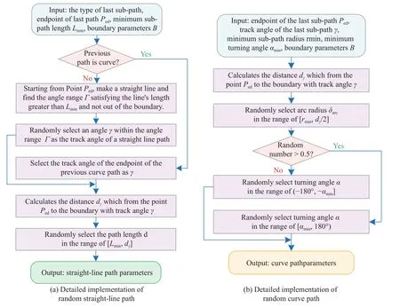
Fig.8 Detailed implementation of the random straight-line path and random curve path

Fig.9 Instance diagram of random path dataset
To meet the above requirements,14 different mission paths are designed (Fig.10),including seven polygonal paths (paths A-G),three curved paths (paths H-J) and four mixed paths (paths K-N).Each polygonal path was comprised of sub-paths of equal length,which are connected with a fixed steering angle.Among them,Path G is a back-and-forth path on a straight line.A curved path is formed by an arc or spiral,while a mixed path is composed of straight lines and arcs connected alternately.Based on this,paths were mirrored to form 28 types of horizontally symmetrical routes,eventually measuring an RL controller’s performance more comprehensively.
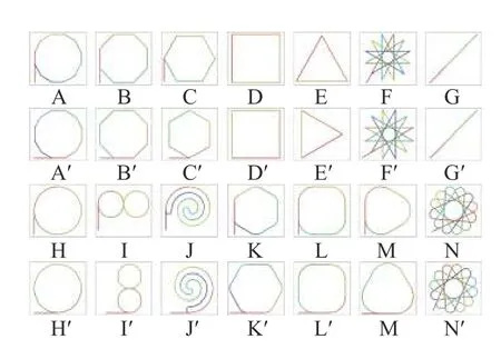
Fig.10 Dataset of 28 standard paths
To thoroughly test each type of path,all standard paths were set to depart from the lower-left corner along a start line in red and then repeat the closed path many times until the accumulated distance reached the preset mileage of each path.The average performance index of each control algorithm with the same reference path was compared to objectively and comprehensively evaluate these algorithms.
Fig.11 details the composition and interaction of modules under the step function in the Gym environment customized in this paper.

Fig.11 Composition and interaction of modules under a step function in a customized Gym environment
4.DRL based controller
As an important part of machine learning,reinforcement learning means an agent learns the action policy needed to fulfill the mission through continuous interaction with the environment.While performing a mission,the agent interacts with the environment to generate a new state,while the environment grants a reward.An RL algorithm uses an action policy to interact with the environment,generate a reward,and then apply the reward in modifying the action policy.After several iterations,the agent will learn the action policy needed to complete the mission.
The traditional RL approach is often limited to a finite and discrete action space and sample space.This makes it difficult to process more complex missions close to the actual conditions,often involving the continuous and high-dimensional state spaces and action spaces.DRL combines RL with deep learning capability to process high-dimension data,while deep Q networks (DQN) must be the first successful product of such a combination [31].Scholars have extensively studied the RL approach in recent years and proposed more and newer DRL methods such as asynchronous advantage actor-critic (A3C) [32],deep deterministic policy gradient (DDPG) [33],and PPO[34].
USV path following requires considering paths of complex shapes;the entire process of guidance is highly sequential and involves interconnected trajectories.Therefore,this paper combines the PPO framework [35]with the LSTM with a strong ability to process temporal data and then proposes a LSTM-DPPO based path planning algorithm,which allowed several environments to gather the experience at the same time by parallel central processing unit (CPU) process,and the training work is divided among the GPUs.
4.1 PPO Algorithm
PPO is a model-free,on-policy,actor-critic,policy-based method.As an improved algorithm,it originated from a trust region policy optimization (TRPO) algorithm [36].The standard solution of a TRPO algorithm requires an enormous amount of calculation,but PPO is a first-order approach and simplifies the optimization process,which reduces the calculation effort considerably and achieves a good effect.
In the process of training,the state of the agent at the timetis denoted byst.PPO uses stochastic policy,so that the policy π could be modeled as π(a|s);that is,the probability distribution ofaat the states.In this paper,π is the LSTM controller network,whose parameter is denoted by θ.The controller network πθinput the state of the agentstand outputs a gaussian probability distribution of actions.Sampling is further conducted to obtainat.Meanwhile,the environment will grant a reward based onstandat,that is,rt+1(st,at).The objective of RL is to find the optimal policy π∗to maximize the accumulated discount rewardRtas
where γ is a discount factor and γ ∈[0,1].
The policy π is evaluated by two pecspective,the statevalue functionVπ(s) and action-value functionQπ(s,a).Vπ(s) is the expected return when starting insand following π thereafter.Meanwhile,Qπ(s,a) is the expected return starting froms,taking the actiona,and thereafter following policy π:
An advantage functionAπ(s,a)can be used to determine the advantage achieved by choosing an actionaat the stateswhen compared with other actions.If the actionais a better choice.
The PPO algorithm offers a truncated version of generalized advantage estimation [37] to estimate an advantage function,which could significantly reduce the variance while maintaining a tolerable level of bias.Therefore,is defined as the estimator of the advantage function at the timestept,andTrepresents the number of time steps taken continuously under the policy π in an episode (Tis much shorter than the episode).The expression ofis as follows:
A policy gradient algorithm is an RL algorithm for policy-based search.It estimates a policy gradient and applies it in a stochastic gradient ascent.Meanwhile,LPG(θ) represents the policy gradient loss,andserves as empirically obtained estimates of the expectation.The expression is as follows:
However,empirically,the gradient obtained by using the expression above is likely to lead to too large policy updates.By optimizing the surrogate objective functionL(θ),TRPO could constrain the amplitude of the policy update.
On this basis,PPO includes two simpler realizations,i.e.,clipped surrogate objective and adaptive KL penalty coefficient.The former has a better effect,so that method is employed in this paper.Its objective function isLCLIP(θ).
where Ratiot(θ) is probability ratio,andεis a hyperparameter.The clip function is used to restrict the Ratiot(θ) within the interval of [1-ε,1+ε].Therefore,the degree of policy gradient update is effectively constrained from the TRPO first-order approach.
4.2 LSTM-DPPO network framework
DPPO is a distributed version of PPO [38].Multiple workers have used to collect experience in USV virtual environments independently.The mission path in each virtual environment is sampled from a random path dataset so that DPPO could effectively prevent the correlation of experience,achieving a significantly better learning effect for DPPO than for PPO.
Meanwhile,LSTM-DPPO is based on the actor-critic algorithm,including policy and value networks with similar network structures.The policy network has state space sequenceSas its input and a probability distribution parameter of action as its output.In the process of training,a policy gradient is employed to learn the control policy πθwith parameters θ.The value network has the same input as the policy network,but outputsVφ(S),the estimated value of the state space sequenceS.In practice,sample rollout is often conducted to approximate the parameter φ of the value networkVπθ(S).The specific definition is given as follows: State and action spaces atthe timetare defined asandrespectively.The meanings and ranges are presented in Table 1.

Table 1 Constraints and ranges for variables in state and action spaces
The sequence of state space within the range inTtimesteps starting from the timetis defined asS={St,St-1,St-2,···,St-T+1}.The diagram of policy network structure is presented in Fig.12.

Fig.12 Diagram of the policy network structure.
Fig.12 demonstrates how a policy network outputs a probability distribution parameter.It is defined that τ is a trajectory formed by a USV performing a path following mission in the environment(s1,a1,s2,a2,···,st-1,at-1,st,at) .At the timet,Tpast state space sequencesSare intercepted forward.The elements inSare input into the LSTM network in chronological order.After repeating forTtimes,the output of recurrent neural networkshTis obtained.hTis a group of one-dimension arrays with the lengthl,andlis the number of LSTM elements in the network.After passing the fully connected (FC)layer,hToutputs the distribution of action.It is assumed that the action is subject to a normal distribution,and the network output distribution has its average defined asµ=[µp,µs] and variance as δ=[δp,δs].In the process of training,the action value of an agent is selected through action distribution sampling,so as to ensure that the action of an agent is selected in a random and explorative way.In the progress of training,the network converges with the variance δ decrease gradually.After network training is completed,the variance δ will be ignored in the practical configuration of the controller,but averageµ is used as the action value.
The LSTM layer and a fully connected layer of a value network have the same structure as a policy network,but the output layer outputs only a single variable,i.e.,a state sequence valueVφ(S).
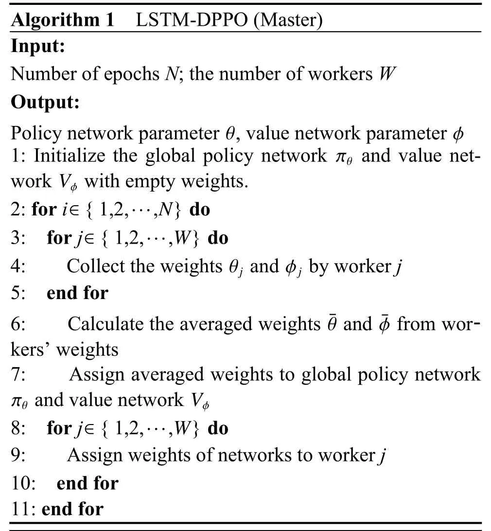
The proposed LSTM-DPPO algorithm consists of workers and a master.The workers have several instances,which run in separate processes.The workers are responsible for collecting data from experience,calculating the gradients of the policy and value networks,updating the network weights locally,transmitting local weights to the master,and receiving the network weights from the master to replace the old local weights.This process is repeated continuously until the end of the training.The master assumes the responsibility of scheduling and managing workers,summing up the weights transmitted from workers,calculating their average weights as the global weights,and sending the latest global weights to the workers.Algorithm 1 and Algorithm 2 describe the realization process of LSTM-DPPO.
5.Simulations
To verify the proposed USV path following algorithm,the random path dataset was employed to train the LSTMDPPO controller network.First,the LSTM-DPPO controller at different training stages is extracted to analyze the algorithm’s self-learning capability;then,the path following performance of the controller is tested in the standard path dataset.Subsequently,the angle and distance errors,as well as the average rewards,are calculated to compare the LSTM-DPPO algorithm with other control algorithms in terms of tracking performance.Ultimately,to verify the contribution of the path dataset to the control performance,the LSTM-DPPO algorithm is studied with different volumes of the dataset.Various scales of path samples are intercepted from the random path dataset to train the controller network from scratch,which is tested by the standard path dataset.
The USV controller is trained in a server with two E5-2 678 V3 CPUs and four RTX 2080Ti GPUs.The parameters for the LSTM-PPO algorithm are configured as follows.The number of workers is eight (two working processes for each graphic card).The number of training epochs was set to 1 000;the rollout size is selected as 8 192.The LSTM input time step rangeTis selected as 30.A discount factor was selected as 0.99.The number of subiterations with policy and value updates is set to the default value of ten.For the network training,an Adam optimizer is used to train both the policy and value networks.The learning rate is set to 10-4.The USV environment parameters are configured as follows: simulation timestep is defined as 0.1 s (10 Hz).The path lengthLis set to 2 km.The boundary length is selected as 400 m.The curved path ratiorcis selected as 0.4.The sample size of the random path dataset is set to 1000.The desired speed in each training epoch was generated randomly between 2-8 m/s.Reward adjustment coefficientskψ,ky,ku1,andku2are 0.1,0.1,0.2,and 0.2,respectively.Reward weightswψ,wy,wu,andpare 1/3,1/3,1/3,and 0.7,respectively.
Fig.13 presents the training curves of the LSTMDPPO controller with a random path dataset.The accumulated reward in the first 230 epochs increased monotonically in an S-shaped curve after smoothing,and soared from -1 420 to 810.Subsequently,it oscillated around 800.The accumulated reward does not become stable at the late stage of training,but constantly oscillates within a favorable interval.Through the USV visualized environment,it can be seen that the desired speed stochastically causes the oscillation of the accumulated reward.When the desired speed is lower,it is easier to control the USV,and the path following error is smaller.In contrast,if the desired speed is larger,the USV needs to frequently adjust the state for path following under the limited maneuverability,causing a more significant path following error,so that the accumulated reward is poorer.

Fig.13 Training curve of the LSTM-DPPO
To analyze the self-learning capability of the LSTMDPPO algorithm,the weights of the policy network at different stages of training are extracted to test for all the standard path dataset.Square and rounded rectangular paths are taken as the typical polygonal and curved paths for analysis and illustration.The test parameters are set as follows: USV initial position is (-30,-30);desired speed is 5 m/s;the initial heading angle is given randomly;the maximum operation epoch is 3 000 steps.
Fig.14 and Fig.15 present the path following trajectory of the LSTM-DPPO algorithm on typical polygonal and curved paths at different stages of training.Fig.14(a)and Fig.15(a) show the result at the beginning of training,that is,the USV turned in a circle at the origin.As the training epochs increases,the USV learns to follow the mission path stably,but can not control its speed accurately.The speed is so low that the USV can not reach the endpoint of the path within the specified time steps in the episode (see Fig.14(b) and Fig.15(b).After 200 training epochs (see Fig.14(c) and Fig.15(c)),the USV can travel to a farther position along the mission path,but large errors could be still observed at the turning position of the polygonal path (see Fig.14(c)).Compared with the polygonal path,the curved path has a much smaller following error (see Fig.15(c)).It can be explained that the curved path is smooth and continuous,causing the continuous variation of the USV heading error angle,but the discontinuity of the polygonal path caused an abrupt change of the USV heading error angle,resulting in a large tracking error for the USV at the turning positions of the polygonal path.After 1 000 training epochs,the USV can finish all the paths within the specified time steps,and the tracked trajectory reached the ideal state (see Fig.14(d) and Fig.15(d)).After observing Fig.14(d),it is found that the USV had a more continuous and accurate trajectory at the turning position.Fig.16 and Fig.17 present the heading angle error and cross-track error curves corresponding to the typical polygonal and curved paths,respectively.The convergence rates of both heading angle errors and cross-track errors have been significantly improved along with the increase of training epochs.

Fig.14 Trajectory of a typical polygonal path following with LSTM-DPPO
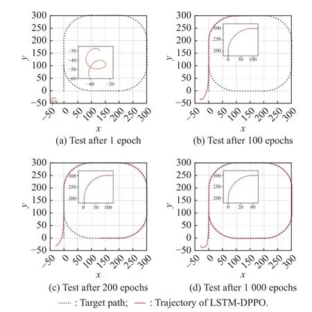
Fig.15 Trajectory of a typical curve path following with LSTMDPPO

Fig.16 History of the heading angle and cross-track errors during the typical polygonal path following experiments with various training epochs
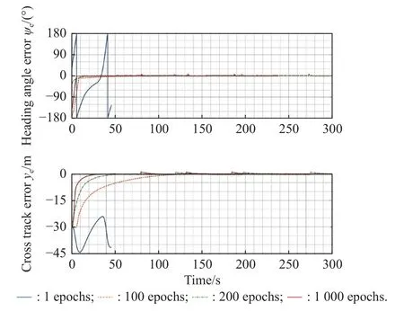
Fig.17 History of the heading angle and cross-track errors during the typical curved path following experiments with various training epochs
To further analyze the advantages and disadvantages of the LSTM-DPPO algorithm when compared with other algorithms,three control methods were selected for comparison,including an MLP-PPO algorithm (with LSTM layer deleted but other parameters unchanged compared with LSTM-DPPO algorithm),a classic PID control algorithm,and a human player using a joystick for USV control.Fig.18 and Fig.19 present four different trajectories of following the typical polygonal and curved paths.The trajectories of path following with four methods including LSTM-DPPO,MLP-PPO,PID and human player,are indicated in red,purple,yellow,and green,respectively.As revealed in Fig.18,these four control methods can ensure the stable following of a straight path,but their differences exist mainly in the control of turning performance.The enlarged detail in the upper right corner of Fig.18 clearly shows that a well-trained LSTM-DPPO controller has the best performance since it could achieve rapid convergence of trajectory error.The MLP-PPO controller had a slower response and larger trajectory error.The PID controller faces overshoot and oscillatory convergence in the trajectory.The joystick is used to manipulate the USV throttle and rudder angle for manual path following control along each path in the standard path dataset.As shown in the green trajectory in Fig.18,the human player can achieve a good effect by controlling the USV under the brain-image-joystick feedback mechanism.Fig.19 shows the effect of following various control methods on a curved path.After observing the trajectories of following a curved path,it is found that LSTM-DPPO and MLP-PPO could control the crosstrack error to a small range;the PID algorithm lag behind to some extent,and its trajectory is normally at the external edge of the turning position.Control of following the curved path was fairly challenging when using a joystick,which had the most significant path following error.

Fig.18 Trajectories of following the typical polygonal path with four control methods
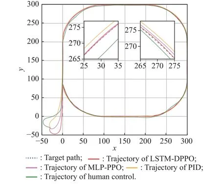
Fig.19 Trajectories of following the typical curved path with four control methods
Fig.20 and Fig.21 contain the heading angle and crosstrack error curves of the four control methods with regard to the two typical paths.The LSTM-DPPO algorithm could control the angle and distance errors faster than the other methods,and reach the ending point within the shortest period.
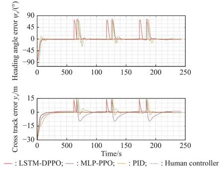
Fig.20 History of the heading angle and cross-track errors during the typical polygonal path following experiments with four control methods
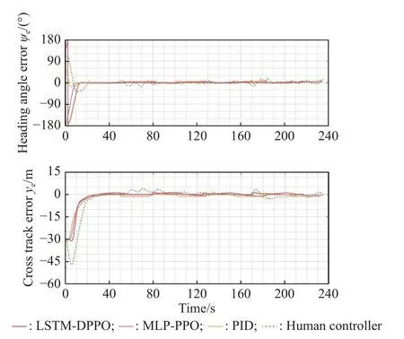
Fig.21 History of the heading angle and cross-track errors during the typical curved path following experiments with four control methods
Table 2 shows the performance indices of various control methods in the path following test with a standard path dataset.There are three test conditions: a polygonal path,a curved/mixed path,and a combination of all paths above.The test indices include the root mean square(RMS) of heading angle error (H.A.E.),cross-track error(C.T.E.),and corresponding average reward (accumulated reward/simulation step size).The bolded item in each row represents the optimal value which is the minimum error.As revealed in Table 2,the average reward of the LSTM-DPPO method goes up constantly with the increase in training step size.Compared with the three other control methods,LSTM-DPPO performed better in all the performance parameters under a polygonal path test condition.In the curved/mixed path,the average reward was basically consistent among the LSTM-DPPO,MLP-PPO and PID methods.It can be interpreted that the training dataset is a combination of curves and straight lines,including sudden turns and even reversals.These features are similar to the polygonal path in the test dataset,so a better simulation result can be obtained in the polygonal path.However,the curved/mixed path in the test dataset is dominated by smooth and continuous curves,which are different from the training dataset in terms of path features,but the DRL controller still performs at a good level even though its performance is slightly inferior to PID controller.From the perspective of all the standard path dataset,the proposed algorithm has the remarkable capability to adapt to different paths and achieve the superior control performance of path following.

Table 2 Comparison results of the RMS for H.A.E.and C.T.E.during the path following validation
To verify the path dataset’s contribution to control performance,1,10,100,and 1 000 random path samples are intercepted from a random path dataset to form a training set.With the other training parameters unchanged,the LSTM-DPPO controller network is trained from scratch and tested with the standard path dataset.The results are given in Table 3.It is found that an increase in path training sample size improves the error and average reward of the controller.Moreover,the table reveals that if the training sample size is 100,the controller has a better performance index on the curved/mixed path,but a poorer performance index on the polygonal path when compared with the size of 1 000.It is assumed to be that controller adjusts the learning policy in the process of selflearning to cope with various paths.When the control policy is completely fitted with the polygonal path,it will sacrifice a certain degree of fitting with the curved/mixed path.Hence,when the volume of learning samples increases,the controller could gradually learn how to balance the control policy through reinforcement learning while taking into account different paths to improve the comprehensive control performance constantly.
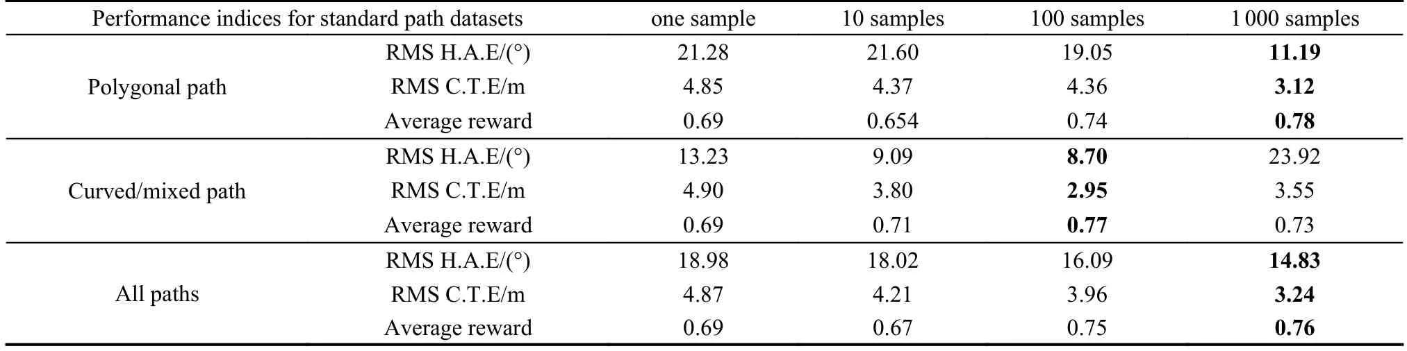
Table 3 Comparison results of the RMS for H.A.E.and C.T.E.in the varis scale of data set
6.Conclusions
This paper proposes a path following control method for USV with LSTM-DPPO based deep reinforcement learning.To enhance the controller’s generalization and practicality,a path dataset is constructed,and the corresponding LSTM-DPPO algorithm is developed to meet the requirements of model training.The simulation results show that the proposed LSTM-DPPO method could improve the performance of the path following,lower the heading angle and cross-track errors,and increase the average reward along with the increase of training epochs,which is superior in the most cases to other control methods including MLP-PPO and PID.Additionally,the contribution of the path dataset to control performance is also verified in the test.This reveals that having diversity in the training environment for reinforcement learning could be beneficial to the controller’s network generalization performance.Future work will focus on the application of the LSTM-DPPO method in the USV in real.
 Journal of Systems Engineering and Electronics2023年5期
- Journal of Systems Engineering and Electronics的其它文章
- Reliability analysis for wireless communication networks via dynamic Bayesian network
- Attention mechanism based multi-scale feature extraction of bearing fault diagnosis
- Anti-interference self-alignment algorithm by attitude optimization estimation for SINS on a rocking base
- TOA positioning algorithm of LBL system for underwater target based on PSO
- Scene image recognition with knowledge transfer for drone navigation
- Leader trajectory planning method considering constraints of formation controller