
Leader trajectory planning method considering constraints of formation controller
2023-11-06 14:19:44YAODongdongWANGXiaofangLINHaiandWANGZhuping
YAO Dongdong ,WANG Xiaofang,* ,LIN Hai ,and WANG Zhuping
1.School of Aerospace Engineering,Beijing Institute of Technology,Beijing,100081,China;2.Xi’an Institute of Electromechanical Information Technology,Xi’an,710065,China
Abstract: To ensure safe flight of multiple fixed-wing unmanned aerial vehicles (UAVs) formation,considering trajectory planning and formation control together,a leader trajectory planning method based on the sparse A* algorithm is introduced.Firstly,a formation controller based on prescribed performance theory is designed to control the transient and steady formation configuration,as well as the formation forming time,which not only can form the designated formation configuration but also can guarantee collision avoidance and terrain avoidance theoretically.Next,considering the constraints caused by formation controller on trajectory planning such as the safe distance,turn angle and step length,as well as the constraint of formation shape,a leader trajectory planning method based on sparse A* algorithm is proposed.Simulation results show that the UAV formation can arrive at the destination safely with a short trajectory no matter keeping the formation or encountering formation transformation.
Keywords: trajectory planning,formation control,prescribed performance controller,multiple constraints,formation shape,formation transformation.
1.Introduction
Multi-unmanned aerial vehicle (UAV) formation has more and more applications.The formation of multiple UAVs can improve the efficiency of taking tasks.When multiple UAVs fly in a formation,it is vital to consider obstacle avoidance and collision prevention.Thus,trajectory planning for UAV formations is of great significance [1,2].There are many researches on single aircraft path planning [3,4].
Research on the trajectory planning of multiple aircraft is relatively sparse compared with that of single aircraft.Using the Dubins curve,it is possible to obtain a multi-missile trajectory satisfying the impact time constraint [5].Aiming at the problem of multiple aircraft reaching the target from different directions at the same time,the relationships between the control points of a Pythagorean hodograph (PH) curve and the impact angle,trajectory length,and tangential acceleration have been analyzed [6],allowing a cooperative path planning method based on the PH curve to be developed.Considering the impact angle and impact time constraints,a cooperative trajectory planning algorithm based on three circular arcs was reported [7],and the total cost across multiple aircraft has been used for cooperative trajectory planning with the minimum total threat under a bi-level programming framework [8].The core of the abovementioned trajectory planning methods for multiple aircraft is to add an impact time constraint on the basis of the trajectory planning method for single aircraft,and realize simultaneous attack by designating the same impact time.Under the action of a formation controller,each member’s motion state is consistent and the relative distance is stable,and so the trajectory planning problem for multiple aircraft can be regarded as that of a single aircraft,namely the leader [9].According to the conclusions reported in [9],the constraints associated with the minimum turning radius,maximum curvature,and maximum torsion were considered in terms of the PH curve to realize the trajectory planning of multiple aircraft [10].A new formation control scheme is developed by integrating smooth distributed consensus control protocols into the geometric pattern model to achieve cooperative control of three-dimensional multi-UAV formation [11].However,while considering the trajectory planning for a UAV formation,since it is different from the cooperative trajectory planning of above [5-8],the algorithm in [5-8]cannot be used here.In addition,in [9-11] on the premise that the formation has been formed,considering multiple constraints such as maximum turning angle and terrain avoidance,the leader’s trajectory was planned.However,when consider the trajectory planning of whole UAV formation,the space occupation of formation shape should be taken into account.Moreover,when the formation shape changes,the transient formation transformation also should be considered.Otherwise,one UAV may collide with another or with some other obstacles.However,the transient response of formation transformation is decided by formation controller.So,when discussing the trajectory planning for the UAV formation,the trajectory planning and formation control should be considered together.However,to the authors’ knowledge,there is rare research on this area.In most of research,the problem of trajectory planning and that of formation control are studied separately.
In the research field of aircraft formation,traditional formation modes include leader-follower mode [12,13],distributed mode [14],virtual structure mode,and behavior control mode.The leader-follower mode is widely used because of its simple operation.In the leader-follower mode,the transient UAV formation is highly dependent on the followers ’ formation controller.The different characteristics of specific formation controllers will lead to different transient formations.There has been a great deal of research on the design of a formation controller [15].For instance,a formation algorithm based on consistency theory was designed to realize the creation and maintenance of the formation [16].A formation controller for multiple aircraft based on relative state feedback was designed under local communication conditions [17],and a formation controller based on sliding mode control theory was developed [18],with the feasibility conditions of the formation under observation constraints analyzed in detail.Under communication faults,an event-triggered formation controller was designed by consensus theory,realized the stability control of multi-UAV formation [19].The dynamic feedback adaptive formation keeping control is designed to realize the effectiveness and stability of UAV formation keeping [20].A formation controller based on deep reinforcement learning dueling double deep Q-network (D3QN) algorithm was designed,and the intelligent method was applied to formation control [21].In the above references,the researches on formation control mainly focus on how to form and maintain the designated formation configuration with good accuracy,while do not care about the transient formation,i.e.,they cannot control the process of formation forming and changing,which may cause collision between aircrafts or collision with surrounding terrain.
Prescribed performance control is a new control method that has been developed in recent years.By designing an error transformation function,the system error converges to a preset region,thus ensuring that the transient response and steady-state response of the system meet the preset boundary conditions [22].The method actively controled the transient and steady-state response of the system,and was applied to the trajectory tracking control of hypersonic vehicles,robots,and ships[23-26].Combining the prescribed performance theory and adaptive control theory,a back-stepping controller for carrier-based UAV was designed in reference [27],which realized the attitude control of the UAV.Combining the prescribed performance theory and state observation method,an attitude controller for fixed trim reentry vehicle considering the actuator input and power constraints was designed in [28],which realized the attitude control of the fixed-trim reentry vehicle.
In this paper,aiming at the problem of trajectory planning for UAV formation,a formation controller is designed based on prescribed performance theory,which not only can make UAVs to form the designated formation configuration but also can guarantee collision avoidance and terrain avoidance during formation transformation and control the formation forming time theoretically.Then considering the coupling of trajectory planning and formation control,the steady-state formation shape,the formation forming time,the overshoot of the formation controller are mapped as the constraints of the trajectory planning of the leader.By considering the constraints imposed by the terrain,mapped from the formation controller and the UAVs’ maneuverability,a trajectory planning algorithm for the leader based on the sparse A*algorithm is proposed,which get a short and safe trajectory not only for the leader but also for the whole UAV formation.The effectiveness of the proposed algorithm is verified through the simulation.
The remainder of this paper is organized as follows.Section 2 presents the background to the problem considered herein.Section 3 introduces the relative motion model and the design of the prescribed performance formation controller,and describes the trajectory planning algorithm under multiple constraints.Section 4 presents simulation results.Finally,conclusions are given in Section 5.
2.Multi-UAV formation control
Assuming that multiple UAVs adopt the leader-follower formation mode,an initial formation is set up according to the combat task,the map,and the functions of detection and communication.In this initial formation,the UAVs may not pass safely through a narrow area due to particular obstacles.If the UAV formation makes a detour to avoid the terrain,the flight time will increase and the combat efficiency will be reduced.If multiple UAVs have the ability to change the shape into a smaller one,they can pass through the narrow area safely.The above process is illustrated in Fig.1.
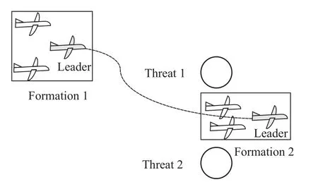
Fig.1 Changing UAV formation for passing through a narrow area
In the process of transforming between different formations,the relative position of the leader and the followers changes.If the instantaneous formation is not considered,the UAV formation may not be able to pass safely through the local obstacles.To control the instantaneous formation in the process of transforming between different set formations,as well as to collision avoidance,a formation controller based on prescribed performance control theory is designed.This scenario also provides some constraints for the leader’s trajectory planning.
2.1 Formation model
Consider a leader and a single follower as an example.The inertial coordinate system,leader trajectory coordinate system,and follower trajectory coordinate system are denoted byAxyz,olxlylzl,andof xfyfzf,respectively,and the absolute position vector of the leader,absolute position vector of the follower,and position vector of the follower relative to the leader are denoted byrl,rf,andrrespectively.The relative motion relationship is illustrated in Fig.2.
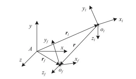
Fig.2 Relative motion relationship between leader and follower
Definer=[x,y,z]T,wherex,y,andzare the projections of the follower in the coordinate system of the leader’s trajectory.Taking the leader trajectory coordinate system as the reference system,the relative motion equations for the l eader and follower are given [29] as follows:
whereVlandVfare the speed of the leader and the follower,θland θfare the path angle of the leader and the follower,ψvland ψvfare the deflection angle of the leader and the follower,andax,ay,azare the tangential and normal accelerations.
Define the variables
The formation model given by (4) has a strict cascade form.The purpose of the formation controller is to design the normal acceleration of the follower so that the distanceRbetween the follower and the leader tends toR∗,which defines the designated formation.Finally,the new formation is created.
2.2 Design of prescribed performance formation controller
For the cascaded strict feedback nonlinear system given by (4),prescribed performance control (PPFC) theory is used to design the formation controller.The controller has the following objectives:
(i) To achieve the designated formation.
(ii) To control the transient formation so as to avoid collisions between UAVs.
(iii) To satisfy the constraint regarding the time required to create the desired formation.
First,the prescribed performance function is designed as
where ϖ0,ϖ∞,andpare constants.ϖ0is the initial error boundary,ϖ∞is the upper limit of the steady-state error,andpcontrols the convergence rate of the error.A larger value ofpgives a faster response time.
The constantsldown>0 andlup>0 satisfy
wheree(t) is state error of the system;-ldown(t)ϖ(t) andlup(t)ϖ(t)denote the lower and upper boundaries of the error,respectively.
The error transform function is denoted by
where ε is a conversion function defined by
Based on the first part of (4),the state errore1of the UAV formation system is defined as
whereX1c=[x∗,y∗,z∗] expresses the relative position between the follower and the leader under the designated formation.Substituting the errore1into (8) and differentiating with respect to time,and considering the first part of (4),the derivative of ε is get
where
wherek1>0 andk2>0 are design parameters.
To avoid the need to differentiate this variable,X2cis passed through the f ollowing first-order low-pass filter
where τ2is the time constant andX2dis the output of the filter.
Based on the second part of (4),the errore2is defined as
Differentiating this expression with respect to time and considering the second part of (4),the control variable is designed
According to PPFC theory,if the followers adopt the control variables in (14),the relative position error of the formation will tend to zero in the adjustment process,and the response curve of the error will not exceed the upper and lower boundaries defined in (6),as shown in Fig.3.

Fig.3 Relationship between formation error and performance function
Under the leader trajectory coordinate system,coordinates of the follower in Formation 1 and Formation 2 (see Fig.1) are (x1i,y1i,z1i) and (x2i,y2i,z2i).The two formations satisfy
wherenis the number of followers.
When the formation changes from Formation 2 to Formation 1 (formation expansion),there is some position state overshoot during the response process.This is illustrated by Response 1 in Fig.4.At this time,taking Formation 2 as the basis to judge whether there is a collision between terrain and UAVs,collision may occur when UAVs are in the transient formation,which does not necessarily satisfy the security requirements.The parameters of the prescribed performance formation controller can be set so that the system response does not have this overshoot shown,as illustrated by Response 2 in Fig.4.In this way,during the transformation process,the UAV is always in the range of Formation 1,i.e.,|e(t)|≤|e(0)|,thus avoiding any collision with the terrain.
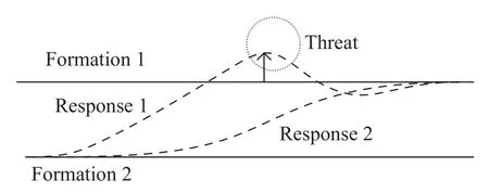
Fig.4 Safety judgment of formation change process
When Formation 1 changes to Formation 2 (formation shape shrink),if there is any overshoot in the relative position,the UAVs may collide with one another in the process of formation change.Therefore,some parameters of the prescribed performance formation controller are set to ensure that there is no overshoot of the system state,thus preventing collisions with the terrain or between the UAVs.
The error attenuation index is denoted by δ.The error satisfies |e(t)|≤δ|e(0)|(0<δ),and the response is considered to be in the steady state in this paper.If the initial error is greater than zero,lupis usually set to 1.Setting the lower boundary close to zero,i.e.,ldown≤δ,ensures that the overshoot is very small or zero during the whole process (i.e.,within some allowable range of the steady state).If the initial error is less than zero,thenldownis set to 1 andlup≤δ.
The step length of trajectory planning is affected by the response time of the formation.In trajectory planning,each search step starts after the formation enters the steady state.Otherwise,the determination of terrain avoidance will no be accurate,which may result in collisions.Thus,the longest timeTsrequired for creating the formation is set,as the time of one step for trajectory planning.
According to the relationship between the performance function and the system error shown in (5),constantpshould satisfy
After transformation,the constraint forpso as to adjust the response time is as follows:
3.Trajectory planning algorithm under multiple constraints
3.1 Constraints analysis of trajectory planning
3.1.1 Constraints of step length and turning angle
In this study,the sparse A∗algorithm [30] is used to realize the trajectory planning for the leader.The minimum trajectory segment is defined as the shortest direct flight distance before the formation changes.For a UAV formation,changes in the flight status can only be performed when the formation is stable.Therefore,the trajectory planning step lengthlis set according to the longest time required to create the formation:l=vl·Ts.
The geometric relationships when a UAV makes a turning maneuver are shown in Fig.5.
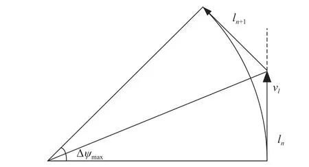
Fig.5 Turning angle constraint
In Fig.5,lnandln+1are two consecutive segments,and Δψmaxis the maximum turning angle.The longitudinal and lateral available overloads are denoted bynymaxandnzmax,respectively.When the UAV is flying with the available overload in the horizontal plane,the following relationship holds:
wheregis gravitational acceleration.Thus,considering the available overload constraint,there is a inequality relation
Similarly,in the vertical plane,the inequality relation is
To ensure the safety of climbing (diving),the amplitude of θ should be limited as follows:
where θmaxis the maximum climb (dive) angle.
3.1.2 Formation security constraints
When the UAV formation is in the steady state,the ballistic inclination and deflection angles of all UAVs are the same,which means θf=θl=θ,ψf=ψl=ψ.The resulting of UAV formation is shown in Fig.6.
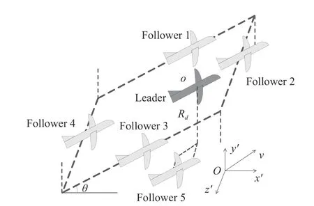
Fig.6 Diagram of formation boundary
In Fig.6,the coordinate systemOx′y′z′is obtained by rotating the trajectory coordinate system of the leader by-θ about theZaxis.At present,the coordinates of the leader areand those of the follower
The front,back,left,and right boundary interfaces are defined as
To avoid any collision with the terrain,when planning the leader’s trajectory,it is necessary to consider the space occupied by the steady formation configuration of UAVs and the relative position between the formation and the terrain.Fig.7 shows a trajectory segment of the UAV formation.

Fig.7 Formation configuration space position
In Fig.7,the leader is colored dark gray and the followers are colored light gray.The safe distance (light blue solid lines) is denoted byRsafe,indicating the shortest distance from the formation boundary to the terrain edge.At the beginning of the trajectory,the intersection of the front,back,left,and right boundaries and the lower boundary forms a rectangle S1 (green part).In the coordinate systemOlx′y′z′,the coordinates of the verticesA,B,C,andDare
Rectangle S2 can be obtained by translating S1 vertically downward byRsafe.Rectangle S3 can be obtained by extending S2 along the trajectory segment direction by a distance ofl.Rectangle S4 can be obtained by extending S3 outward.The vertex coordinates of S4 are
The relationship between the coordinate systemOlx′y′z′and the inertial coordinate system is
The coordinates of pointA4(x,y,z) in the ground coordinate system are
The coordinates ofB4(x,y,z),C4(x,y,z),D4(x,y,z) can be obtained similarly.
Compare S4 with the terrain map projected vertically.If S4 does not cross the map,then that part of the trajectory is safe;otherwise,that section is dangerous.In the ground coordinate system,if the elevation of rectangle S4 isys4(x,z) and the elevation of the terrain ish(x,z),the following security constraint prevents the whole formation from colliding with the terrain
3.2 Trajectory planning algorithm based on sparse A∗ algorithm under multiple constraints
In the A∗algorithm,the cost of all the current expanded child nodes is calculated,and that with the minimum cost is selected to join the search space for further expansion.When the formation can reach the target safely from the current node,the trajectory planning is complete.
The basic search direction is classified into forward,up,down,left,and right.Considering the maximum turning angle constraint expressed in (18)-(20),the search considers the remaining area with the specified step length.A diagrammatic sketch of the two-step A∗search process is shown in Fig.8.
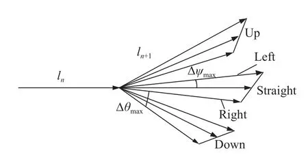
Fig.8 Schematic diagram of algorithm space search
In Fig.8,nandn+1 denote consecutive steps.The turning angle of the up and down directions is not more than Δθmax,and that of the left and right directions is not more than Δψmax.
Considering the space constraint of the formation,security detection should be performed in each extended trajectory segment.If the UAVs can pass through the terrain safely with Formation 1,they will do so.If not,there are two alternative schemes:
(i) Choose a detour.
(ii) Change to Formation 2.
The cost function can be set as
wherenis the current node,g(n) expresses the real generation value from the start node to the current node,andh(n)is an heuristic function representing the estimated cost from the current node to the target point.This heuristic function consists of two components,the linear distance from the current node to the target point (denoted byl) and the cost of formation transformation (denoted byc).Whencis small,the strategy of changing formation is preferred.Whencis large,however,the detour strategy is preferred.The algorithm flow is as follows.
(i) The shapes of Formation 1 and Formation 2 are designed according to the battleground terrain and the UAVs’ mission.
(ii) The prescribed performance controller is designed according to the minimum track length and safety requirements,so that the relative position error between the follower and the leader can converge to zero and there is no overshoot during the formation transformation process.The response time constraint given by (17) must also be satisfied.
(iii) According to the available overload of the UAVs and the minimum track length,the turning angle constraint in (19)-(21) is established.According to the spatial position of the formation,the collision avoidance constraint in (27) is derived.
(iv) The sparse A∗algorithm with formation judgment is used to plan the leader’s trajectory,and the initial trajectory satisfying various constraints is obtained.
Finally,the rule used to transform between formations is derived.Fig.9 shows three trajectory segments of this process.SegmentsABandCDare Formation 1 flight segments,and segmentBCis a Formation 2 flight segment.To ensure safety,the UAV formation must enter segmentBCin Formation 2 and maintain this formation until the end of the segment.Therefore,the formation changes from Formation 1 to Formation 2 at pointA,and back to Formation 1 at pointC.In addition,if there is only one track of Formation 1 between two tracks of Formation 2,then Formation 2 can be maintained over that track.
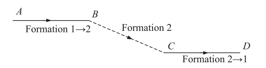
Fig.9 Schematic diagram of trajectory segment for formation transformation
Based on several points along the leader’s trajectory,a B-spline function is used to determine the continuous trajectory.On the premise of the leader flying with the planned trajectory,the followers then form,maintain,and change formation according to the prescribed performance formation controllers.
4.Simulations and analysis
This section is devoted to demonstrating simulation results.The simulation is completed by Matlab 2016a.
4.1 Map generation
The map can be obtained using the following equations:
where (xm,zm) is the sea level,ym1is the peak height of the terrain,andym2is the height of some cylindrical terrain;a,b,c,d,e,andfare random numbers.Around the peak-height terrain,(xi1,zi1) are the center coordinates at sea level andhi1is the central height.For the cylindrical obstacle,(xi2,zi2) are the center coordinates,hi2is the height,andRis the radius.
The map parameters are presented in Table 1.

Table 1 Map parameters m
Assuming that bothxandzrange from 0-2 000 m,the resulting map is shown in Fig.10.
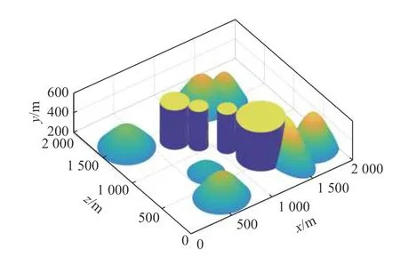
Fig.10 Schematic diagram of map
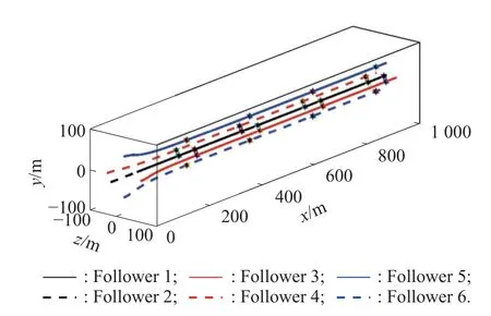
Fig.11 Trajectory of formation
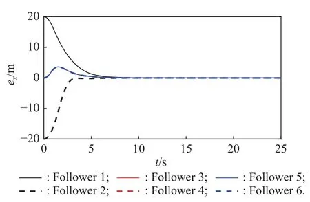
Fig.12 Simulation result of ex
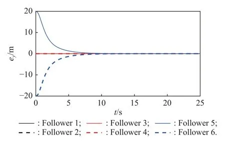
Fig.13 Simulation result of ey
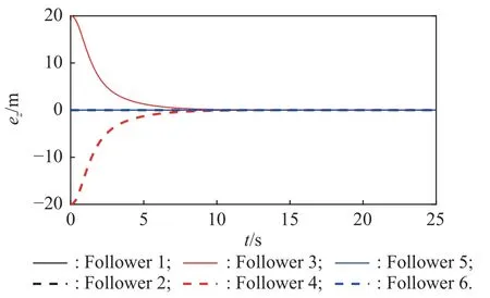
Fig.14 Simulation result of ez
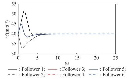
Fig.15 Simulation result of v
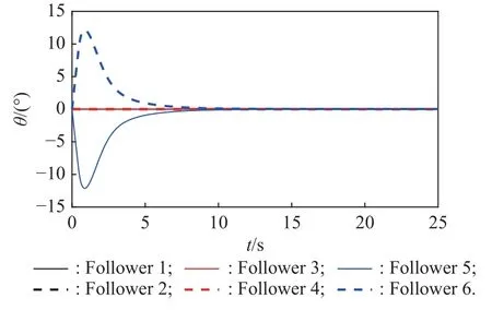
Fig.16 Simulation result of θ

Fig.17 Simulation result of ψv
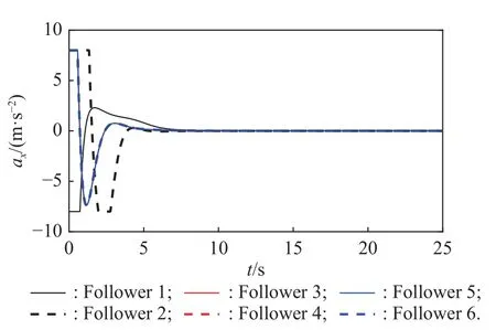
Fig.18 Simulation result of ax

Fig.19 Simulation result of ay
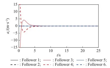
Fig.20 Simulation result of az
4.2 Performance analysis of prescribed performance formation controller
Assuming that a formation has one leader and six followers.The parameters of formation 1 are presented in Table 2.According to the formation shape and terrain parameters,it can be seen that when the UAVs fly in Formation 1,they cannot pass between the two cylinders.Thus,Formation 2 is designed to pass through the two cylinders.The parameters of Formation 2 are also given in Table 2.
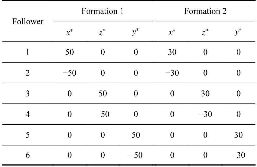
Table 2 Relative position of followers in two formations m
The initial position and speed of the leader are(0,0,0)andV1=40 m/s.The initial flight path and trajectory deflection angles of all UAVs are 0°.Given that,ϖ(0)=1.5×e(0),ϖ (∞)=0.1,ldown=0.01,lup=1(e0>0),k1=0.1,k2=5×10⁻⁵,k3=3,andg=9.8 m/s2,the available overload of the UAVs in thex,y,andzdirections arenxmax=0.8,nymax=1.5,andnzmax=1.5.The allowable maximum formation time isTs=10 s.The parameterp≥0.57 is obtained from (15).Takingp=0.6,δ=0.02.Thus,when the error in each direction is less than 0.4 m,the formation is considered to have formed.The simulation results are shown in Figs.11-14.
From Figs.11-14,it is clear that the formation can transform into Formation 2 within 10 s,and there is no collision between UAVs during this process.
The velocity,flight path angle,trajectory deflection angle,and control variable of the followers are shown in Figs.15-20.
It can be seen that the velocities of the six followers become consistent with that of the leader within 10 s.The control variable of each UAV is within the available overload range.
Taking Follower 3 and Follower 6 as examples,the variation in relative position error,upper boundary,lower boundary,and the steady state value are shown in Fig.21 and Fig.22.
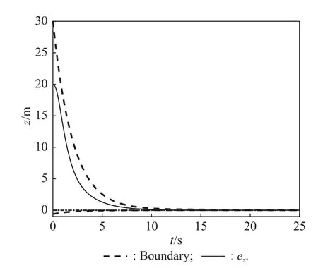
Fig.21 Simulation result of ez for Follower 3

Fig.22 Simulation result of ey for Follower 6
Fig.21 and Fig.22 illustrate that the corresponding relative position errors of the two followers are always within the upper and lower boundaries,which demonstrates the validity of the prescribed performance controller.The initialezof Follower 3 is 20 m,the initial value of the upper boundary is 30 m,and the initial value of the lower boundary is -0.4 m.Fig.21 shows thatezis greater than 0 during the whole process,decreasing to 0.4 m after 6.65 s,at which point the formation configuration is formed.Thus,the formation forming time is less than 10 s.The initialeyof follower 6 is -20 m,the initial value of the upper boundary is -30 m,and the initial value of the lower boundary is 0.4 m.Fig.22 shows thateyis greater than 0 throughout the process,decreasing to -0.4 m after 6.65 s.Again,the formation forming time is less than 10 s.As seen from Fig.21 and Fig.22,the prescribed performance formation controller can control the steady-state and transient processes as well as the convergence time.The errors of the other followers are the same.
To demonstrate the advantages of the prescribed performance formation controller,a comparation between the results given by the dynamic surface formation controller (DSFC) [19] and PPFC are given.For DSFC,the control command given by (14) does not change,but (11)becomes
Fig.23 shows the formation trajectory with DSFC,and compareseyfor Follower 6 under the two controllers as an example of the followers’ error.
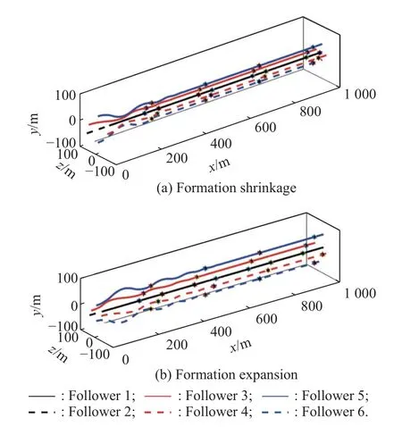
Fig.23 Formation trajectory with DSFC
As can be seen from Fig.24,eytends to zero under the action of both controllers,which means that the designated formation is eventually reached.However,during the process,the variation ineyis different under the two controllers.Under the proposed PPFC,eyalways remains within the set error boundary,and decreases close to 0 within the specified time.In contrast,under DSFC,eyoscillates continuously and exhibits a degree of overshoot.In Fig.24,the maximum overshoot of Follower 6 is 14 m,theeyof Follower 4 also overshoots by 14 m.The distance between the two UAVs is 8.4 m in Fig.23(a).and there is a risk of collision.In Fig.23(b),the maximum width of the formation reaches 64 m,which is 14 m wider than that of Formation 2 (50 m).While using 50 m as a constraint of trajectory planning,there would be risks shown in Fig.24.However,while using 64 m,the consequence will lose accuracy.In addition,the response time is 14 s,which is longer than the maximum allowable time.To reduce this time,the parameter controlling the error in DSFC must be increased,but this will increase the overshoot and enhance the risk of collision.Therefore,DSFC cannot theoretically guarantee the error convergence time and the instantaneous changes in the control error.Fig.23 also shows that the formation trajectory under DSFC is relatively curved,meaning that there is a risk of UAVs collision in the process of transforming to a different formation.

Fig.24 Comparison of ey for follower 6 using DSFC and the proposed PPFC
4.3 Simulation of trajectory planning
Assume that the UAVs are initially flying in Formation 1 with a safety distanceR2=10 m and a minimum track segment of 400 m.According to (18) and (19),the maximum turning angle is 150°.Let the maximum allowable climbing (diving) angle be θmax=15°.Considering the calculation efficiency,set |Δθmax|=|Δψmax|=15°and θmax=15°in this example.The start and end points of the leader are listed in Table 3.
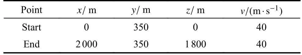
Table 3 Start point and end point of leader
Considering scenarios in which the cost of transforming the formation is significant,i.e.,c=400,and in which this cost can be ignored,i.e.,c=0.The results of route planning in each case are shown in Fig.25 and Fig.26,where the black and red lines denote the leader’s track in Formation 1 and Formation 2,respectively.
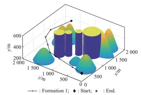
Fig.25 Leader’s trajectory with c=400
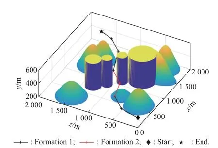
Fig.26 Leader’s trajectory with c=0
There is a narrow area between the two cylindrical obstacles in the center of the map.The width of the passage between the two is less than the width of Formation 1,but greater than that of Formation 2 (including the safety distance in each case).Whenc=400,the multiple UAVs will prefer to fly in Formation 1,and so the leader will make a detour to avoid the terrain,as shown in Fig.25.Whenc=0,the UAVs pass through the narrow area by changing to Formation 2,as shown by the red line in Fig.26.After passing through the narrow area,Formation 1 is restored.The length of the leader track in Fig.26 is 2 873 m (473 m less than the 3 346 m of the track in Fig.25),and the flight time is shortened by 11.8 s,effectively improving the viability and efficiency of the formation.
Here,the trajectory shown in Fig.26 is chosen and smoothed by a B-spline function to obtain the consecutive trajectory of the leader.The followers’ initial states are listed in Table 2.The followers adopt the prescribed performance formation controller to form,maintain,and change the formation while following the leader.The results are shown in Fig.27-Fig.30.
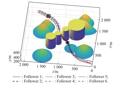
Fig.27 Trajectory of formation
As can be seen from Fig.27,the formation safely arrives at the destination from the starting point,and there are no collisions between the UAVs.First,with the prescribed performance controller,the followers’ relative position errors in thex,y,andzdirections are less than 0.4 m after 8.58 s,which is the point at which Formation 1 has formed.Before the UAVs enter the narrow area,the formation begins to transform into Formation 2 within 10 s.Formation 2 is maintained through the narrow area,before the UAVs transform back to Formation 1 after 40 s and keep flying to the terminal point,as shown in Fig.28-Fig.30.

Fig.28 Relative distance of X -axis
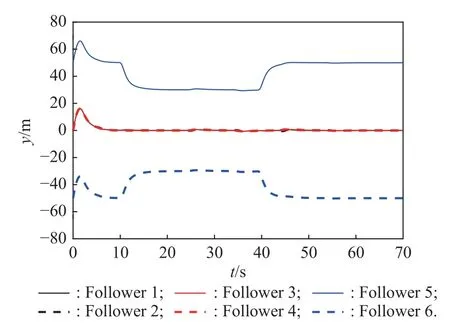
Fig.29 Relative distance of Y-axis

Fig.30 Relative distance of Z-axis
The comparisons between PPFC and DSFC are shown as follows.When the DSFC is used,the formation trajectory is got and shown in Fig.31.

Fig.31 Formation trajectory with DSFC
The relative position of each follower are shown in Fig.32-Fig.34,which show that the response time is longer than 10 s,and the formation cannot form the configuration quickly.And because of the overshoot,the relative position oscillates in the process of change.The oscillation is not conducive to the stable transition between different configurations,and may cause the risk of collision.
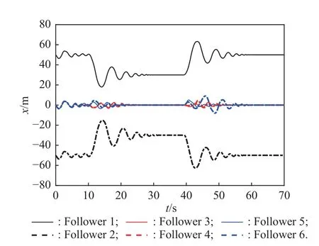
Fig.32 Relative distance of X-axis

Fig.33 Relative distance of Y-axis

Fig.34 Relative distance of Z-axis
If the relationship between the response time and the step length is not considered,and the results with the step length of 200 m are got as shown in Fig.35-Fig.38.When the formation follows the leader trajectory,the expected configuration cannot be formed in current trajectory segment.This is because the step length is 200 m,which means the response time is about 5 s.However,according to Fig.15,it takes at least 6.65 s to form a new configuration.Therefore,when the current steady-state formation is not formed,the desired configuration needs to be changed again.As shown in Fig.36-Fig.38 at 20-30 s and 40-50 s,the formation will also be in the process of adjustment rather than steady-state for a long time.If the formation cannot maintain a stable configuration,then the tasks like detection would be effectively completed.
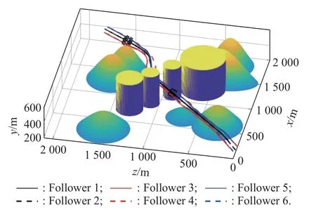
Fig.35 Formation trajectory with l=200 m
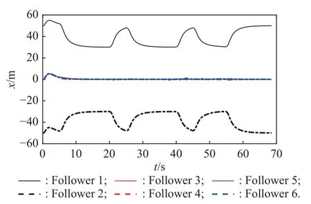
Fig.36 Relative distance of X
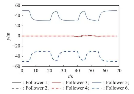
Fig.37 Relative distance of Y
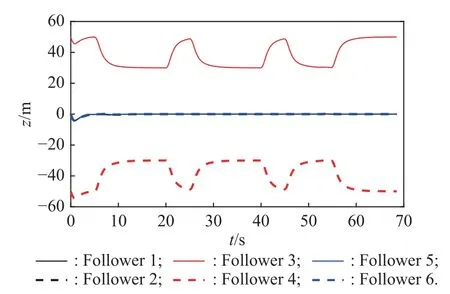
Fig.38 Relative distance of Z
In summary,before flying into the narrow area,the UAV formation changes from Formation 1 to Formation 2 safely and quickly,and there are no collisions between UAVs in the process.In the flight process of Formation 2,the formation does not collide with the terrain and passes through the area safely.After the trajectory segment of Formation 2 ends,the formation changes back to Formation 1 without colliding with the terrain during the transformation process.
5.Conclusions
Taking the leader in a fixed-wing UAV formation as the research object,and considering the constraints associated with the battleground terrain,UAVs’ maneuverability,formation shape,and response characteristics of the formation controller,a trajectory planning algorithm for the leader has been proposed based on the sparseA∗algorithm.The main research contributions of this paper are as follows.
(i) A prescribed performance formation controller is designed,which can not only control multiple UAVs to form a specified formation configuration,but also avoid collisions between UAVs during formation transformation and control the formation forming time theoretically.
(ii) Solve the problem of trajectory planning of UAV formation considering the coupling between trajectory planning and formation control.The steady-state formation shape,the transient formation and the adjustment time during formation transformation are all mapped to the constraints of the trajectory planning algorithm.Finally,a trajectory planning algorithm that could ensure the safe flight of UAV formation was obtained.
Future work will focus on cooperative path planning for multiple formations guided by multiple leaders in three-dimensional space.
 Journal of Systems Engineering and Electronics2023年5期
- Journal of Systems Engineering and Electronics的其它文章
- Reliability analysis for wireless communication networks via dynamic Bayesian network
- Attention mechanism based multi-scale feature extraction of bearing fault diagnosis
- LSTM-DPPO based deep reinforcement learning controller for path following optimization of unmanned surface vehicle
- Anti-interference self-alignment algorithm by attitude optimization estimation for SINS on a rocking base
- TOA positioning algorithm of LBL system for underwater target based on PSO
- Scene image recognition with knowledge transfer for drone navigation