Dynamic Visible Light Positioning Based on Enhanced Visual Target Tracking
Xiangyu Liu ,Jingyu Hao ,Lei Guo ,Song Song
1 School of Information Science and Engineering,Shenyang Ligong University,Shenyang 110158,China
2 Department of Computer Science and Engineering,Southern University of Science and Technology,Shenzhen 518055,China
3 School of Computer Science and Engineering,Northeastern University,Shenyang 110819,China
4 School of Communication and Information Engineering,Chongqing University of Posts and Telecommunications,Chongqing 400065,China
5 Hangzhou Institute of Advanced Technology,Hangzhou 310056,China
6 Institute of Intelligent Communications and Network Security,Chongqing University of Posts and Telecommunications,Chongqing 400065,China
*The corresponding author,email: songsong_eric@163.com
Abstract: In visible light positioning systems,some scholars have proposed target tracking algorithms to balance the relationship among positioning accuracy,real-time performance,and robustness.However,there are still two problems: (1) When the captured LED disappears and the uncertain LED reappears,existing tracking algorithms may recognize the landmark in error;(2)The receiver is not always able to achieve positioning under various moving statuses.In this paper,we propose an enhanced visual target tracking algorithm to solve the above problems.First,we design the lightweight recognition/demodulation mechanism,which combines Kalman filtering with simple image preprocessing to quickly track and accurately demodulate the landmark.Then,we use the Gaussian mixture model and the LED color feature to enable the system to achieve positioning,when the receiver is under various moving statuses.Experimental results show that our system can achieve high-precision dynamic positioning and improve the system’s comprehensive performance.
Keywords: visible light positioning;visual target tracking;gaussian mixture model;kalman filtering;system performance
I.INTRODUCTION
Nowadays,people spend more and more time in indoor activities,and the demand for indoor positioning technology is increasing significantly [1,2].Wi-Fi [3],Bluetooth [4],Infrared [5],Ultra-wideband(UWB)[6],Radio frequency identification(RFID)[7],ZigBee[8],and ultrasound[9]are common indoor positioning technologies.However,these technologies are difficult to find a balance between positioning accuracy and system deployment costs.
The light-emitting diode (LED) has brought a new revolution in the field of lighting and communication [10,11].It is an infrastructure widely used for indoor lighting,and its cost is low.The reasonable driving circuits can realize the rapid switching between “on” and “off” states for the LED,which is used for high-speed data communication and highprecision positioning [12,13].The LED-based visible light positioning technology can satisfy the system’s balance problem between positioning accuracy and deployment cost,its application scenarios are as shown in Figure 1.
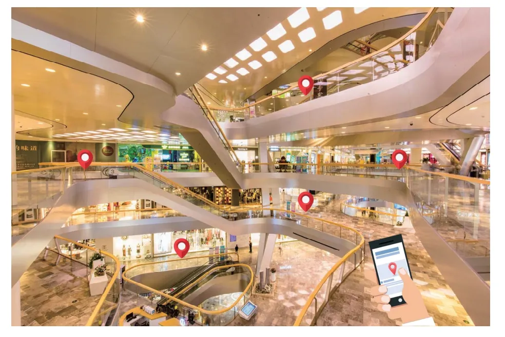
Figure 1.The visible light positioning is used in shopping malls.
There are three indicators for evaluating the performance of the visible light positioning system: positioning accuracy,real-time performance,and robustness[14,15].However,most scholars pay more attention to positioning accuracy,while ignoring real-time performance and robustness.Existing researches have used methods such as the continuously adaptive meanshift(Camshift),Kalman filtering,optical flow detection,and Bayesian forecast to increase the system’s real-time performance and robustness[16–18].
However,there are still two problems:(1)When the captured LED in the image disappears and the uncertain LED reappears,existing tracking algorithms may recognize the landmark in error;(2) The receiver is not always able to achieve positioning under various moving statuses.For example,in Ref.[17],the offset distance of the tracked LED between two frames cannot exceed two times the size of the LED,otherwise the positioning algorithm fails.
Therefore,in this paper,we propose the enhanced visual target tracking algorithm to achieve the visible light positioning system with high comprehensive performance.First,we design the lightweight recognition/demodulation mechanism,which is used to eliminate the possibility of the LED being wrongly judged.Our recognition/demodulation mechanism has four steps: including preprocessing,extracting the LED‘s region of interest(ROI),demodulation,and matching.In order to avoid traversing all the pixels of the whole image,equidistant pixel intensity sampling is used to extract the ROI,and the pixel points in the center of the ROI are taken to calculate the gray value.When the LED is blocked and reappears in the video sequence,we only need to directly decode LED-ROI without the ROI extraction processing,because the designed Kalman filtering has already predicted the LED-ROI in advance,accurately.
Second,inspired by the background subtraction method,we combine the Gaussian mixture model(GMM) and target color feature to detect the moving target (LED),which enables the receiver to track the LED in real-time,under different moving statuses.Specially,we assign different weight values for the Gaussian mixture model and target color feature to determine the tracking window.The weight values are affected by the position changing rate of the LED-ROI in the captured video sequence.Finally,we test our designed visible light positioning system performance on different aspects,including tracking effect in ROI,decoding rate,real-time performance,and positioning accuracy.
Our contributions are as follows:
• We propose the enhanced visual target tracking algorithm for the visible light positioning system,which can increase the system’s comprehensive performance among positioning accuracy,realtime performance,and robustness.
• We design the lightweight recognition/demodulation mechanism to solve the problem that the existing tracking algorithms may recognize the landmark in error,when the uncertain LED reappears.
• We combine the Gaussian mixture model and target color feature to enable the receiver to achieve positioning,under various moving statuses.
• We evaluate the system performance via extensive experiments.Experimental results show that the designed system can achieve millisecond level tracking and sub-decimetre level positioning.
II.SYSTEM OVERVIEW AND CHALLENGES
In this section,we present the system overview,design goals,and challenges.
2.1 System Overview
We propose the enhanced visual target tracking algorithm to achieve the visible light positioning system with high comprehensive performance.
Our visible light positioning system consists of the LED as the transmitter and the smartphone as the receiver.The LED transmits modulated high-frequency binary signals as landmark information so that the human eyes cannot perceive the LED’s flicker.Each LED transmits unique binary signals to represent its world coordinates.The smartphone captures the video sequence that contains the bright and dark stripes of the LED,after setting reasonable camera exposure time and film speed(ISO).
During the positioning processing,we use the recognition/demodulation mechanism to accurately and quickly determine the landmark in the first frame,or when the current LED disappears and the uncertain LED appears.We use the LED color feature and Gaussian mixture model to efficiently track the LEDROI in the video frame,when the receiver is under various moving status.After obtaining the LED-ROI and landmark information per frame,we use camera photogrammetry to calculate the receiver’s world coordinates.The whole designed visible light positioning system is shown in Figure 2,and the detailed enhanced visual target tracking algorithm is presented in Section IV.
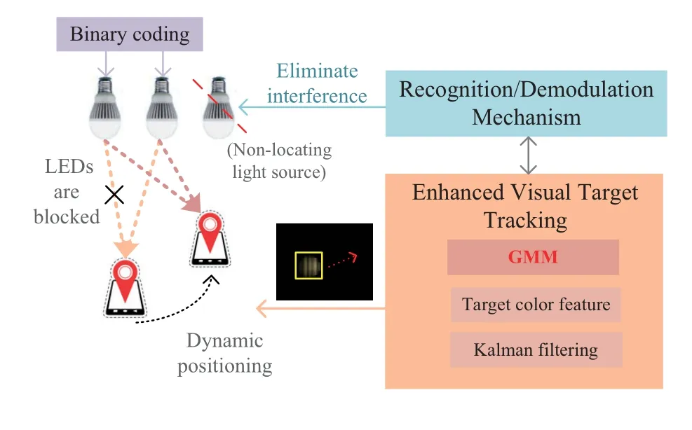
Figure 2.System overview.
2.2 Design Goals and Challenges
In this paper,we want to achieve two goals as follows:
• The positioning system can predict and track the accurate LED-ROI,when the captured LED disappears and the uncertain LED reappears.
• The positioning system can achieve highprecision positioning,when the smartphone is in stationary,low speed,fast speed,and variable speed status.
To achieve these goals,we face the following challenges:
• How to design the enhanced visual target tracking algorithm for the visible light positioning system to achieve comprehensive performance improvement among the positioning accuracy,real-time performance,and robustness.
III.LOCALIZATION BASICS
Here,we introduce the necessary technical knowledge for our enhanced visual target tracking algorithm.
3.1 Target Tracking Based on Color Feature
The conventional visible light positioning systems use continuous photographing and pixel-based ROI search methods to process captured images.A large amount of calculations greatly affects the system’s real-time performance.Therefore,we introduce the visual target tracking algorithm into our visible light positioning system,which uses small differences in target color features between two frames to accurately and quickly track LED-ROI.
Color space conversion and color histogram creation.When the smartphone captures the LED image in each video frame,the captured image is composed of RGB(red,green,and blue)color space.The RGB color space is sensitive to the change in the light intensity in the ambient environment.We convert RGB color space to HSV(hue,saturation,and value)color space,which has more intuitive color information and resistance to ambient light interference,as shown in Figure 3.
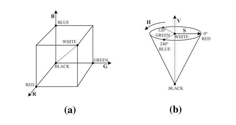
Figure 3.We use the HSV color space rather than RGB color space to resist ambient light interference. (a) RGB;(b)HSV.
Specifically,we first calculate the ∆value byR′=R/255,G′=G/255,andB′=B/255,as follows:
Then,we can getHcomponent,as follows:
After we transform RGB color space to HSV color space,we create theHcomponent color histogram for pixel coordinates{xi}(i=1,2,3,...,n)in the LEDROI.It is as follows:
According to the principle of the back-projection,we convert the color histogram into a visual grayscale image,which contains the color probability information of each pixel for the original image.
Iteration and LED tracking.We need the ROI centroid coordinates and ROI size to iterate the tracking window,for achieving the LED tracking.According to the newest ROI centroid coordinates and ROI size,we continuously adjust the tracking window size and update the tracking window center to the centroid coordinates so that we get the LED’s location and size in the current frame.Meanwhile,we revise tracking window parameters in real-time.
For the ROI centroid coordinates and ROI size(width,height),we use the zero-order moment,firstorder moment,and second-order moment to obtain them.
The X-order moment is as follows:
whereI(x,y)is the pixel value of(x,y).Wheni=0 andj=0,Equation(4)represents the zero-order moment.Wheni=1/2 orj=1/2,Equation(4)represents the first/second-order moment.The ROI centroid coordinates is(xc,yc)=
We use parametersa=and,to calculate the widthw,heighth,and direction angleθof the ROI[19],as follow:
We iterate the tracking window in the current frame to achieve accurate tracking LED-ROI.Specifically,our system detects the position with the largest probability of the color probability information around the tracking window until the centroid convergence (the centroid offset of two adjacent operations is less than the setting threshold).Through the above processing,we can get tracking window parameters.
Finally,we iterate all the video frames and use tracking window parameters in the current frame as the initial value of the tracking window in the next frame,so as to achieve the LED tracking in the video sequence.
3.2 Predictive ROI–Kalman Filtering
In most visible light positioning systems,when the light paths between the LED and receiver are blocked,the system can not achieve positioning.We introduce Kalman filtering to predict the LED-ROI in the current frame.
The Kalman filtering is divided into two steps,including the prediction and the correction.The prediction step is to estimate the current state based on the previous state,and the correction step is to synthesize the estimated state and observed state at the current time to estimate the optimal state[20].
For the prediction step:
For the correction step:
Equation(8)∼(12)are state prediction,error matrix prediction,Kalman gain calculation,state correction,and error matrix update,respectively.
In the visible light positioning system,the workflow of Kalman filtering is shown in Figure 4,and the steps are as follows:

Figure 4.The workflow of kalman filtering.
Step 1: Parameters initialization.We set the initial position,initial velocity,and error covariance ofxk-1state to zero.
Step 2: State prediction.We getxkstate and calculate error covariancePk.
Step 3: Location matching.We use the target position predicted byxkstate as the center search area to find the best matching position,and calculate the system measured value at timek.
Step 4: Calculation correction.We calculate the optimal estimated value through predictive value and measured value.
The Kalman filtering initialization requirements are relaxed.It can estimate the accurate LED-ROI,when the light paths are blocked.
3.3 Gaussian Mixture Model
When the receiver moves suddenly,captured images appear with the blurring effect so that the positioning system fails.The background subtraction method can detect and capture dynamic targets well,we introduce the background subtraction method based on the Gaussian mixture model into the visible light positioning system.
The camera captures the moving target in a fixed scene.The moving target is called the foreground(FG),and the fixed scene is called the background(BG).When we know nothing about feature information at timet,we assume that the pixel valuehas the same probability for FG or BG,that is,p(FG)=p(BG).In addition,we assume that the FG targets have a uniform distribution.We use the Bayesian decision factor to determine whether the pixel is FG or BG[21].
The Gaussian mixture model uses the training setχto estimate the background modelwhich depends on the distribution of the training set.In order to cope with sudden changes in the FG or BG,we choose a suitable time windowT,χT=,which updates the sample training set by adding new samples to replace old ones.
Another point we need to consider is that the sample setχTmay contain pixels in the FG area,we use a Gaussian mixture model withMdistributions to estimate,as shown in Figure 5.It is as follows[21]:
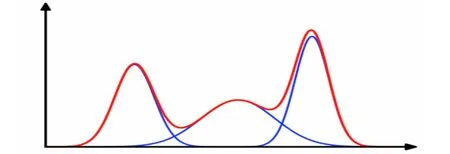
Figure 5.Gaussian mixture model with M distributions.
IV.POSITIONING BASED ON ENHANCED VISUAL TARGET TRACKING
In this section,we design the enhanced visual target tracking algorithm,which combines the above three methods to improve the system’s robustness.
4.1 Recognition/Demodulation Mechanism
In order to solve the problem that the visual target tracking algorithm may recognize the landmark in error,when the uncertain LED is reappearance.We design the lightweight recognition/demodulation mechanism to accurately track LED-ROI and quickly demodulate the landmark information.Specific mechanism steps are as follows:
Step 1: Preprocessing.We use Gaussian filtering to remove the noise on the video frame [22] and we perform grayscale and binarization operations on the LED image;
Step 2: Extracting LED-ROI.We sample the pixel intensity on the preprocessed LED image by the equidistant rows and columns,to extract the LEDROI;
Step 3: Demodulation.We find the midline of each LED-ROI to calculate the gray value of all points on this line,as follows:
whereR,G,andBrepresent red,green,and blue values ati-thpoint,respectively.According to the calculated gray value,we judge that this point is the bright stripe or the dark stripe.
We sort the abscissa of the starting point of all bright and dark stripes from small to large,so that we get the abscissa value of the starting point of each stripe.Further,we get each stripe width.We traverse the set of stripe widths to obtain the bright and dark stripe sequence.
Step 4: Matching.We match the bright and dark stripe sequence with LEDs in the database to determine whether the captured LED is a valid landmark light source.When the LED is blocked and reappears,if the LED-ROI is coincident with the tracking window predicted by the Kalman filtering,we will omit the extracting LED-ROI step(Step 2).
For the designed mechanism,the equidistant pixel intensity sampling avoids traversing all the pixels of the entire image,which decreases the image processing time consumption.Meanwhile,the mechanism also eliminates the possibility of the LED being wrongly judged,when the current LED is disappearance and the uncertain LED is appearance in the next frame.
4.2 GMM+Camshift+Kalman Filtering
The three methods mentioned in the previous section use a single feature for the target tracking.Each tracking method is suitable for a specific scene,which limits the application scene of the visible light positioning system.Therefore,we combine three methods to design an enhanced visual target tracking algorithm for improving the system’s comprehensive performance.
The enhanced visual target tracking algorithm considers four cases.
Case 1.Thesmartphoneisstationaryormovingat lowspeed.Ourtrackingwindowisdeterminedby thetargettrackingmethodbasedonthecolorfeature.Meanwhile,weusethetrackingwindowparametersof thepreviousframeasthewindowparameters’initial valuesinthecurrentframe,andweconstantlyupdate Kalmanfilteringparameters.
Case 2.Thesmartphoneisatvariablespeedandthe accelerationishigh.Ourtrackingwindowismainly determinedbythebackgroundsubtractionmethod basedontheGaussianmixturemodel.
Case 3.TheLEDisblockedindifferentextents.Both thetargettrackingmethodbasedoncolorfeature andthebackgroundsubtractionmethodbasedonthe Gaussianmixturemodelfail.Weusethepredictive valueoftheKalmanfilteringtoobtaintheLED-ROI inthecurrentframe.
Case 4.WhentheLEDdisappearsinthevideoframe andtheuncertainLEDappears,weusetherecognition/demodulationmechanismtojudgetheLED.Ifthe LEDistemporarilyblockedandreappears,theLEDROIcoincideswiththetrackingwindowpredictedby theKalmanfilter,wewilldirectlydemodulateandmatchit.Otherwise,weneedtoreinitializetheLEDROIandcontinuetrackingtheLED.
In summary,the workflow of the enhanced visual target tracking algorithm is shown in Figure 6,and the steps are as follows:
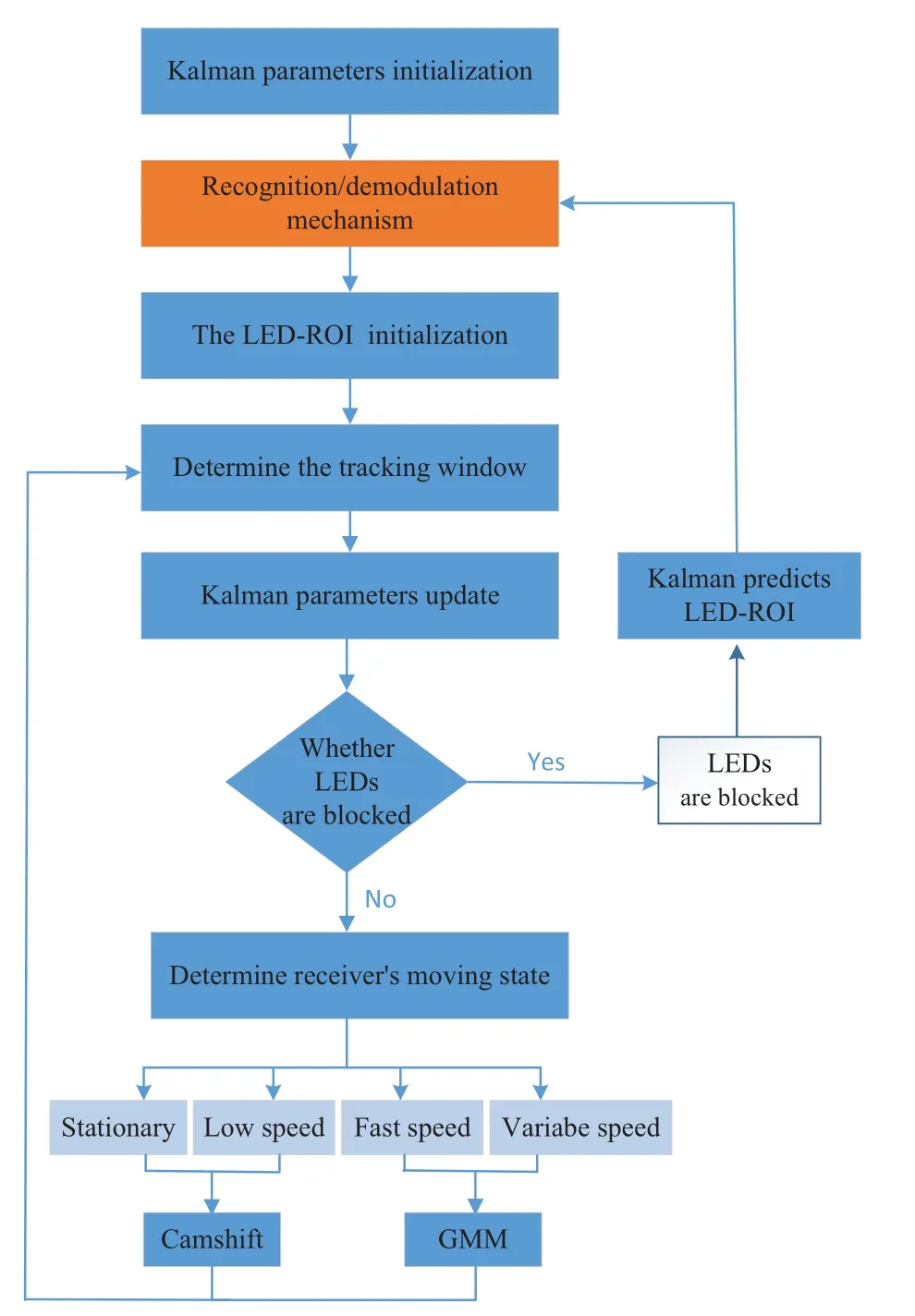
Figure 6.The workflow of our enhanced target tracking algorithm.
Step 1: Kalman filtering parameters initialization.We set all initial values including position,velocity,and error covariance to zero.
Step 2: The LED-ROI initialization.We use the recognition/demodulation mechanism to determine and track the LED and create the color histogram of the LED-ROI.When the LED is temporarily blocked and reappears in the video sequence,we directly deal with LED-ROI predicted by Kalman filtering without the ROI extraction processing.
Step 3: Coping with the situation where the LED is blocked in different extents.We compare the similarity between the histogram of the tracking window in the current frame and the color histogram of the target area in the first frame.When the similarity coefficient of the two histograms is less than the setting threshold,we think the LED is blocked.The predictive value of the Kalman filtering in the previous frame is used as the target area parameter in the current frame.We skip to Step 2,until the new LED appears in the video sequence.
Step 4: Determining the target tracking window.We use the target tracking method based on the color feature and the background subtraction method based on the Gaussian mixture model to obtain the tracking window.The weights of the two methods are determined according to the LED change status in the captured video sequence.
4.3 Positioning Calculations
Each LED has a unique world coordinate.We use the smartphone’s front camera to receive video frames with LEDs and deal with bright and dark stripes to get the landmark information.
We show the positioning principle of our system is as shown in Figure 7.In the world coordinate system,Pis to be solved positioning point,and the world coordinates are (X,Y).The world coordinates of the center points of LED-A and LED-B on the ceiling are(XA,YA)and(XB,YB)respectively.The distance between two LEDs isS1.
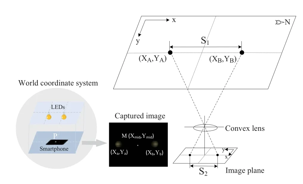
Figure 7.The positioning principle of our system.
In the camera coordinate system,Mis the center point of the captured image,and its camera coordinates are(Xmid,Ymid).The center points coordinates for LED-A and LED-B captured by the camera are(Xa,Ya)and(Xb,Yb),respectively.The distance between the center points isS2in the camera coordinate system.There is a mapping relationship betweenPandM.
Finally,we use computer vision,pinhole imaging,and geometric principles to get the smartphone world coordinates,details are presented in[23].
V.IMPLEMENTATION
In this section,we introduce our system hardware and software architecture.
5.1 Hardware Architecture
In our visible light positioning system,we useCXA1512 model LED as the light source,as shown in Figure 9a.Its power is 21.6W,which can provide enough lighting.We use Cyclone IV EP4CE6F field programmable gate array (FPGA) as the system microcontroller to program transmitted binary signals.In addition,we design the drive circuit to solve the insufficient voltage problem of the FPGA pin.The core of the drive circuit module is the IRF520 metal oxide semiconductor (MOS) transistor,which can quickly switch high levels and low levels.The receiver uses the googlepixelsmartphone with the Android operating system,as shown in Figure 9b.
5.2 Software Architecture
We show the software architecture of the visible light positioning system,as shown in Figure 8.The software architecture is divided into the following modules:
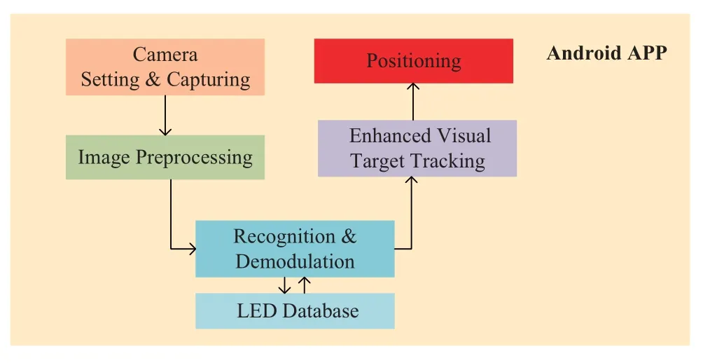
Figure 8.The software architecture of our designed system.
• Camera module:It is used to set the camera exposure time and ISO,in order to capture bright and dark stripes formed by LED.
• Image preprocessing module: It includes the binarization,grayscale,contour extraction,and color space conversion.
• Enhanced visual target tracking module:It is used to read the video frames and find the LED-ROI in each frame.
• LED database module:It contains the binary coding information and world coordinates of each LED.
• Recognition and demodulation module: It is used to demodulate the signal information in the ROI and match the corresponding LED.
• Positioning module: It is used to calculate the world coordinates of the receiver through camera photogrammetry.
VI.EVALUATION
In this section,we evaluate our visible light positioning system on different aspects including decoding rate,real-time performance,target tracking performance,and positioning accuracy.We name the system we designed as the Dsys,which is convenient for us to compare with other systems.
We measure the system performance on some metrics.
• Decoding rate: the ratio of the number of correctly decoded bits to the total number of transmitted bits from each LED.
• Positioning accuracy: the difference between coordinates calculated by our system and measured world coordinates.
6.1 Experiment Setup
The experiment parameters for the positioning system are shown in Table 1.We install nine LEDs on the 3.3×3.15m2ceiling,and the diameter of each LED lampshade is 19cm,as shown in Figure 9c.We invite different participants to conduct experimental tests so that the distance between the LED and the smartphone is between 0.5m-2.5m.We use the smartphone as the positioning receiver to record the video information,which can be used to achieve dynamic positioning.Our experiment is divided into the static(fixed point)test and the dynamic test.In the static test,we use a tripod to fix the smartphone.In the dynamic test,we use the speed-controllable smart car equipped with the receiver to precisely control the receiver moving speed.
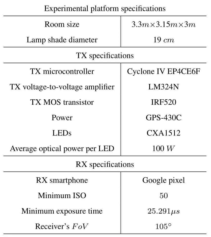
Table 1.Experiment parameters.

Figure 9.The hardware architecture of our designed system. (a)driving circuits;(b)smartphone as the receiver;(c)LEDs layout.
6.2 Tracking Effect in LED-ROI
We test the tracking effect in LED-ROI,by blocking LED in different extents and changing the receiver’s moving status.
In Figure 10,we show the LED tracking effect,when the LED is blocked in different extents.In Figure 10a,the LED is not blocked.In Figure 10b,Figure 10c,and Figure 10d,we use the shading plate to block the light path between the LED and the smartphone,so that the captured images appear“3/4 LED”,“1/2 LED”,and “no LED”,respectively.From the above Figures we can see that,when the light source is blocked to different extents,the Kalman filtering in the designed enhanced visual target tracking algorithm can accurately predict the LED-ROI(track the LED).

Figure 10.We show the LED tracking effect,when the LED is blocked in different extents. (a) no blocking;(b) quarter blocking;(c)one-half blocking;(d)completely blocking;(e)reappearing LED is the original LED;(f)reappearing LED is a new LED.
In Figure 10e and Figure 10f,we show the LED tracking effect,when the LED disappears and the uncertain LED appears.From Figure 10e and Figure 10f we can see that,the designed recognition/demodulation mechanism can accurately determine the landmark represented by the newest LED.
In Figure 11,we show the LED tracking effect with and without GMM,when the receiver is moving at different speeds.We randomly select a frame in the video sequence to observe the LED tracking effect.In Figure 11a and Figure 11b,the speed of the receiver is slower than 30cm/s,the images are the 13th frame with GMM and the 86th frame without GMM.In Figure 11c and Figure 11d,the speed of the receiver is 1m/s,the images are the 4th frame with GMM and the 7th frame without GMM.Similarly,in Figure 11e and Figure 11f,the 32th frame with GMM and the 54th frame without GMM are captured,the variable speed of the receiver is between 30cm/sand 1m/s.From the above Figures we can see that,our system with GMM can accurately track the LED regardless of the receiver’s moving status.

Figure 11.We show the LED tracking effect,when the receiver is moving at different speeds,with and without Gaussinan mixture model. (a)and(b)low speed;(c)and(d)fast speed;(e)and(f)variable speed.
6.3 Decoding Rate
We test the effect of the recognition/demodulation mechanism and communication distance on the system decoding rate.
In Figure 12,we show the effect of the recognition/demodulation mechanism on the decoding rate,when the receiver is under the dynamic test condition.We consider three cases: 1) The captured LED remains unchanged in the video sequence;2)The captured LED changes once in the video sequence,for example,LED-1 becomes LED-2;3)The captured LED changes two times in the video sequence,for example,LED-1 becomes LED-2 and then LED-3.From Figure 12 we can see that,the system decoding rate with recognition/demodulation mechanism is above 97%when the captured LED changes in the video sequence.The system decoding rate without the recognition/demodulation mechanism is lower than 40%so that the system can not recognize the landmark.It verifies that our recognition/demodulation mechanism makes up for the shortcomings that the conventional tracking algorithm can only track and cannot perform LED recognition and demodulation.
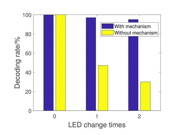
Figure 12.We show the effect of recognition/decoding mechanism on the decoding rate.
In Figure 13,we show the effect of the communication distance on the decoding rate.We randomly select 10 location points and test the decoding performance of each location point under different communication distances.We use the decoding average value of 10 points under the same communication distance as the decoding rate.From Figure 13 we can see that,the Dsys can reach almost 100%decoding rate,when the communication distance is 0.5m-2m.When the communication distance increases to 2.5m,the system decoding rate decreases significantly.At the normal handheld height,our system Dsys can meet the 100%decoding rate.
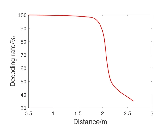
Figure 13.We show the effect of communication distances on the decoding rate.
6.4 Real-Time Performance
We test the real-time performance of the system according to the average processing time per frame.
In Table 2,we show and compare the average processing time per frame between Dsys and Ref.[23].We conduct five sets of experiments to measure the real-time performance of two systems.For each set of experiments,we record the consumption time of 1000 frames and get the average processing time per frame.

Table 2.Comparisons results on real-time performance.
From Table 2 we can see that,the average processing time per frame has a slight float for each system,which is caused by the blocked LED and the receiver at moving status.Compared with Ref.[23],the average processing time decreases 100ms.It shows that the real-time performance of Dsys is better than that of Ref.[23].
Further,in each frame,the time consumption includes the capturing video frame,image processing,and positioning calculations.In order to ensure the system’s stability,the Ref.[23] is required to update 1 to 2 times per second,the Dsys can update about 18 times per second.For the user experience,the Ref.[23]has obvious delay and freezing between the two positioning results,the Dsys behaves very smoothly and has good real-time performance.
6.5 Positioning Accuracy
We test and compare the system positioning accuracy between Dsys and Ref.[23] when the receiver is at stationary,low,fast,variable speeds,and the LED is blocked in different extents.
In Figure 14,we show the real world coordinates and the calculated positioning coordinates from two systems,under the static test condition.We use the laser rangefinder to measure the real world coordinates of the smartphone as the receiver.Then,we use the measured coordinates with the positioning coordinates calculated by two systems to get the system positioning error(accuracy).From Figure 14 we can see that,the average positioning errors of Dsys and Ref.[23]are 7.8cmand 7.2cm,respectively.
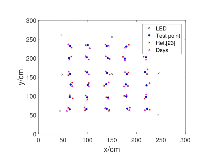
Figure 14.We show the system positioning accuracy,when the receiver is under static test condition.
In Figure 15,we plot the positioning coordinates distribution from Dsys and Ref.[23],under the low and fast speed conditions.The yellow line in Figure 15 represents the receiver’s moving trajectory.From Figure 15 we can see that,two systems have similar positioning accuracy,under the low and fast speed conditions.The positioning error between the real world coordinates and the calculated positioning coordinates for test points is 6cmto 12cm.
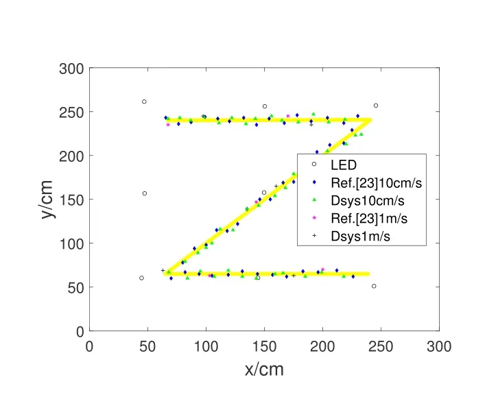
Figure 15.We show the system positioning accuracy,when the receiver is under the low and fast speed conditions.
In Figure 16,we plot the positioning coordinates distribution from Dsys,under the variable speed and blocking LED conditions.We do not show the positioning coordinates distribution for Ref.[23],because it cannot achieve positioning under the above conditions.From Figure 16 we can see that,the Dsys keep almost the same positioning accuracy between Figure 15 conditions and Figure 16 conditions.It shows that our enhanced visual target tracking algorithm can increase the system robustness,so that the system can achieve positioning under variable speed and blocking LED conditions.
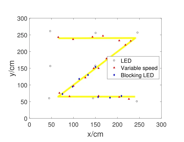
Figure 16.We show the system positioning accuracy,when the receiver is under the variable speed and blocking LED conditions.
In Figure 17,we plot the cumulative distribution function(CDF)curve of positioning accuracy for two systems,when the receiver is under low and fast speed conditions.From Figure 17 we can see that,the CDF curves of positioning accuracy for two systems are similar,the average system positioning error is 8cm.The positioning accuracy is at the sub-decimetre level.Under the variable speed and blocking LED conditions,our Dsys can still achieve robust positioning performance.
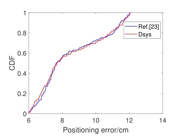
Figure 17.We show the cumulative distribution function curve of the system positioning accuracy.
6.6 Discussions
Here,we compare the comprehensive system performance between our Dsys and some similar related work.
In Table 3,we compare and evaluate the system performance including the positioning accuracy,real-time performance,experiment methods,and experiment conditions.Compare with Ref.[24] and Ref.[25],the Dsys behaves the similar positioning accuracy and much better real-time performance.Compare with Ref.[26],Ref.[27] and Ref.[16],the Dsys behaves the similar real-time performance and slightly inferior positioning accuracy.However,the Dsys uses the lightweight smartphone rather than the expensive camera and computer with high computing power.

Table 3.Comparison results on comprehensive system performance.
Meanwhile,for Ref.[24],Ref.[25] and Ref.[27],those systems only evaluate the positioning performance under static test conditions,without considering the dynamic test.For Ref.[26]and Ref.[16],two systems can evaluate the positioning performance under dynamic test condition.However,Ref.[26]cannot cope with the variable speed case and has the accumulated error from sensors.Ref.[16] cannot cope with the fast speed case due to the iterative ability limitation of the designed algorithm.
For our system Dsys,it can provide high-precision positioning when the receiver is under various moving statuses.
VII.RELATED WORK
In this section,we discuss the latest researches on visible light positioning and target tracking.
7.1 Visible Light Positioning
For the visible light positioning system,the light source and the receiver are essential components of the system.We divide the positioning system into the modified light source based system and the unmodified light source based system[28].
Modified light source system.Li et al.[29]proposed the Epsilon positioning system,which used binary frequency shift keying (BFSK) and channel hopping to enable multiple uncoordinated light sources to position and track the finger.Kuo et al.[30]proposed the Luxapose positioning system,which used modified light sources and the smartphone to achieve camerabased high-precision positioning.Liu et al.[31] proposed the lens-based positioning system,which used the spectral characteristics of convex lens to achieve a large number of light sensors positioning.Liu et al.[23] proposed the Dimloc positioning system,which used the novel image processing framework to deal with the blur effects from the dimming LED,and proposed the dual-LED positioning algorithm to achieve the high-precision system.Wang et al.[32]proposed the ALS-P positioning system,which used the characteristics of frequency aliasing to dynamically adjust the sampling rate of the ambient light sensor so that it could achieve high efficient LED decoding and light-weight positioning.Guan et al.[17]proposed the dynamic visible light positioning system,which used Camshift algorithm and Kalman filtering to track and detect transmitted landmarks.however,The proposed system ignored the possibility that the reappearing LED was another LED;The target detection algorithm was affected by the receiver’s moving status.
Unmodified light sources system.Yang et al.[24]proposed the PIXEL positioning system,which used polarization-based visible light communication to achieve a lightweight visible light positioning with good real-time.Zhao et al.[33] proposed the Navi-Light positioning system,which used a vector of multiple light intensity values sampled during the user’s movement as the system landmarks,for achieving the high-precision positioning.Konings et al.[34] proposed the FieldLight positioning system,which used the artificial potential field algorithm formed by a group of embedded photodiodes to position the receiver.Wang et al.[35] proposed the PassiveVLP system,which modified the reflective surface of the receiver and used the reflected light of the LED to achieve positioning.
These systems do not deal with the balance relationship among positioning accuracy,real-time performance,and robustness.In this paper,we use the enhanced visual target tracking algorithm to improve the real-time and robustness of the positioning system while ensuring positioning accuracy.
7.2 Visual Target Tracking
Next,we briefly introduce target tracking methods from the perspectives of background modeling,feature point,clustering,and supervised learning[36].
Background modeling.According to the target location change between two frames,Background modeling methods segment the foreground and the background for the image.They detect the target ROI,when the background is stationary and the target is moving [37].Weng et al.[38] proposed a novel frame difference method for moving target detection in a static background,which combined the three frame difference method and the background difference method.Chen et al.[39]proposed a novel background subtraction method based on layered superpixel segmentation,spanning tree,and optical flow,which had a good background subtraction effect.
Feature point.In these methods,each target represents its own identity information in the form of unique characteristics,including corners,spots,edges,nodes,and lines,for effective matching and recognition[40].Tareen et al.[41]showed that Scale Invariant Feature Transform(SIFT)and Binary Robust Invariant Scalable Keypoints (BRISK) were the most accurate methods,Oriented FAST and Rotated BRIEF (ORB)and BRISK were the most effective methods,through many comparative experiments.Li et al.[42] proposed a CNN-SURF Continuous Filtering and Matching (CSCFM) framework for indistinguishable object recognition or image retrieval.
Clustering.These methods refer to finding a collection of similar elements.Cheng et al.[43] proposed the mean shift algorithm,which was a continuous iterative method to find areas with dense data points based on sliding windows.Aguilar et al.[44]combined the easy convergence advantages of mean shift algorithm with the training method based on Haar-LBP features and Adaboost to improve the detector performance.
Supervised learning.These methods are based on target features for learning,classification,and recognition.The target features include gradient feature[45],pattern feature[46],shape feature[47]and color feature [48],etc.Girshick et al.[49] proposed the Regions with Convolutional Neural Network features model (R-CNN) for the target detection field.Girshick et al.[50] further proposed the Fast Regionbased Convolutional Network method (Fast R-CNN)model,which only extracted features from the detected image,to improve detection speed and detection accuracy.Google [51] used Slow network and Fast network to extract features of different frames to reduce computational redundancy and used Convolutional Long Short-Term (MemoryConvLSTM) features fusion to generate a detection frame for achieving real-time detection.
VIII.CONCLUSION
In this paper,we have proposed an enhanced visual target tracking algorithm to achieve the visible light positioning system with high comprehensive performance.First,we have proposed the lightweight recognition/demodulation mechanism,which eliminates the possibility of the LED being wrongly judged when the captured LED disappears and the uncertain LED reappears.Then,we have combined the Gaussian mixture model and LED color feature to enable the receiver to achieve positioning under various moving statuses.The experimental results have shown that our system can achieve comprehensive performance improvement among positioning accuracy,real-time performance,and robustness.
ACKNOWLEDGEMENT
This material is based upon work supported by the Guangdong Basic and Applied Basic Research Foundation No.2021A1515110958,National Natural Science Foundation of China No.62202215,SYLU introduced high-level talents scientific research support plan,Chongqing University Innovation Research Group(CXQT21019),and Chongqing Talents Project(CQYC201903048).Any opinions,findings,and conclusions or recommendations expressed in this material are those of the author(s) and do not necessarily reflect the views of the funding parties.
- China Communications的其它文章
- Learning-Based Dynamic Connectivity Maintenance for UAV-Assisted D2D Multicast Communication
- AIGC Scenario Analysis and Research on Technology Roadmap of Internet Industry Application
- Ultra Dense Satellite-Enabled 6G Networks: Resource Optimization and Interference Management
- Analysis and Optimization of Validation Procedure in Blockchain-Enhanced Wireless Resource Sharing and Transactions
- Anti-Jamming and Anti-Eavesdropping in A2G Communication System with Jittering UAV
- A Study of Ensemble Feature Selection and Adversarial Training for Malicious User Detection

