RIS Assisted Dual-Function Radar and Secure Communications Based on Frequency-Shifted Chirp Spread Spectrum Index Modulation
Xiaoping Jin ,Peng Zhang ,Chuan Wan,* ,Dingyou Ma ,Yudong Yao
1 Key Laboratory of Electromagnetic Wave Information Technology and Metrology of Zhejiang Province,College of Information Engineering,China Jiliang University,Hangzhou 310018,China
2 Key Laboratory of Universal Wireless Communications,Ministry of Education,School of Information and Communication Engineering,Beijing University of Posts and Telecommunications,Beijing 100876,China
3 Electrical and Computer Engineering Department,Stevens Institute of Technology,Hoboken,NJ 07030,USA
*The corresponding author,email: cwan_pawan@163.com
Abstract: Reconfigurable intelligent surface (RIS)assisted dual-function radar communications(DFRC)system is a promising integrated sensing and communication (ISAC) technology for future 6G.In this paper,we propose a scheme of RIS-assisted DFRC system based on frequency shifted chirp spread spectrum index modulation (RDFI) for secure communications.The proposed RDFI achieves the sensing and transmission of target location information in its radar and communication modes,respectively.In both modes,the frequency-shifted chirp spread spectrum index modulation (FSCSS-IM) signal is used as the baseband signal for radar and communications,so that the signal sent by the radar also carries information.This scheme implements the RIS-assisted beamforming in the communication mode through the azimuth information of the target acquired in the radar mode,so that the signal received from the eavesdropper is distorted in amplitude and phase.In addition,this paper analyzes the radar measurement accuracy and communication security of the FSCSS-IM signal using ambiguity function and secrecy rate (SR)analysis,respectively.Simulation results show that RDFI achieves both excellent bit error rate(BER)performance and physical layer security of communications.
Keywords: index modulation;secure communications;ISAC;DFRC;reconfigurable intelligent surface
I.INTRODUCTION
Chirp spread spectrum (CSS) technology [1] has been widely studied for its advantages of low power consumption,high reliability and long transmission distance in 5G mass machine-type communication(mMTC) scenarios.CSS is implemented based on linear chirp signal,which has good autocorrelation(AC) and excellent peak-to-mean envelope power ratio(PMEPR)properties which is initially most widely used in radar.In recent studies,CSS signals have been extended to frequency-shifted chirp spread spectrum(FSCSS)[2]signals to achieve the transmission of internet of things (IoT) information in LoRa communications.FSCSS signals are orthogonal and simple to implement in hardware,but have low spectral efficiency due to bandwidth and signal duration limitations.In the literature[3],the combinations of FSCSS signal are used as index entities for index modulation(IM) [4–9] and the FSCSS-IM scheme for communications is proposed,which achieves higher spectral efficiency with guaranteed bit-error-rate (BER) performance.However,in the CSS series schemes,longdistance communications raise concerns about physical layer communication security,which is not considered in the above schemes.
In multiple-input multiple-output(MIMO)communications,especially in the emerging sparse modulation [10],there are various ways to achieve secure communications,which include artificial noise (AN),beamforming techniques,etc.Among them,in ANbased IM schemes [11,12],the base station (BS)transmits AN orthogonal to the phase of the channel together with the message to the legal user.The AN based on the orthogonality design will not have any adverse effect on the received signal of the legal user.The noise at the eavesdropper will increase significantly and cause an error platform in the BER results.However,the energy utilization efficiency of this scheme is low because a portion of the transmit power is used to generate AN.While beamforming techniques change the directivity of the transmit beam by designing the weight vector of the antenna.The multipath signal transmitted by the MIMO antenna achieves in-phase superposition at the legal user and significantly improves the signal-to-noise ratio(SNR)at the receiver.The received signal at the eavesdropper is far lower than that of the legal user because of the non-inphase superposition,thus achieving secure communications.Based on this technique,directional modulation (DM) [13,14] has been proposed to achieve secure IM-based communications,and further improved communication security in extended schemes using orthogonal spread spectrum codes.However,these schemes face two challenges.One is the deep dependence on real-time updated a priori information about the target location or channel.Obtaining a priori information is a very consuming task in terms of the pilot overhead [15–17],especially in some complex communication environments,such as wireless communication involving reconfigurable intelligent surfaces(RIS)[18,19].Secondly,beamforming is implemented based on phased-array antennas,and the hardware cost for scheme implementation is high.
In order to obtain a priori information about the target position state and to realize the function of communication at the same time,an emerging dualfunction radar communication system(DFRC)[20]is used to realize the integrated sensing and communication (ISAC).DFRC technology can sense the distance,velocity,and azimuth of the target by the function of radar in addition to the function of communications.Compared with the traditional radar and communications separated scheme,the signal hardware module and spectrum resources can be shared between radar and communications.In addition,DFRC is easy to combine with other technologies.Among the schemes of ISAC,the DFRC scheme based on IM[21–23] is one of the schemes with the least mutual interference between communications and sensing information.In the next generation of communications,where sensing information has increasingly become an urgently needed resource,DFRC techniques will be increasingly applied.However,DFRC systems also require the deployment of phased-array antennas as well,which brings huge hardware cost overhead.In many studies on DFRC,RIS techniques[24–27]have been introduced to enhance the effect of beamforming.Compared with expensive phased-array antennas,RIS consists of many low-cost electromagnetic reflective elements that can change the amplitude and phase of the incident electromagnetic wave.RIS-assisted DFRC[24,25]achieves low hardware cost beamforming,which will be attractive and competitive in future IoT.
Based on the above background,a RIS-assisted dual-function radar and secure communications system based on FSCSS-IM(RDFI)scheme is presented.The work and contributions of the paper are summarized as follows.
•A novel DFRC framework is proposed to use the FSCSS-IM signal as the baseband signal for both radar and communications,thus achieving ISAC.
•In the proposed system,the radar assumes the work of communication line-of-sight channel estimation by means of angle estimation,thus assisting the design of beamforming and achieving secure communications.
•The performance of FSCSS-IM in DFRC in radar and communications is analyzed,respectively.The analysis of target position information measurement accuracy performance of radar are given by ambiguous functions.The analysis of the security performance of communications are given by the secrecy rate(SR).
The rest of this paper is organized as follows.This paper first presents the system model in Section II.Next,the ambiguity function and the SR of the system are analyzed in Section III.In Section IV,we discuss the numerical simulation results and explore some issues related to the proposed scheme and the system.Finally,Section V concludes the paper.
Notation: Bold lowercase and bold uppercase letter denote vectors and matrices,respectively.The symbols (·)Tand (·)Hrepresent transpose and Hermitian transpose operators,respectively.(·)∗denotes the conjugate operator.1 denotes a matrix with all elements being 1.The symbol∥A∥Frepresents the Frobenius norm of the matrixA.The symbols Tr(A) denote the trace of matrixA.diag(A) is a function that stacks the elements of the vectorAinto a diagonal matrix.The symbol|·|indicates the absolute value operation.CN(0,σ2)indicates the distribution of circularly symmetric complex Gaussian random variables with mean zero and varianceσ2.CM×Ndenotes the complex number field ofM×N.is the complex number symbol.denotes the binomial coefficients andindicates the floor operations.Finally,Re{A}denotes the real part ofA.
II.SYSTEM MODEL
In this section,we specifically introduce the proposed RDFI system for secure communications.In Subsection 2.1,we introduce the proposed framework of the RDFI system.In Subsection 2.2,we introduce the construction methods of the FSCSS-IM signal in the radar and communications mode respectively.In Subsection 2.3,we explain the radar mode.In Subsection 2.4,the joint beamforming is designed for secure communications.In Subsection 2.5,we explain communications mode.
2.1 RDFI System
A radar and communications collaboration method proposed in this proposal will be implemented by the RDFI system designed in this paper.The RDFI system is designed as a co-located MIMO radar communications system,and the installed antenna array in BS works as both a transmitter and receiver for the radar,and as a transmitter for the communications.RDFI can be deployed in traditional BS,road side units (RSU)and other communications or sensing scenarios.It is used to detect the location status information of static or low-speed moving targets and send downlink communications information to legal users Bob.
Figure 1 depicts the RDFI system model we designed.The transmitter Alice sends communications signals only to the unique legal user Bob,and the eavesdropper Eve outside the detection range of radar is trying to eavesdrop on the legal user Bob’s message.The number of receiver antennas at Bob and Eve areNB=1 andNE=1,respectively.The RDFI BS at Alice is equipped with a uniform linear array(ULA),which consists ofNAantennas with distancedbetween units.The communications and radar share the antenna array with each other,and the carrier wavelength isλ.RDFI can achieve different functions,including radar mode and communications mode.The target location status information of the legal user needs to be sensed by radar before transmitting the communications information each time.
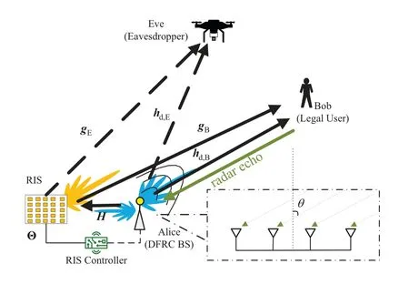
Figure 1.RDFI system model.
A RIS withNRunits is deployed near the RDFI BS to assist radar and communications.In order to make the received signal of the radar only the echo from the target,the RIS is activated in the following way: In the communications mode,the RIS is all active;in the radar mode,the RIS is active when the radar transmits a signal and is off when the radar does not transmit a signal.
A proposed RIS-assisted DFRC [24,25] as shown in Figure 1,the transmission signal of radar and communications pass through two paths “Alice-Bob” and“Alice-RIS-Bob” if it is to be transmitted from Alice to Bob.Where “Alice-Bob” is the direct path,denoted ashd,B∈.In the“Alice-RIS-Bob”path,gB∈denotes the direct path channel between RIS and Bob,andH∈is the Rice fading channel[24]between Alice and RIS.
For ease of understanding,here we define the relationship between Alice,Bob and RIS directional angles as follows: the anglesθRB,θAR,θABare angles of departure(AOD).θABis the angle between the normal of Alice antenna array and Bob.Similarly,θRBis the angle between Bob and the RIS array normal,andθARthe angle between the RIS array normal and the Alice antenna array normal.The anglesθRA,θBAandθBRare the angles of arrival (AOA) of the signal for the array,in this system,θRA=θAR,θBA=θAB,θBR=θRB.
2.2 FSCSS-IM Signal
In this subsection,we first describe the baseband sampled signal used by the FSCSS-IM for transmitting in radar.This signal model is then represented in a simplified form as a communications symbol for FSCSSIM.The designed radar operates by transmitting a single radar pulse signal to achieve target detection.
The CSS signal commonly applied in pulse radar is represented in the time domain as
whereTris the pulse width of the CSS signal pulse.µis the linear tuning frequency of the chirp signal.rect(·) is the rectangular function.TheUorthogonal FSCSS signalfFSCSS(u,t)can be obtained by theu(u=1,2,...,U)equally spaced frequency shift in the above conventional chirp signalfCSS(t) with periodTr,which is expressed as
WhenLsignals are selected fromUFSCSS signals to be transmitted simultaneously,there arecombinations.Here we select thefromcombinations as the transmission entities for IM,i.e.,theQFSCSS-IM signals are generated.Define the set of numbered combinations of sent FSCSS signals asp,then the FSCSS-IM signalfFSCSS-IM(pq,t)can be expressed as
wherepqdenotes theq-th group number in the numbered combination setp.For example,whenU=6 andL=2,there are a total ofQ=8 FSCSS number combinations,i.e.p={{1,2},{1,3},...,{1,6},{2,3},...,{2,5}},and whenq=2,pq={1,3}.
If samplingfFSCSS(u,t) atn/U×Trin uniform spacing in time,n=1,2,...,U.µ=.The signal in Eq.(2)can be simplified as
Similarly,if samplingfFSCSS-IM(pq,t)atn/U×Trin uniform spacing in time,n=1,2,...,U.The signal in Eq.(3)can be simplified as
The sequence ofsq(n)can be represented as a vector form ofsq∈C1×U.In the communications mode,the continuous time signal of the FSCSS is modeled as a simpler set of discrete time series of communications codewords[3,28]chosen fromsq.
2.3 RDFI Radar Mode
This subsection specifically describes the implementation principle of the proposed radar mode for RDFI BS.In the radar mode,the RDFI BS can be considered as a co-located MIMO radar,where the antenna array is used to transmit radar signals and receive echo signals from the user target.
First,to transmit the information by FSCSS-IM,it is necessary to selectQsignals fromfFSCSS-IM(pq,t)as the codebook setS(t)={s1(t),s2(t),...,sQ(t)}of the radar transmit signal waveform,wheresq(t)=fFSCSS-IM(pq,t),q=1,2,...,Q.The bit stream of the radar mode input is grouped intoB1=log2(Q)bits per group,and the group of bits is used to select the transmit signalsq(t)fromS(t).
Here we set the RIS to be active only at the moment of transmission of the radar signal.Unless the BS and RIS are deployed in close enough proximity,there will be an overlap of the echo signals in both directions of the direct reflection path and the reflection path through the RIS,thus affecting the spatial spectrum of the echo signals.
As shown in Figure 1,the radar signals are transmitted through two paths in RIS assisted DFRC,“Alice-Bob-Alice” and “Alice-RIS-Bob-Alice”.The echo signal from Bob’s direction received at Alice consists of two parts,it can be represented as
whereαis the reflection factor of the user target,which is related to the radar cross section (RCS) of the target.sq(t-τ1) andsq(t-τ2) are the transmit signalssq(t)through time delayτ1andτ2respectively.τ1=is the delay of the signal through the“Alice-RIS-Bob-Alice”.cindicates speed of light.τ2=is the delay of the signal through the “Alice-Bob-Alice” path.ξABis the distance from Alice to Bob,ξRBis the distance from RIS to Bob,andξARis the distance from Alice to RIS.is the noise.When transmitting narrowband information,the difference in delay between the two paths of transmission is much smaller than the bandwidth.The Θ∈is the RIS reflection matrix,which is default set to an identity matrix in the radar mode.w∈CNA×1is the weight vector of the beamforming in the radar mode,and the default matrix elements are all set to 1/NA.ar(θBA) is the array response vector of the antenna array at Alice in the direction ofθBA,which can be formulated as
Hcan be expressed as
whereHLOSdenotes line-of-sight channel,andHNLOSindicates a non-line-of-sight channel.Kis the Rice factor of the Rice distribution.at(θAR)is the steering vector of the antenna array at Alice in theθAR,andar(θAR)is the response vector in the directionθAR,respectively.In addition,the channelhd,Bbetween Alice and Bob and the channelgBbetween Bob and RIS can be respectively expressed as
whereat(θAB)is the steering vector of the antenna array at Alice in the direction ofθAB,andar(θBA)=at(θAB).at(θRB) is the steering vector of the RIS array in the direction ofθRB.The above expressions forat(θAR),at(θAB),at(θRB) andar(θRA) can all be obtained by analogy with Eq.(7).
There are many methods for detecting the echoes of chirp signals,and these methods are also applicable to the proposed RDFI system,since the FSCSS-IM signal retains the characteristics of chirp.RDFI in radar mode can obtain azimuthby a variety of AOA estimation algorithms,here is an example of a multisignal classification(MUSIC)algorithm[29].Sampleto get.The estimated covarianceofis calculated as
Eigenvalue decomposition is performed on the covariance matrix.The signal subspaceZsqand noise subspacecan be determined after sorting the eigenvalues from smallest to largest,as follows
The spatial spectrumPMU(θ)of the signal is calculated as
where the directional angle corresponding to the highest value ofPMU(θ)is the estimated
SinceθARis fixed and known,can be calculated according to the geometric relationship of triangle.Correspondingly,the estimated channel matrices areandrespectively.
The target user Bob reflects the radar signal and generate an echo,while Bob receives the radar signal and detects the information carried therein.If the transmitted signalsq(t)is expressed as a vector formsq,the signal received at Bob after passing through the “Alice-Bob” path and the “Alice-RIS-Bob” path[24,25]can be expressed as
Then,by decoding the index of the transmitted signal obtained,the transmitted bit information can be recovered.
2.4 Joint Beamforming Design of BS Array and RIS for Secure Communications
The RDFI scheme proposed in this paper uses RIS to reinforce the beam with beamforming by superimposing the beam at the user to improve the channel gain,so that the radar signal received by the user in the directionis further enhanced.
The joint design of the beamforming weight vectorwand the RIS phase shift matrix Θ is considered.The purpose of the joint beamforming of the BS antenna array and the RIS array is to make the main lobe of the beam point to the legal user,while the eavesdropper is in the side lobe.As a result,the radar echo signal at the legal user will be significantly enhanced thus improving the detection capability of the radar.While the received SNR in the direction of the legal user will be significantly increased compared to the eavesdropper thus improving the communication BER performance and achieving secure communication.
Since the RIS can secondly adjust the phase of the signal after the beamforming process has been performed.The first consideration is to design thewto maximize the channel gainwof“Alice-Bob”path while satisfying the transmit power limitwHw=1,wis designed[13,14]as
Secondly,the phase regulation of RIS is needed to counteract the joint effect of the channelH,gBandwon the phase of the received signal in the RIS path.The signal passing through thev-th RIS element is affected by the phase shift of this element,but also receives the phase shift ofwandgv,hv,ljointly.Wheregvis thev-th element of the vectorgB=[g1,g2,...,gv,...gNR] andhv,lis thel-th column element of thev-th row ofH.wldenotes thel-th element ofw.v=1,2,...,NR.l=1,2,...,NA.
Thew,gvandhv,lhave a common effect on the phase.The phase shift of the signal when passing through the”Alice-RIS’sv-th unit-Bob”channel is
where Θvis thev-th element on the main diagonal of Θ.To maximize the channel gaingBΘHw,Θvis designed as
In this joint design,the phase shift after passing through the“Alice-Bob”channel is 0.The phase shift of the channel fading through each RIS unit on the“Alice-RIS’sv-th unit-Bob”path is also 0.This maximizes the total channel gain(hd,B+gBΘH)w.Then the signals will be superimposed in-phase at Bob and non-in-phase at Eva after passing through all paths.This results in a significantly better channel condition at Bob than at Eva,achieving a secure communication environment.
2.5 RDFI Communications Mode
This subsection will specify the implementation mechanism of the proposed RDFI BS communications mode.In this mode,the RDFI will exploit estimated Bob’s azimuthpreviously obtained by the radar to estimate a simple direct channel.By the method of beamforming,the legal user can receive the communications symbols correctly,while at the eavesdropper the signal will be scrambled[14].
Different from the FSCSS-IM scheme in LoRa[3],the chirp signal sent in the communications mode in this paper can carry the constellation symbol.While in previous radar mode,if the FSCSS-IM carried MPSK,it is possible to affect the azimuth estimation of some algorithms.RDFI divides the input bit stream of RDFI into groups in the communications mode.Each group containsB2=log2(Q)+log2(M) bits,log2(Q)bits are used to select the FSCSS-IM signalsqfrom theS={s1,s2,...,sQ}calculated by Eq.(5),and log2(M) bits are used to select the MPSK constellation symbolem,m=1,2,...,M).The transmit signalxi∈C1×U(i=1,2,...,QM) can be expressed as
The communications channel model set in this paper has been described in detail in subsection 2.1 to implement the secure communications.Among them,the channels of the signals of radar and communications reaching the legal user target are set to be the same,which is very common in the study of ISAC.The signals are transmitted to the user via the direct path channel of “Alice-Bob” and the reflecting path channel of “Alice-RIS-Bob”.The signal received at Bob can be expressed as
When the CSI of all paths is known at the Bob receiver,the ML detection can be implemented to decode the transmit signal index of FSCSS-IM by the following equation:
Since the FSCSS-IM signal retains the orthogonality [2] of FSCSS,noncoherent low-complexity (LC)detection can be achieved when the signal is received at the legal user.The eavesdropper Eve is unable to eavesdrop by this low-complexity decoding method.The index of the transmit signal of FSCSS-IM can be obtained from the following equation:
The complexity of the ML algorithm of Eq.(20)is,and the complexity of the LC algorithm of Eq.(21)isO(4U2).
The eavesdropper Eve is located at a different angle from Bob and eavesdrops on the BS’s transmitted signal in real time.The communications signal is transmitted from Alice to Eve through two paths:“Alice-Eve”and“Alice-RIS-Eve”,where“Alice-Eve”is the direct path,denoted ashd,E=at(θAE).In the“Alice-RIS-Eve” path,gE=at(θRE) represents the direct path channel between RIS and the eavesdropper Eve.The relationship of the directional angles between Alice,Bob and Eve are:θREandθAEare both departure angles,θREis defined as the angle between Eve and the normal of the RIS array,θAEis the angle between Eve and the normal of the Alice antenna array,θEAandθERare the arrival angles of the signal for the array,respectively.In this system,θEA=θAEandθER=θRE.
The signal received by the eavesdropper at directionθAEis represented as
After the transmission of the beamforming signal through the two channel paths,the signal received at Eve produces both amplitude and phase distortions.When the receiver decodes without using the CSI,the value of phase shift that occurs as the signal passes through the channel is not known,and thus the MPSK modulation symbols carried by the signal cannot be distinguished.So the eavesdropper can only decode it by the following ML detection:
The main advantage of the proposed RDFI is the significant improvement of the difference between the received SNR of legal users and eavesdroppers.In this way,directional physical layer security is achieved.
In this section,the collaboration of radar and communications described is shown in Figure 2.The location information of the legal user obtained from the radar measurements is used in the design of the joint beamforming of the BS antenna array and the RIS array,which enables secure communications.
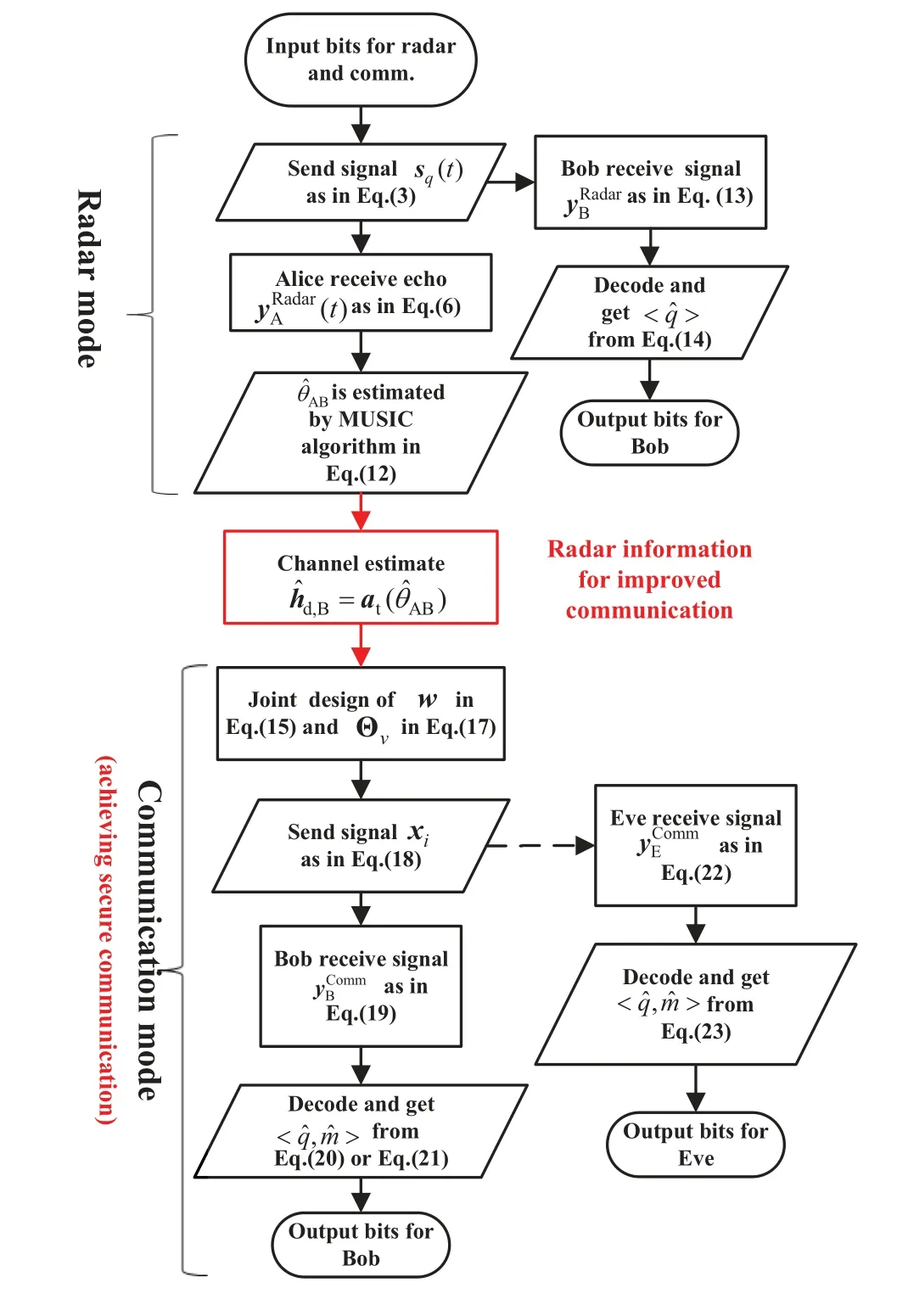
Figure 2.The radar and communication collaboration process for proposed RDFI system.
III.RADAR AMBIGUITY FUNCTION AND COMMUNICATIONS SECRECY RATE ANALYSIS
In this section,the impact on radar performance is analyzed when the FSCSS-IM signal is used as a radar baseband signal and the security performance of RISassisted beamforming for secure communications,respectively.Firstly,the discriminative ability of the FSCSS-IM signal for different target distances and velocities is qualitatively described by ambiguity functions in 3.1,corresponding to the simulation results in Section IV.The concept of SR is then introduced in 3.2 to characterize the security of communications mode.
3.1 Radar Ambiguity Function of FSCSS-IM Signal
Ambiguity function is an effective tool for analyzing radar waveform signals.By studying the ambiguity function,it is possible to analyze the ideal resolution,ambiguity,measurement accuracy and antiinterference capability of radar when transmitting a baseband signal of a specific waveform.Simply speaking,when there is a distance and velocity difference between the interfering target and the observed target,the numerical result of the ambiguity function can visually represent the degree of interference of the interfering target to the radar observation process.We focus on the two-dimensional ambiguity function,i.e.,the range-velocity ambiguity function,expressed as the correlation between the original waveform signal and the result of this signal after generating time delay and Doppler shift.
If an ideal“point target”is considered,the time delays of target 1 and target 2 are assumed to beτ0andτ0+τ,and the Doppler shifts arefd0andfd0+fd,respectively.The definition of the ambiguity function for the transmitted signals(t)is
The ambiguity function of FSCSS-IM can be obtained by substituting the FSCSS-IM signal of Eq.(3)intos(t)as
The integral term of the above equation is the ambiguity function of a single FSCSS-IM pulse,and there exists a unique frequency shift term,i.e.,fd-µτ.Then,the corresponding |χFSCSS-IM(τ,fd)| can be expressed as
3.2 Secrecy Rate Analysis
In the analysis of secure communications systems,the most primitive way to characterize the secrecy of communications is to use the difference in BER performance between legal users and eavesdroppers.However,this approach makes it difficult to achieve a specific quantification of communications security,and the computational space-time complexity of BER performance analysis via Monte Carlo experiments is high.Therefore,this paper considers the communications security of the proposed RDFI system by the method of SR analysis.The SRof a conventional communications system can be expressed as
wherep(yB,xi)andp(yB|xj)are conditional probabilities.Similarly,the mutual information of the eavesdropper on the corresponding channel can be expressed as
The above expressions need to calculate the mutual information based on a large amount of channel and noise data,which,in fact,will cause a large computational complexity.In this regard,we try to replace the treatment of mathematical statistics with the numerical value of the probability distribution of the noise.Inspired by [30],after calculating the instantaneous cut-off rate at the receiver,the mutual information can be approximated and derived as
Similarly,the mutual information of the eavesdropper on the corresponding channel can be expressed as
IV.SIMULATION RESULTS
In this section,we perform numerical performance simulation and evaluation of the RDFI system.Firstly,the Monte Carlo simulation of the RIS-assisted secure communications scheme proposed in subsection 2.5 is performed to analyze the BER performance of the system and the secure performance of the communications in Figure 3 and Figure 4.Secondly,Figure 5 shows the ambiguity function of the FSCSS-IM signal and compares it to the traditional CSS signal commonly used in radar.Finally,to verify the effectiveness of the radar sensing performance,Figure 6 presents the spatial spectrum estimation of the RIS-assisted MIMO radar in the radar mode.
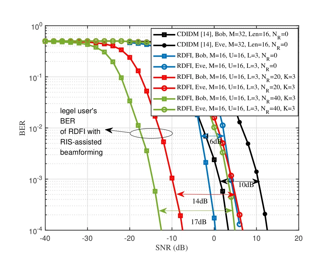
Figure 3.BER of different confidential communications schemes.
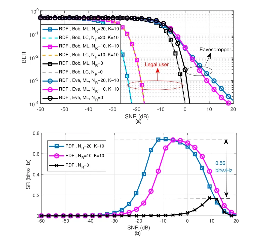
Figure 4.Illustrates the correspondence between BER and SR of RDFI.(a)BER performance. (b)SR performance.
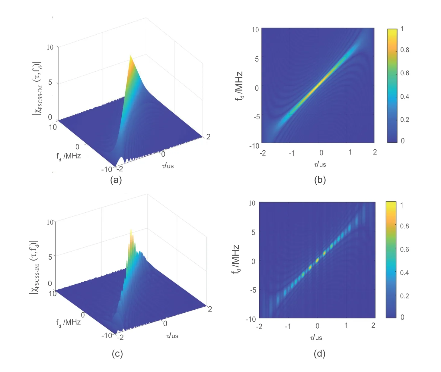
Figure 5.Ambiguity function of CSS signal and FSCSS-IM signal. (a) 3D plot of CSS. (b) 2D plot of CSS. (c) 3D plot of FSCSS-IM.(d)2D plot of FSCSS-IM.
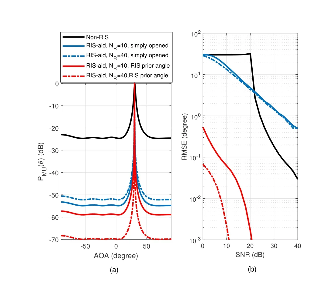
Figure 6.RMSE of spatial spectrum and AOA estimation error of RDFI using MUSIC algorithm.
In order to demonstrate the advantages of the proposed RDFI scheme in terms of both BER performance and secrecy performance in the communications mode,Figure 3 compares the performance of RDFI with that of the CDIDM scheme proposed in[14].The CDIDM scheme has only a direct channel between the BS and the legal user and the eavesdropper,and there is no channel reflected by the RIS,so it is set to beNR=0.Referring to the simulation location parameters set in [14],the azimuth of Bob’s location is set to beθAB=30◦and the azimuth of the eavesdropper is set to beθAE=60◦.The CDIDM uses Hadamard coding with code lengthLen=16 and MPSK modulation of orderM=32.In order to compare the same channel conditions with the same spectral efficiency,the antenna parameters for all schemes are set toNA=4,NB=NE=1,and the channel Rice factor isK=3,achieving a spectral efficiency ofR=0.8125 bit/s/Hz.In order to achieve the same spectral efficiency of CDIDM,parameters for generating RDFI FSSCS-IM signals are set asU=16,L=3,M=16.Figure 3 shows the BER performance of RDFI without RIS assistance and compared the BER performance results of CDIDM,which demonstrates that the BER performance of RDFI’s FSCSS-IM signals achieved are better than the CDIDM scheme with the same spectral efficiency.However,CDIDM has a communications secrecy SNR gain of 10 dB when BER drops to 10-4compared to 6 dB for RDFI.This is due to the fact that the Hadamard code in CDIDM has stricter orthogonality than FSCSS-IM,however,this orthogonality also severely limits the spectral efficiency of CDIDM,and the BER performance is inferior to RDFI with the same spectral efficiency.In addition,since RIS does not carry information,even if the beamforming is achieved assisted with RIS,it cannot improve the spectral efficiency of CDIDM,therefore CDIDM cannot balance spectrum efficiency and communications secrecy.In contrast,the communication secrecy of RDFI is improved with the assistance of RIS,and the secrecy SNR gains of 14 dB and 17 dB are achieved inNR=20 andNR=40 conditions,respectively.This is mainly reflected in the fact that the BER performance of the legal user is significantly improved with the increase ofNR,while the BER performance of the eavesdropper fails to be significantly improved.The transmitted signals are superimposed in phase with increasingNRon the signals transmitted from different RIS units and BS antennas at Bob,while the signals transmitted in the Eve direction cannot be superimposed in phase and undergo phase and amplitude distortions.The results consistent with our proposed concept of using beamforming to achieve secure communications.
Figure 4(a) and Figure 4(b) represent the BER and SR performance of RDFI atU=8,L=2,M=4 andK=10 respectively.Figure 4(a)shows the BER performance of the legal user Bob and the eavesdropper Eve atNR=0,10 and 20,respectively.The BER results in Figure 4(a)show that the advantage of legal users over eavesdroppers in terms of BER performance will increase asNRincreases.When the BER drops to 10-4,the performance of legal users is improved by 1 dB,34 dB,and 45 dB compared to eavesdroppers atNR=0,10,20,respectively.In addition,the LC detection algorithm indicated by the dashed line exhibits a performance almost close to that of the ML detection algorithm when legal user decodes.With the same simulation parameters,Figure 4(b) more directly characterizes the concept of security.For example,atNR=20,K=10,the BER of the legal user in Figure 4(a)starts to drop,and the SR in Figure 4(b)starts to rise.When the BER of the eavesdropper in Figure 4(a)also starts to drop,the security of the system starts to lose and the SR in Figure 4(b) starts to drop.In addition,RIS-assisted beamforming effectively improves the maximum achievable SR by 0.56 bit/s/Hz atNR=20 compared to atNR=0.The simulation results illustrate that the BER results match the theoretical value of SR and verify the correctness of SR.
Figure 5 simulates the ambiguity function of the CSS signal and the RDFI-transmitted FSCSS-IM signal,respectively,for qualitative evaluation.Figure 5(a) shows the simulation results of the ambiguity function |χCSS(τ,fd)|of CSS,and Figure 5(b) is a two-dimensional plot of Figure 5(a).Figure 5(c)shows the simulation results of the ambiguity function|χFSCSS-IM(τ,fd)|of FSCSS-IM,and Figure 5(d)is a two-dimensional plot of Figure 5(c).The simulation parameters set are as follows: the pulse width of the radar isTr=2 us,the sampling frequencyfs=30 MHz,and the reflection factorαis set to be 1.The number of antenna array elements of DFRC isNA=4.The parameters set for the FSCSS-IM signal areW=16,L=3.The results from the ambiguity function simulation show that even though the FSCSS-IM has the ability to carry information capability,the radar resolution of FSCSS-IM is not lower than that of CSS signal.The simulation results of the ambiguity function show that the CSS signal inevitably causes range-Doppler coupling effect,which is manifested by the fact that both present a knifeedge main lobe.Some points with lower peaks appear on the knife-edge main lobe of the FSCSS-IM signal,and the range-Doppler coupling is reduced at these positions.The amplitude of the FSCSS-IM ambiguity function is slightly reduced at all locations except the center point.The FSCSS-IM has the ability to carry information compared to the CSS signal,and the radar measurement accuracy has been improved slightly.In fact,FSCSS-IM superimposesLFSCSS signals with bandwidthBon the spectrum.Therefore,the actual bandwidth of the FSCSS-IM signal is betweenBand 2B.Compared with the CSS signal with bandwidthB,the improvement of radar measurement accuracy of FSCSS-IM is mainly due to occupying a larger bandwidth.The FSCSS-IM signal carries the communications signal without affecting the radar performance,since the FSCSS-IM signal retains the waveform characteristics of the CSS signal to a great extent.
The spatial spectrum estimation of the MUSIC algorithm is performed for the received signal in the DFRC radar mode in Figure 6(a),and the root mean square error (RMSE) of the AOA corresponding to the different schemes is given in Figure 6(b).Radar’s simulation parameters are set toNA=4,fs=32 MHz,B=10 MHz,Tr=8 usα=1,and SNR of the radar signal in Figure 6(a)is 20 dB.The parameters set for the FSCSS-IM signal areW=16,L=3.The angleθARand the radial distance between Alice and RIS are set to be 0◦and 4 m respectively;the angleθABbetween Bob and Alice is set to be 30◦and the radial distance is set to be 30 m.In the above simulation conditions,the results of the angle estimation of RDFI using MUSIC algorithm are compared separately,and the results of the simulation are the average of the results of 1×10⁵Monte Carlo experiments.The simulation results compare the spatial spectrum of radar signals with and without RIS-assisted DFRC system.The RIS-assisted DFRC system is divided into the“RIS simply opened” scheme and the “RIS prior angle”scheme.In the“RIS simply opened”scheme,the weight vectorwis set to beand the RIS reflection matrix Θ is set to be the unit matrix.In the “ RIS prior angle ” scheme,the result of the previous estimated radar angle=30.1◦is used as the a priori angle,andwand Θ are obtained by substitutinginto Eq.(15) and Eq.(17),respectively.The simulation results show that the spatial spectrum of the RIS-assisted DFRC system has a better spatial spectrum performance compared to the scheme without RIS assistance.This is mainly because RIS improves the channel gain of the radar.However,if the number of RIS units is simply increased,the measurement performance of AOA does not improve further with the increase ofNR.This is due to the fact that the signal passing through different RIS units occurs at the receiver and is not in-phase overlapped.The accuracy of the angle measurement can be improved by adjusting the beamforming based on the results of the previous angle measurement.Although thewand Θ do not achieve the equivalent phase of the channel to be exactly zero,the SNR of the radar signal arriving at the legal user target is still improved.
V.CONCLUSION
In this paper,a RIS assisted secure communications system for DFRC system is proposed.The baseband signals of radar and communications are unified as FSCSS-IM signals.The AOA information acquired in radar mode is used for the estimation of the simple direct channel,which is then used to assist in the design of the joint beamforming of the BS antenna array and the RIS.The ambiguity function of FSCSS-IM is analyzed to qualitatively evaluate the performance of radar.And the feasibility of the FSCSS-IM signal as a radar baseband signal is verified by Monte Carlo experiments,and the RMSE of AOA estimation is calculated.Simulation results show that the FSCSS-IM signal has the ability to carry information and does not have a large impact on the resolution of the radar compared to the conventional CSS signal.RDFI provides a high spatially directed secrecy gain for physical layer communication,and achieving excellent BER performance for communication.
ACKNOWLEDGEMENT
This work was supported by the National Science Fund for Young Scholars (Grant No.62201539),the Project of Innovation and Entrepreneurship Training for National Undergraduates (Grant No.202210356005)and the project of Zhejiang University Student Science and Technology Innovation Activity Plan (Grant No.2023R409055).Xiaoping Jin and Peng Zhang contributed equally to this work.They should be regarded as co-first authors.
- China Communications的其它文章
- SR-DCSK Cooperative Communication System with Code Index Modulation: A New Design for 6G New Radios
- Sparsity Modulation for 6G Communications
- Sparse Rev-Shift Coded Modulation with Novel Overhead Bound
- Reconfigurable Intelligent Surface-Based Hybrid Phase and Code Modulation for Symbiotic Radio
- Model-Driven Deep Learning for Massive Space-Domain Index Modulation MIMO Detection
- Modulation Recognition with Frequency Offset and Phase Offset over Multipath Channels

