Design and comparative analysis of self-propelling drill bit applied to deep-sea stratum drilling robot
Peihao ZHANG, Xingshuang LIN, Hao WANG, Jiawang CHEN,3, Zhenwei TIAN, Zixin WENG, Ziqiang REN, Peng ZHOU
Research Article
Design and comparative analysis of self-propelling drill bit applied to deep-sea stratum drilling robot

1Ocean College, Zhejiang University, Zhoushan 316021, China2Hainan Institute, Zhejiang University, Sanya 572025, China3The Engineering Research Center of Oceanic Sensing Technology and Equipment, Ministry of Education, Zhoushan 316000, China
Robotic subsea stratum drilling robot is a method for new subsea stratigraphic geological investigation and resource exploration. Resistance at the front end is the main source of resistance to the robot’s motion in the strata. Since there is no continuous and strong downward drilling force as in conventional drilling rigs, robot movement relies heavily on the drill bit to reduce the drilling resistance. In this study we propose a self-propelling drill bit that can discharge soil debris to provide propulsive force and reduce the resistance. The key parameter of the drill bit design, the spiral blade lead angle, was determined by theoretical analysis of the drill bit’s soil discharging effect. To verify the structural advantages of the self-propelling drill bit in reducing resistance, a comparative analysis with a conventional conical drill bit was conducted. The drilling process of both bits was simulated using finite element simulation at various rotation speeds, the penetration force and torque data of both drill bits were obtained, and tests prepared accordingly in subsea soil were conducted. The simulations and tests verified that the penetration force of the self-propelling drill bit was lower than that of the conventional conical drill bit. The self-propelling drill bit can reduce the resistance effectively, and may play an important role in the stratum movement of drilling robots.
Subsea stratum investigation; Stratum drilling robot; Self-propelling drill bit; Penetration resistance
1 Introduction
Natural gas hydrate is an important energy source, with huge reserves worldwide. In the last decade, subsea natural gas hydrates have attracted attention due to their broad energy prospects (Dai et al., 2008; Zhu et al., 2017). However, changes in reservoir conditions due to excavation during the exploitation of subsea gas hydrates, will lead to destabilization and uncontrollable release of natural gas hydrate. This can cause marine geological disasters such as subsea landslides or changes in subsea topography, and has serious damaging environmental effects (McConnell et al., 2012; León et al., 2021). Because of the complexity and unknown condition of the seabed environment, there is no mature real-time monitoring equipment or technology that can be directly operated in a hydrate trial area to carry out environmental monitoring. Therefore, developing a new tool for monitoring the geological conditions of subsea sediment strata, such as a deep-sea stratum drilling robot, is imperative.
Autonomous excavation/drilling robots were first used in planetary exploration activities. These include screw-type robots, such as the screw subsurface explorer and digbot, which perform low-torque drilling using rotating screws through their screw blades' mechanical structure (Nagaoka et al., 2009; Abe et al., 2010; Becker et al., 2016). There are also bioinspired robots, including the mole-type drilling robot and the inchworm deep drilling system (IDDS). Bionic excavation is achieved through the cooperation of the drill bit and other bionic structures (Rafeek et al., 2001; Kubota et al., 2005). With the development of exploration robots, researchers have studied robots applied to subsea exploration, such as RoboClam from Massachusetts Institute of Technology (MIT) in the USA and the SEAVO series from Chuo University in Japan. RoboClam is a bionic robot inspired by the Atlantic razor clam that moves through soft soil by rapidly expanding its body structure (Dorsch and Winter, 2014; Winter et al., 2014). The Seavo robot from Chuo University is a bionic robot inspired by earthworms, which uses artificial muscle as a support mechanism to work with the drilling mechanism to complete the movement in the seabed stratum (Tadami et al., 2017; Isaka et al., 2019). However, since this is a new research field, none of these robots has yet completed sea trials or been deployed on the seabed.
Conical drill bits can provide good reaming and reduce resistance in soft soil environments. Researchers at the Japan Aerospace Exploration Agency (JAXA) analyzed the relationship between drilling speed, rotation speed, and penetration resistance of a conical drill bit by testing in dry sand and fly ash (Nagaoka et al., 2008, 2009). Through tests of a regolith simulant, researchers at the Harbin Institute of Technology, China, found that the inchworm boring robot could penetrate easily when the penetration rate (penetration speed/rotation speed) of the conical drill bit was no greater than 0.33 (Tang et al., 2015).
In terms of theoretical and simulation analyses of screw blades, Zhang and Kushwaha (1995) developed a modified theoretical model based on the McKyes-Ali model to calculate the cutting resistance of screw blade rotation. Finite element method (FEM) and MATLAB simulations were used to study the torque and penetration force of the screw blades and the relationship between torque and depth (Livneh and El Naggar, 2008; Zheng et al., 2013). The FEM is suitable for analyzing the interaction problem between soil and a drill bit, and the coupling Euler-Lagrange (CEL) method for analyzing large soil deformation in engineering (Chen, 2016).
In particular, the CEL method is very effective in simulating the large deformation and material flow problems of meshes caused by the pile penetration and tunnel boring machine excavation process in clay soil. Results show good agreement with test data (Qiu et al., 2009, 2011; Zhang et al., 2018; Kim, 2021).
In this study, a deep-sea stratum drilling robot and a screw-type self-propelling drill bit were designed, and a theoretical model analysis of the self-propelling drill bit was carried out. Furthermore, the deformation of the surrounding soil caused by the drill bit was determined through theoretical analysis. The disturbances caused by the self-propelling drill bit and a conventional conical drill bit were compared through FEM simulation analysis. A comparative analysis of torque and drilling resistance of the two drill bits was also conducted in an artificially prepared seabed soil test to verify the performance advantages of the self-propelling drill bit that can be applied to this low-disturbance and low-forward-resistance scenario for deep-sea stratum drilling robots.
2 Design of the deep-sea stratum drilling robot and the self-propelling drill bit
2.1 Structural design of the deep-sea stratum drilling robot
The drilling robot was applied to the subsea sediment gas hydrate trial area at a depth of more than 1500 m (Soloviev and Ginsburg, 1994). The structure of the deep-sea stratum drilling robot is shown in Fig. 1. It comprises five units: a drill bit unit, front supporting-anchor unit, steering unit, propulsion unit, and a rear supporting-anchor unit. In addition, anti-rotation plates are installed on the supporting-anchor unit of the robot to prevent its rotation during drilling. The modular structure of the robot provides high compatibility and interchangeability. To adapt to different working stratum environments, supporting-anchor and propulsion units can be added.
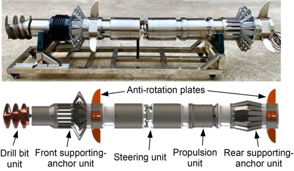
Fig. 1 Prototype and 3D structure of the deep-sea drilling robot
During the drilling process, the drill bit excavates the seabed soil and makes space for locomotion. Through the periodic cooperation of the front and rear supporting-anchor units and the propulsion unit, the robot can make peristaltic moves in the seabed, guided by the steering unit. The supporting-anchor unit inserts into the soil through expansion to support the robot's forward movement. The movement of the propulsion unit can effectively avoid the influence of soil pressure when the supporting-anchor unit is contracted. The locomotion principle of the robot is shown in Fig. 2 (Tian et al., 2021).
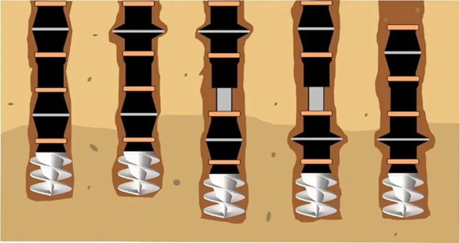
Fig. 2 Motion process of the stratum drilling robot
2.2 Analysis of the drill bit motion process
The drill bit is driven by a hydraulic motor located in the front unit cylinder of the robot, which provides the cutting force and torque required. Since the role of the drill bit in the drilling process is to reduce the penetration resistance and avoid large disturbance of the surrounding soil, the drill bit should be designed to meet the following functions: excavation of the front soil; backwards discharging of soil debris to reinforce the borehole.
The drill bit consists of a conical rod and constant pitch spiral blades, and the front end of the bit is a cutting edge with a certain angle. The drilling process of the bit is shown in Fig. 3a. The drilling motion consists of three specific actions on the soil: cutting sediment soil, transportation of fore soil, and discharging soil debris.
(1) The cutting edge of the drill bit cuts the front consolidated soil and breaks it into debris. The cutting process can be equated to a fixed-angle rotary cutting with a straight edge.

(3) While the spiral blades transport the soil debris upward, the conical rod squeezes the soil out laterally. Since the cutting edge and spiral blade diameter are comparable to those of the robot body, the soil at the front can be completely cut and transported, creating a borehole roughly equivalent to the drill bit's diameter.
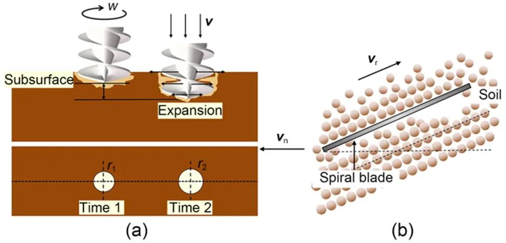
Fig. 3 Schematic diagram of the drilling process and drill bit: (a) drilling process; (b) soil debris transportation. is the angular velocity, v is the drilling speed, r1 and r2 are the borehole diameters of time 1 and time 2, respectively, vr is the vector velocity along the blade direction, and vn is the vector velocity of the soil unit in the horizontal direction
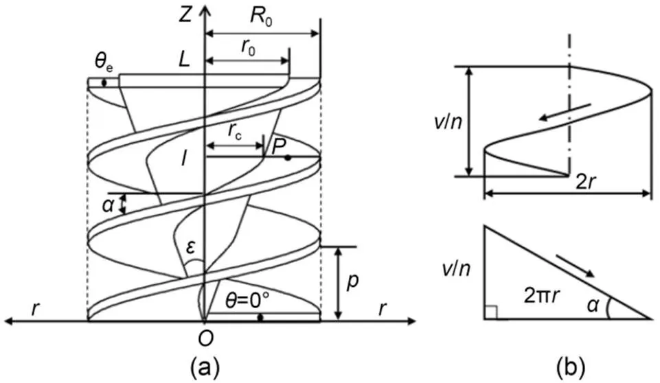
Fig. 4 Geometric model of the self-propelling screw drill bit: (a) geometric model diagram; (b) spiral unfolding diagram. is the spiral angle at any point on the blade, L is the hight of drill bit in Z axis, and n is the number of spirals
2.3 Design and parameter analysis of the drill bit


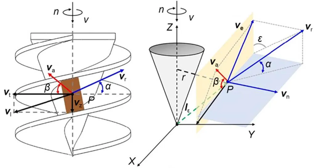
Fig. 5 Model of soil debris unit movement. is the distance between the soil unit and the drill bit's tip
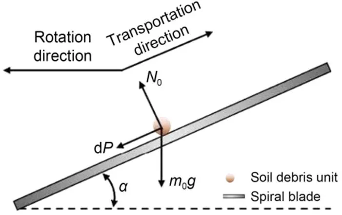
Fig. 6 Schematic of the force of soil debris unit movement

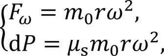
With the soil debris in steady motion, the unit is in force equilibrium, and decomposing the force on the unit into theandaxes gives (Lebedev, 2011):

Combining Eqs. (3) and (4) gives:


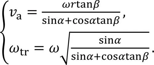


The speed of transport of soil debris by the drill bit can be calculated from the moving lead angle and the soil unit's absolute angular velocity . We chose =0.35 and =0.3 to plot the variation relationship between the drill bit rotation speed and the spiral blade lead angle at different values of the moving lead angle (Fig. 7). At the same spiral blade lead angle , increasing the rotation speed increases the soil moving lead angle, and the transport speed of the soil debris increases. At the same rotation speed, the maximum moving lead angle or soil transport speed can be obtained at a specific spiral blade lead angle. We also conclude from Fig. 7 that when the lead angle of the spiral blade is small, a high rotational speed is required to achieve soil debris transport or discharging, and too large an angle may render the soil transport function ineffective, i.e., the soil cannot move upward along the spiral blade.

3 Comparison of drill bits based on finite element simulation
3.1 Design of the simulation
To achieve the working effect and design advantages of the self-propelling screw drill bit (S-type bit) visually, FEM was used to simulate and analyze the drilling process. The plastic strain level and influence range on the surrounding soil caused by the bit's movement were observed through visualization results. A conventional conical drill bit (C-type bit) with a similar volume and size to the S-type bit was set up for comparison. A C-type bit is frequently used for reducing penetration resistance and has been used in a variety of drilling robots. The advantages of the S-type bit in reducing penetration resistance were revealed by comparing the penetrating force and torque.
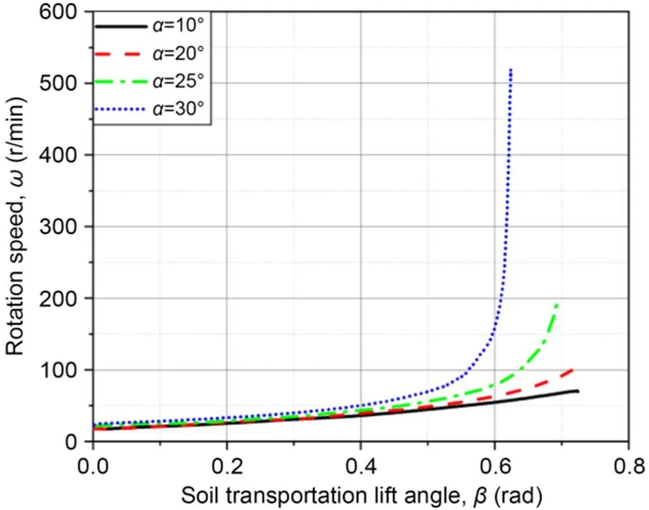
Fig. 8 Curves of the rotation speed and soil transportation lead angle
In the simulation, the CEL method was used because the drill bit causes large deformation of the meshes. Lagrange and Eulerian elements were used to discretize the drill bit and soil domain, respectively. The Eulerian mesh can be void domain, or part or all of it can be occupied by more than one material, and its volume fraction represents the part of the mesh filled with a specific material. The S-type bit has a blade diameter of 180 mm, length of 180 mm, drill rod cone angle of 40°, and spiral blade pitch of 120 mm. To exclude other influencing factors in the comparison as much as possible, the C-type bit had the same spiral blade pitch and drill rod size as the S-type bit. The spiral blade, which plays the main role in transporting soil, differs between the two types of bits. The C-type bit has conical spiral blades, the cone angle is the same as that of the conical drill rod, but the maximum diameter is the same as that of the S-type bit. To minimize the influence of the container boundary on the simulation process, a columnar soil of 800 mm in diameter and 1000 mm in height was selected to simulate the drilled seabed soil. To avoid extrusion of the Eulerian elements, a 200-mm void field was arranged above the soil material part. The mesh density of the range within 400-mm diameter was twice that of the outer area, and the mesh consisted of linear block units C3D8R with eight nodes. The detailed meshing and material distribution are shown in Fig. 9. Since the interaction forces between the drill bit and the soil were the focus of this numerical simulation, the stress path and the trend of the strain over time could be ignored. Meanwhile, to be more consistent with engineering applications and the characteristics of the Abaqus/Explicit analysis, the soil material was given elastic and Mohr-Coulomb plasticity material characteristics that obey Mohr-Coulomb yielding criteria.
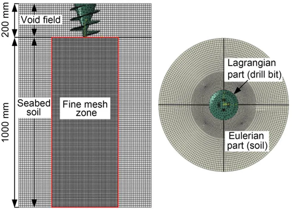
Fig. 9 Meshes of S-type bit drilling simulation used in CEL analysis
The soil material's base and sides were fixed, and it was assigned a predefined field of geostatic stress to balance additional strain caused by gravity. By means of a reference point bound to a rigid body drill bit, different rotation speeds and downward penetration speeds were applied to the drill bit as a whole. The penetration force and torque of the drilling process were obtained through the reference point after the drill bit reached the specified depth. The material parameters and motion parameters are shown in Table 1.
3.2 Results and analysis
The drilling speed of both drills was chosen as 20 mm/s, which is reasonable as the drilling robot moves in a peristaltic motion. The soil disturbance and stress caused by both drill bits were analyzed at three rotation speeds. Fig. 10 shows the volume-averaged stress at 60 and 180 r/min for each type of bit. The soil stress caused by the drill bit decreased as the speed increased. The ranges of soil stress response induced by the S-type bit were 2.0 and 1.6 times the maximum drill bit diameter at 60 and 180 r/min, respectively. The corresponding values induced by the C-type bit were 2.6 and 2.2 times. The same results were achieved at all three speeds, so only the 60 and 180 r/min results are shown in Fig. 10.
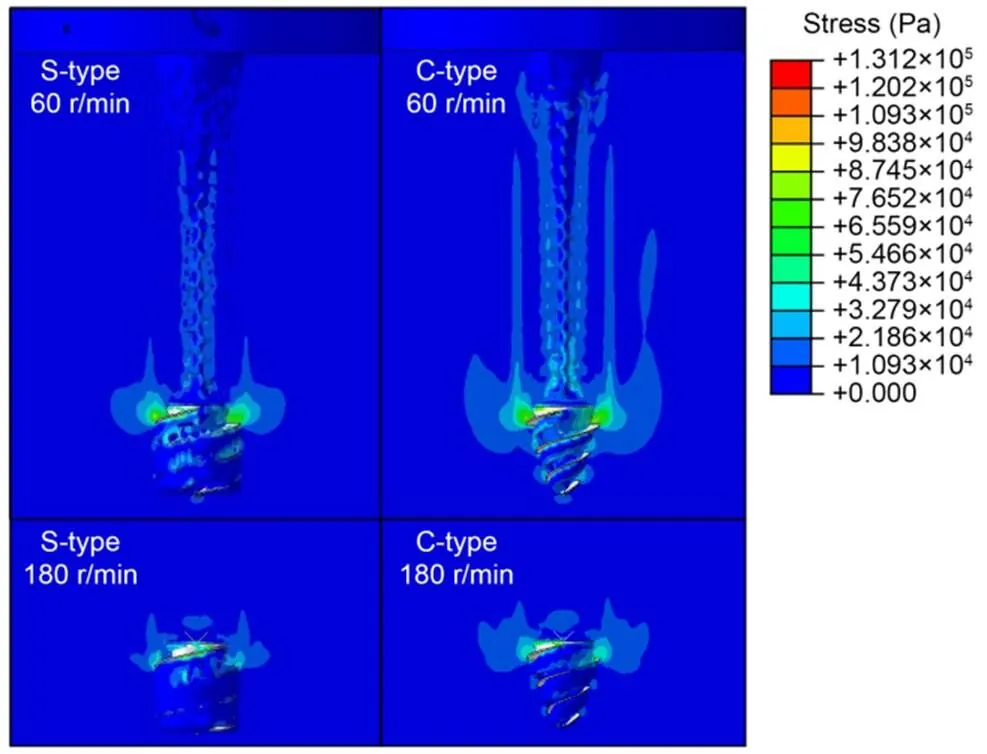
Fig. 10 Volume average stress of the soil caused by the drilling

Table 1 Parameter setting in Abaqus
By extracting the reaction force at the reference point on the drill bit, curves of the penetration force were obtained (Fig. 11). In Fig. 11, positive values indicate the direction of the upward force, which is the resistance force, and negative values indicate the direction of the downward force, which is the propulsive force. The S-type bit showed propulsive forces of 1090 to 1350 N when drilling to a depth of 96 cm, while the C-type bit showed propulsive forces of only 770 to 1100 N. Although these propulsive forces include the earth pressure at that depth, the force difference between the two drill bits is still meaningful, especially at the three lower rotation speeds, showing the advantage of the S-type bit in providing propulsive force. At a rotation speed of 180 r/min, the S-type bit also provided 250 N more than the C-type bit, and the S-type bit had a significant advantage in penetration force over the C-type bit.
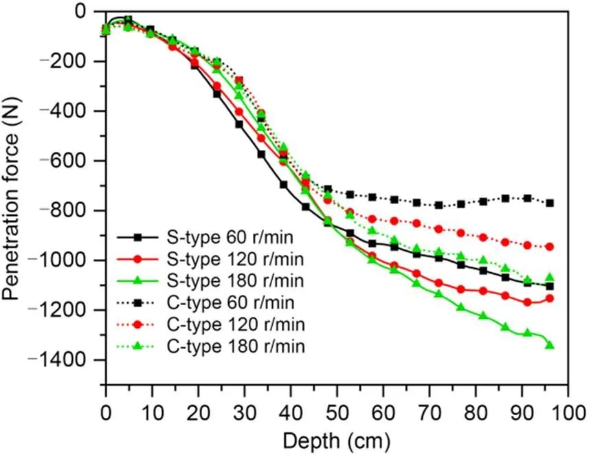
Fig. 11 Penetration forces of S-type and C-type bits in the simulated drilling process
According to the comparison of the torque curves of the two drill bits shown in Fig. 12, the torque of the S-type bit hardly increased with the increase of rotation speed: the variation of torque with depth was basically the same for the three rotation speeds, and the maximum torque was between 110 and 116 N·m. The torque of the C-type bit increased with the rotation speed, and the maximum torque ranged from 97 to 113 N·m. Typically, the torque of a drill bit is related mainly to the contact area and the soil stress. The S-type bit has larger spiral blades, so the torque should theoretically be greater than that of a C-type bit. However, the torques of the C-type bit were overall the same as those of the S-type bit. This shows that as the bit is able to provide more propulsion, the torque increases. The advantage of the S-type bit is that the torque does not increase significantly with the increase in propulsive force.
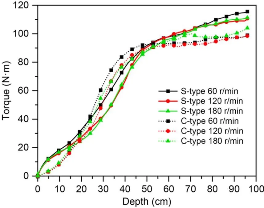
Fig. 12 Torques of S-type and C-type bits in the simulated drilling process
As the specific energy of the drilling process is related mainly to the drilling pressure, torque and the cross-sectional area of the drill bit, according to the penetration force and torque data of the simulation process, it can be calculated that the maximum specific energy of both drill bits was almost the same: about 0.4 MJ/m³ at a speed of 180 r/min (Teale, 1965; Pessier and Fear, 1992; Chen et al., 2014).
4 Comparison analysis of the drill bits based on tests
To further verify the advantages of the drilling effect of the S-type bit, a test device capable of simultaneously measuring the penetration resistance and torque of the drill bit during its drilling process was designed. The structure of the device is shown in Fig. 13. The test relies on a lead screw-slider to provide the speed and distance of the drilling process and a hydraulic motor to provide the rotation motion of the drill bit. The simulated soil in the soil bucket was prepared according to the parameters and composition of the subsea sediment stratum soil at a depth of 200 m near the coast in the South China Sea area: 65% by mass of bentonite with a particle size of about 48 μm and 35% by mass of quartz sand with a particle size of about 300 μm were added with a sufficient amount of water, mixed uniformly and solidified for three days before each experiment.
A speed of 20 mm/s, which is the closest to the motion speed of the drilling robot during peristaltic drilling motion in the seabed stratum, was chosen to simulate the down drilling speed of these two types of drill bits in the soil bucket. Rotation speeds of 60, 120, and 180 r/min were selected, and the soil depth was 70 cm. To avoid boundary property changes in the soil near the bucket wall, the drilling depth was about 55 cm. The test was carried out three times to ensure the credibility of the test results. The test procedure is shown in Fig. 14.
The penetration force curves of the S-type and C-type bit drilling process were obtained from the drilling tests (Fig. 15). In Fig. 15, the self-weight of the drill bit has been excluded, i.e., the penetration force is 0 when the drill bit is in the static state. The penetration force of both drill bits decreased with the increase of rotation speed, and the trend of the curves for the same rotation speed was similar. The penetration force of the C-type bit was about 19, 16, and 12 N, respectively, at the maximum depth, while that of the S-type bit was 32, 23, and 11 N, respectively, at the three rotation speeds. Thus, the resistance of the S-type bit was greater than that of the C-type bit at the lower rotation speeds. This is because the S-type bit's overall shape is cylindrical, while the C-type bit has a conical shape, and the cavity expansion caused by the C-type bit is smaller than that of the S-type bit. However, as the speed increases, the advantage of the S-type bit emerges, and the propulsive force brought about by the larger blade area to discharge the soil debris offsets the penetration resistance, and the penetration force of the S-type bit becomes smaller than that of the C-type bit at 180 r/min.
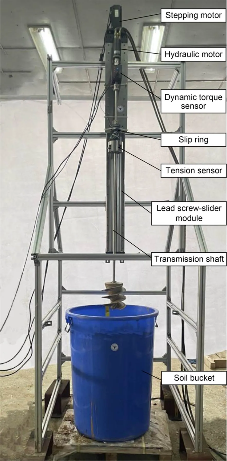
Fig. 13 Test bed of the drilling process
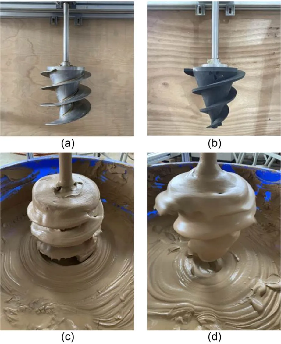
Fig. 14 Test procedure for two types of drill bits: (a) S-type bit; (b) C-type bit; (c) S-type bit after the drilling process; (d) C-type bit after the drilling process
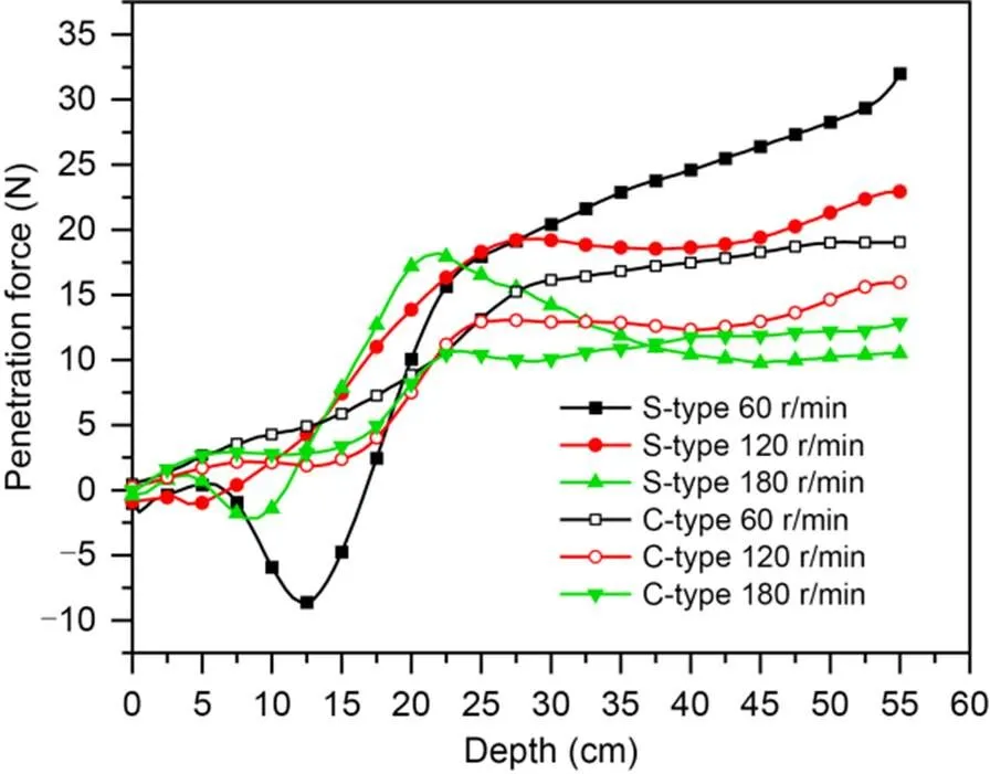
Fig. 15 Penetration forces of S-type and C-type bits in the drilling test
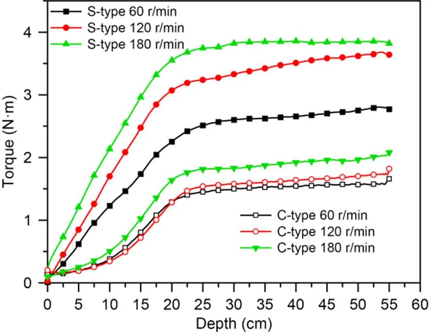
Fig. 16 Torques of S-type and C-type bits in the drilling test
The torque of the two types of drill bits also had the same changing trend (Fig. 16). The maximum torque of the C-type bit was 1.6, 1.8, and 2.1 N·m, respectively, and that of the S-type bit was 2.8, 3.6, and 3.8 N·m, respectively, at the three rotation speeds. Thus, the torque of the S-type bit was 1.75–2.00 times that of the C-type bit at the same rotation speed. The area of contact between the S-type bit and the soil was 1.84 times the contact area of the C-type bit, i.e., the torque of both drill bits was proportional to the surface area at the same rotation speed.
In the drilling tests, the torque of the S-type bit was always greater than that of the C-type bit at the same speed, resulting in a specific energy 1.8 times higher than that of the C-type bit at a rotation speed of 180 r/min.
5 Discussion
The effectiveness and advantages of the self-propelling drill bit in reducing penetration resistance were verified through simulations and tests, but there are some points that need further discussion.
5.1 Propulsive force of drill bits
The S-type bit can provide propulsive force by discharging soil debris. In the FEM simulations, the S-type bit always had better penetration force at the same rotation speed. Although the penetration force of both drill bits showed resistance in the tests, the larger cross-sectional area of the S-type bit gave it greater penetration resistance than the C-type bit at a lower speed. However, at a speed of 180 r/min, the penetration resistance of the S-type bit was lower, indicating that its structure was beneficial for propulsion at higher rotation speeds.
In the tests, the deep drilling depth required a long drive shaft, so the drive shaft from the torque sensor to the bit was 1 m. The long drive shaft limited any further increase in rotation speed, which reduced the richness of the drilling test data. In future research, the test bed needs to be improved to increase the rotation speed and obtain abundant test data for comparing rotation speed, penetration force, and torque.
5.2 Torque of drill bits
The torque of both bits in the simulations was significantly greater than that in the tests, but in the simulations the torque did not increase with the rotation speed. This may have been due to the entry of overlying water into the soil during the drilling process in the tests, causing fluidization of the soil. The soil shows rheological behavior; therefore, fluidization would reduce the viscosity as well as the shearing force of the soil, resulting in a lower penetration force and torque of the bits. In the rheological state, the rotation speed will affect the viscosity, and therefore the torque of the drill bit (Karmakar and Kushwaha, 2006; Lin et al., 2019). Comparing the simulations and tests, it can be seen that the trends of propulsive force and torque of the S-type bit were similar, and there was still a propulsive advantage. In the actual application scenario, as the drilling depth increased, the soil strength increased, and the ability of the S-type bit to discharge debris became significant as the soil showed solid behavior.
In simulations and tests, the S-type bit has a disadvantage in terms of specific energy compared to the C-type bit. However, considering the urgent need for robots to overcome the penetration resistance due to the lack of a continuous and stable drilling pressure, like in a drilling rig, more power consumption is acceptable in reducing the penetration resistance to some extent.
5.3 Environmental pressure of the drilling process
The tests in this study were conducted under atmospheric pressure conditions. The structural strength and shear modulus of the soil under real subsea strata are greater than those of in-situ sampled reconsolidated soil or prepared soil (Ren, 2021). However, the change in soil properties with depth is similar, which means that the advantages of the drill bit revealed by the simulations and existing tests are still credible. Subsequent long-term super-consolidation of the test soil by applied loads or in-situ tests is needed to obtain accurate test data.
6 Conclusions
A subsea drilling robot needs to break the soil at the front end to reduce resistance when moving in a seabed stratum. In this study, a self-propelling drill bit was designed that has the ability to convert the soil debris discharging process into propulsive force while drilling. The key parameters of the drill bit design and motion process were determined by theoretical analysis of the lead angle of soil transport. Analyses based on the FEM simulation software Abaqus were carried out to verify the reduction in penetration resistance of the designed drill bit. Finally, drilling tests were conducted in simulated subsea soil to obtain the penetration force and torque curves of the bits. We can conclude that:
1. The range of soil stress response caused by the self-propelling drill bit is smaller than that of a conventional conical bit. The cylindrical self-propelling drill bit can discharge the soil debris and reduce the range of disturbance. The range of soil stress response induced by the conical bit was more than 1.3 times that of the self-propelling bit at the speeds tested in this study.
2. The self-propelling drill bit can reduce penetration resistance by discharging. Its propulsive forces in the simulations at three rotation speeds were 1.28–1.46 times those of the conical drill bit. In the test at 180 r/min, the resistance of the self-propelling drill bit was 80% of that of the conical drill bit.
3. The propulsive force of the self-propelling drill bit increases with the rotation speed. The speed of soil debris transport increases with the rotation speed, causing a greater reaction force to the drill bit.
4. The torque of self-propelling drill bit was greater than that of the conical drill bit. The torque of the self-propelling drill bit was 1.10–1.14 times that of the conical drill bit in the simulations, rising to double when the rotation speed was 180 r/min in the test, due to soil fluidization.
Acknowledgments
This work is supported by the Hainan Provincial Joint Pro ject of Sanya Yazhou Bay Science and Technology City (No. 2021JJLH0051), the Finance Science and Technology Project of Hainan Province (No. ZDKJ202019), and the 2020 Research Program of Sanya Yazhou Bay Science and Technology City (No. SKYC-2020-01-001), China.
Author contributions
Peihao ZHANG designed the research. Xingshuang LIN, Peihao ZHANG, and Hao WANG processed the corresponding data. Peihao ZHANG and Zhenwei TIAN wrote the first draft of the manuscript. Peng ZHOU and Ziqiang REN helped to organize the manuscript. Jiawang CHEN revised and edited the final version.
Conflict of interest
Peihao ZHANG, Xingshuang LIN, Hao WANG, Jiawang CHEN, Zhenwei TIAN, Zixin WENG, Peng ZHOU, and Ziqiang REN declare that they have no conflict of interest.
Abe R, Kawamura Y, Kamijima K, et al., 2010. Performance evaluation of contra-rotating drill for DIGBOT. Proceedings of the SICE Annual Conference, p.885-888.
Becker F, Boerner S, Lichtenheldt R, et al., 2016. Enabling autonomous locomotion into sand–a mobile and modular drilling robot. Proceedings of the 47th International Symposium on Robotics, p.1-6.
Chen H, 2016. Finite Element Analysis on the Operation of Submarine Move-in-Soil Robot Based on CEL Algorithm. MS Thesis, Tianjin University, Tianjin, China (in Chinese).
Chen XY, Fan HH, Guo BY, et al., 2014. Real-time prediction and optimization of drilling performance based on a new mechanical specific energy model., 39(11):8221-8231. https://doi.org/10.1007/S13369-014-1376-0
Dai JC, Snyder F, Gillespie D, et al., 2008. Exploration for gas hydrates in the deepwater, northern Gulf of Mexico: part I. A seismic approach based on geologic model, inversion, and rock physics principles., 25(9):830-844. https://doi.org/10.1016/J.MARPETGEO.2008.02.006
Dorsch DS, Winter VAG, 2014. Design of a low energy, self contained subsea burrowing robot based on localized fluidization exhibited by Atlantic razor clams. Proceedings of the ASME International Design Engineering Technical Conferences and Computers and Information in Engineering Conference. https://doi.org/10.1115/DETC2014-34953
Isaka K, Tsumura K, Watanabe T, et al., 2019. Development of underwater drilling robot based on earthworm locomotion., 7:103127-103141. https://doi.org/10.1109/ACCESS.2019.2930994
Karmakar S, Kushwaha RL, 2006. Dynamic modeling of soil–tool interaction: an overview from a fluid flow perspective., 43(4):411-425. https://doi.org/10.1016/J.JTERRA.2005.05.001
Kim D, 2021. Large deformation finite element analyses in TBM tunnel excavation: CEL and auto-remeshing approach., 116:104081. https://doi.org/10.1016/j.tust.2021.104081
Kubota T, Nakatani I, Watanabe K, et al., 2005. Study on mole-typed deep driller robot for subsurface exploration. Proceedings of the IEEE International Conference on Robotics and Automation, p.1297-1302. https://doi.org/10.1109/ROBOT.2005.1570294
Lebedev SV, 2011. Torque and axial force at the surface of a blade in a conical helical anchor., 31(5):424-427. https://doi.org/10.3103/S1068798X11050133
León R, Llorente M, Giménez-Moreno CJ, 2021. Marine gas hydrate geohazard assessment on the European continental margins. The impact of critical knowledge gaps., 11(6):2865. https://doi.org/10.3390/APP11062865
Lin Y, Zhu H, Wang W, et al., 2019. Rheological behavior for laponite and bentonite suspensions in shear flow., 9(12):125233. https://doi.org/10.1063/1.5129211
Livneh B, El Naggar M, 2008. Axial testing and numerical modeling of square shaft helical piles under compressive and tensile loading., 45(8):1142-1155. https://doi.org/10.1139/T08-044
McConnell DR, Zhang ZJ, Boswell R, 2012. Review of progress in evaluating gas hydrate drilling hazards., 34(1):209-223. https://doi.org/10.1016/J.MARPETGEO.2012.02.010
Nagaoka K, Kubota T, Otsuki M, et al., 2008. Experimental study on autonomous burrowing screw robot for subsurface exploration on the Moon. 2008 IEEE/RSJ International Conference on Intelligent Robots and Systems, p.4104-4109. https://doi.org/10.1109/IROS.2008.4650693
Nagaoka K, Kubota T, Otsuki M, et al., 2009. Robotic screw explorer for lunar subsurface investigation: dynamics modelling and experimental validation. Proceedings of the International Conference on Advanced Robotics, p.1-6.
Pessier RC, Fear MJ, 1992. Quantifying common drilling problems with mechanical specific energy and a bit-specific coefficient of sliding friction. Proceedings of the SPE Annual Technical Conference and Exhibition. https://doi.org/10.2118/24584-MS
Qiu G, Henke S, Grabe J, 2009. Applications of coupled Eulerian-Lagrangian method to geotechnical problems with large deformations. 2009 SIMULIA Customer Conference, p.420-435.
Qiu G, Henke S, Grabe J, 2011. Application of a coupled Eulerian–Lagrangian approach on geomechanical problems involving large deformations., 38(1):30-39. https://doi.org/10.1016/J.COMPGEO.2010.09.002
Rafeek S, Gorevan SP, Bartlett PW, et al., 2001. The inchworm deep drilling system for kilometer scale subsurface exploration of Europa (IDDS). Proceedings of the Forum on Innovative Approaches to Outer Planetary Exploration 2001-2020, p.68.
Ren YB, 2021. Study on the Mechanism of Cyclic Softening and Thixotropy Hardening of Strong Structural Deep-Sea Soft Clay. PhD Thesis, Dalian University of Technology, Dalian, China (in Chinese). https://doi.org/10.26991/d.cnki.gdllu.2021.003838
Soloviev V, Ginsburg GD, 1994. Formation of submarine gas hydrates., 41:86-94. https://doi.org/10.37570/bgsd-1995-41-09
Tadami N, Nagai M, Nakatake T, et al., 2017. Curved excavation by a sub-seafloor excavation robot. Proceedings of the IEEE/RSJ International Conference on Intelligent Robots and Systems, p.4950-4956. https://doi.org/10.1109/IROS.2017.8206376
Tang D, Zhang W, Jiang S, et al., 2015. Development of an Inchworm Boring Robot (IBR) for planetary subsurface exploration.015 IEEE International Conference on Robotics and Biomimetics (ROBIO), p.2109-2114. https://doi.org/10.1109/ROBIO.2015.7419085
Teale R, 1965. The concept of specific energy in rock drilling., 2(1):57-73. https://doi.org/10.1016/0148-9062(65)90022-7
Tian Z, Chen J, Zhang P, et al., 2021. Design of a drilling unit for deep-sea stratum drilling robot., 861:072031. https://doi.org/10.1088/1755-1315/861/7/072031
Wei C, Wang HL, Liu TX, 2013. Mechanical model of hollow-external-screw drill rod for lunar soil particle vertical conveying. Proceedings of the 10th IEEE International Conference on Control and Automation, p.1240-1245. https://doi.org/10.1109/ICCA.2013.6565063
Winter AG, Deits RLH, Dorsch DS, et al., 2014. Razor clam to RoboClam: burrowing drag reduction mechanisms and their robotic adaptation., 9(3):036009. https://doi.org/10.1088/1748-3182/9/3/036009
Zhang J, Kushwaha RL, 1995. A modified model to predict soil cutting resistance., 34(3):157-168. https://doi.org/10.1016/0167-1987(95)00466-6
Zhang TQ, Taylor RN, Zheng G, et al., 2018. Modelling ground movements near a pressurised tunnel heading in drained granular soil., 104:152-166. https://doi.org/10.1016/j.compgeo.2018.08.015
Zhang WW, Jiang SY, Tang DW, et al., 2017. Drilling load model of an inchworm boring robot for lunar subsurface exploration., 2017:1282791. https://doi.org/10.1155/2017/1282791
Zheng XY, Zhao WM, Su JZ, 2013. Unconventional excavation study of the spiral drill pipe., 26(2):61-63 (in Chinese). https://doi.org/10.3969/j.issn.1007-4414.2013.02.022
Zhu CQ, Zhang MS, Liu XL, et al., 2017. Gas hydrates: production, geohazards and monitoring., 32(3):51-56 (in Chinese). https://doi.org/10.3969/j.issn.1000-811X.2017.03.010
应用于海底地层钻探机器人的自推进钻头设计及自推进效果对比分析
张培豪1,2,林型双1,2,王豪1,2,陈家旺1,2,3,田祯玮1,翁子欣1,任自强1,2,周朋1
1浙江大学,海洋学院,中国舟山,316021;2浙江大学,海南浙江大学研究院,中国三亚,572025;3海洋感知技术与装备教育部工程研究中心,中国舟山,316000
海底地层钻探机器人作为一种新型的海底地层地质调查手段具有广阔的应用前景。本文旨在分析并设计一种新型的自推进式螺旋钻头,以减小机器人在地层中运动时的前端阻力。1. 通过理论建模分析,推导出新型自推进螺旋钻头的螺旋升角与土壤钻屑排出运动的关系;2. 建立仿真模型,成功模拟钻头在海底土壤中的钻进过程,并通过其贯入力和扭矩分析其自推进效果;3. 设计试验装置,成功模拟钻头在土壤中的钻进过程,并通过其贯入力和扭矩进一步验证其自推进效果。1. 通过理论推导,构建螺旋叶片升角与土壤钻屑排出运动之间的关系,得到具有设计优势的新型自推进钻头。2. 通过Abaqus有限元仿真软件,采用耦合欧拉-拉格朗日方法进行钻头钻进过程的仿真分析,可视化观察钻头钻进过程对周围土壤的扰动范围(图9);对比自推进钻头与传统锥形钻头在相同转速下轴向贯入力上的差别,确定其自推进效果的优势(图10)。3. 通过试验,进一步验证所设计的自推进钻头在配制的模拟海底土壤中的减阻钻进效果(图14)。1. 自推进钻头钻进过程对周围土壤的影响范围小于传统锥形钻头;2. 自推进钻头能够靠排出土屑提供推进力,因而有着更小的钻进阻力;3. 自推进钻头的轴向推进力随着转速的增加而不断增大,所以较高转速有着更好的钻进减阻优势;4. 自推进钻头的扭矩高于传统锥形钻头。
海底地层调查;钻探机器人;自推进钻头;钻进阻力
July 16, 2022;
https://doi.org/10.1631/jzus.A2200351
https://doi.org/10.1631/jzus.A2200351
Jiawang CHEN, https://orcid.org/0000-0002-6351-0062
Revision accepted Nov. 4, 2022;
Crosschecked Feb. 1, 2023;
Online first Mar. 2, 2023
© Zhejiang University Press 2023
 Journal of Zhejiang University-Science A(Applied Physics & Engineering)2023年10期
- Journal of Zhejiang University-Science A(Applied Physics & Engineering)的其它文章
- Using pipette tips to readily generate spheroids comprising single or multiple cell types
- Microfluidic fuel cells integrating slanted groove micro-mixers to terminate growth of depletion boundary layer thickness
- Experimental investigation of the thermal insulation performance of Ce/Si/Ti oxide heat-reflective coating
- Geo-environmental properties and microstructural characteristics of sustainable limestone calcined clay cement (LC3) binder treated Zn-contaminated soils
- Effect of CO2-mixing dose and prolonged mixing time on fresh and hardened properties of cement pastes
- Micro-Newton scale variable thrust control technique and its noise problem for drag-free satellite platforms: a review
