
Microfluidic fuel cells integrating slanted groove micro-mixers to terminate growth of depletion boundary layer thickness
2023-10-24 02:14:40JinchiSUNXiongweiTIANZhangqingLIUJieSUNMenglianZHENG
Jinchi SUN, Xiongwei TIAN, Zhangqing LIU, Jie SUN, Menglian ZHENG,3
Research Article
Microfluidic fuel cells integrating slanted groove micro-mixers to terminate growth of depletion boundary layer thickness

1Institute of Thermal Science and Power Systems, College of Energy Engineering, Zhejiang University, Hangzhou 310027, China2Institute of Energy and Environment Engineering, NingboTech University, Ningbo 315100, China3State Key Laboratory of Clean Energy Utilization, Hangzhou 310027, China
Because of potential high energy densities, microfluidic fuel cells can serve as micro-scale power sources. Because microfluidic fuel cells typically operate in the co-laminar flow regime to enable a membrane-less design, they generally suffer from severe mass transfer limitations with respect to diffusion transport. To address this issue, a novel channel design that integrates slanted groove micro-mixers on the side walls of the channel is proposed. Numerical modeling on the design of groove micro-mixers and grooveless design demonstrates a mass transfer enhancement that has a 115% higher limiting current density and well-controlled convective mixing between the oxidant and the fuel streams with the use of slanted groove micro-mixers. Moreover, the growth of the thickness of the depletion boundary layer is found to be terminated within approximately 2 mm from the channel entrance, which is distinct from the constantly growing pattern in the grooveless design. In addition, a simplified mass transfer model capable of modeling the mass transfer prFocess with the presence of the transverse secondary flow is developed. Further, a dimensionless correlation is derived to analyze the effects of the design parameters on the limiting current density. The present theoretical study paves the way towards an optimal design of a microfluidic fuel cell integrating groove micro-mixers.
Microfluidic; Fuel cell; Membraneless; Slanted groove micro-mixer; Mass transfer; Depletion boundary layer
1 Introduction
Over the past few decades, studies on micro-scale power sources with high power densities and extended charging/discharging durations have been motivated by social demands for portable devices, such as cell phones, laptops, and portable instruments for diagnostics and field-trip analysis (Kundu et al., 2007; Moreno-Zuria et al., 2017; Gurrola et al., 2021). While the development of traditional batteries is thought to be unlikely to meet the growing power requirement of portable devices, micro fuel cells have become a pro mising substitute power source owing to their high energy densities and ease of recharge by refilling fuels (Dyer, 2002; Modestino et al., 2016).
The miniaturization of conventional fuel cells by an approach based on micro-electromechanical systems has led to several types of membrane-based micro fuel cells, such as micro proton exchange membrane fuel cells and micro direct methanol fuel cells (Nguyen and Chan, 2006). More recent studies have demonstrated that the laminarity of the flow at the micro scale can be exploited to develop membrane-less micro fuel cells, which are also called microfluidic fuel cell (Ferrigno et al., 2002; Cohen et al., 2005a, 2005b). In a typical microfluidic fuel cell, the electrolytes (the oxidant stream and the fuel stream) flow side-by-side down a single channel and mixing between the electrolytes occurs by diffusion alone (Kjeang et al., 2009). The exclusion of the proton exchange membrane enables the elimination of the membrane fouling or damage issue (Ferrigno et al., 2002), better water management (Choban et al., 2005b), reduced system cost (Tsuchiya and Kobayashi, 2004), and simplified fabrication of the micro fuel cell (Ferrigno et al., 2002).
Since the invention of microfluidic fuel cells by Ferrigno et al. (2002), various types of fuels and oxidants (Ferrigno et al., 2002; Choban et al., 2004, 2005a, 2005b; Hasegawa et al., 2005; Lee et al., 2007; Brushett et al., 2009), supporting electrolytes (Choban et al., 2005a, 2005b; Jayashree et al., 2006; Brushett et al., 2009), and electrode materials (Kjeang et al., 2007c; Lee and Kjeang, 2013) have been investigated to improve their performance. The power density of microfluidic fuel cells has been significantly improved to a figure that is comparable to that of micro direct methanol fuel cells (Shaegh et al., 2011). However, the high power densities reported in the literature have mostly been achieved at elevated flow rates at the cost of reduced fuel utilization efficiency (Jayashree et al., 2010). At relatively low flow rates, the power densities decrease drastically owing to the severe mass transfer limitations with respect to the diffusion transport (Ferrigno et al., 2002; Choban et al., 2004; Bazylak et al., 2005; Kjeang et al., 2007a; Ahmed et al., 2008; Shaegh et al., 2012). Therefore, in recent studies on microfluidic fuel cells, effective approaches for mass transfer enhancement have been stressed with the aim of achieving high power densities without significantly elevated flow rates (Nasharudin et al., 2014).
The air-breathing microfluidic fuel cell, in which a gas diffusion electrode was used as the cathode, was proposed by Jayashree et al. (2005) to address the mass transfer limitation at the cathode (Choban et al., 2005a; Chang et al., 2006) for microfluidic fuel cells using formic acid or methanol as the fuel and dissolved oxygen as the oxidant. With the oxygen delivered directly from the ambient air, four orders of magnitude higher diffusivity and more than doubled concentration of the oxygen were achieved, resulting in the peak power density being increased by more than four-fold (Jayashree et al., 2005). Later measurements confirmed that this air-breathing microfluidic fuel cell was no longer limited in mass transfer at the cathode (Jayashree et al., 2010). Further, microfluidic fuel cells using flow-through porous electrodes were pioneered by Kjeang et al. (2008) in which the fuel and oxidant streams were forced to flow through porous electrodes before merging and flowing side-by-side, thus enhancing the mass transfer of the reactants to the electrodes. Experiments with all-vanadium redox couples showed that the peak power density and fuel utilization nearly tripled and doubled, respectively, compared to the microfluidic fuel cell that used planar electrodes in the Reynolds number range of=2–20. The performance of this design, however, cannot be sustained at high current densities owing to increases in the ohmic losses (Kjeang et al., 2008; Lee and Kjeang, 2013). Shaegh et al. (2012) demonstrated that such a flow-through porous electrode can also be applied to air-breathing microfluidic fuel cells as the anode for mass transfer enhancement, though at the expense of increased pressure drops.
Alternatively, mass transfer enhancement in microfluidic fuel cells can be achieved by integrating groove micro-mixers. For example, the integration of slanted groove micro-mixers (SGMs) in a microfluidic fuel cell was pioneered by Yoon et al. (2006). Their experimental study of the microfluidic fuel cell with symmetrical herringbone ridges patterned along the bottom wall of the channel demonstrated a 10%–40% higher fuel utilization compared to a microfluidic fuel cell without ridges. The mass transfer enchantment was attributed to the continuous replacement of the depletion boundary layer with fresh solution from the bulk electrolyte, which was facilitated by the transverse secondary flow induced by the ridges (Yoon et al., 2006). Although beneficial to the mass transfer process, the presence of the transverse secondary flow can lead to convective mixing between the electrolytes (i.e., the oxidant and the fuel streams) and thus cause problems with operations owing to fuel crossover (when the mixing region overlaps with the electrode and a parasitic current is generated) (Xuan et al., 2011). To address the fuel crossover issue, optimized symmetrical herringbone ridges with an additional ridge along the centerline were proposed by Marschewski et al. (2015). By adding an extra ridge, convective mixing between the electrolytes was under control up to≈325, and the limiting current density was more than doubled compared to the microfluidic fuel cell without ridges in the range of=155–470 (Marschewski et al., 2015). Integration of staggered herringbone mixers (SHMs) in microfluidic fuel cells has also been studied. Xuan et al. (2011) theoretically studied a microfluidic fuel cell with staggered herringbone ridges patterned along the bottom wall of the channel and demonstrated a mass transfer enhancement compared to that for microfluidic fuel cells without ridges. A counter-flow configuration was used to avoid convective mixing between the electrolytes but was at the expense of increased ohmic losses.
In addition to topographical patterning of the channel wall, the integration of groove micro-mixers in microfluidic fuel cells can also be implemented by using groove electrodes. For example, Ha and Ahn (2014) reported that a 36.56% higher peak power density was achieved by using electrodes incorporating 0.1-μm-deep slanted grooves (Lee and Ahn, 2015). Only minor convective mixing occurred due to the weakness of the transverse secondary flow triggered by the grooves. The microfluidic fuel cell with 50-μm-deep grooves etched on the electrodes in the staggered-herringbone pattern was studied by da Mota et al. (2012). More than doubled peak power density and more than tripled limiting current density were achieved, with the electrolytes being separated by a non-selective porous plate to suppress convective mixing between the electrolytes.
To summarize, significant improvements in fuel utilization, limiting current density, and peak power density have been achieved by integrating groove micro-mixers in microfluidic fuel cells. However, few insights into the mass transfer process in microfluidic fuel cells that integrate groove micro-mixers have been gained even though the transverse secondary flow triggered by the groove micro-mixers has significant effects on the mass transfer process (Kirtland et al., 2009).
In the present study, a novel design of microfluidic fuel cells that integrates SGMs on the side walls of the channel is proposed and studied. By using a numerical model, the performance of the proposed microfluidic fuel cells is investigated in terms of the limiting current density and convective mixing between the electrolytes. In addition, the developing pattern of the depletion boundary layer along the channel is studied via a simplified mass transfer model approach to facilitate a deeper understanding of the mass transfer process of the reactants from the electrolyte to the electrode with the presence of the transverse secondary flow. Further, the effects of design parameters on the limiting current density are analyzed systematically using a dimensionless correlation derived from the simplified mass transfer model to achieve enhanced mass transfer.
2 Methods
2.1 Geometries of microfluidic fuel cells
As shown in Figs. 1a and 1b, in the microfluidic fuel cells proposed in the present study, SGMs are integrated on the two opposing side walls of the channel symmetrically with respect to the interface between the electrolytes. A helical flow pattern is expected to be induced in each electrolyte stream by the grooves when the electrolytes flow through the channel (Stroock et al., 2002). Two positions of the electrodes, i.e., on the top wall and on the bottom wall, are considered and these two designs are labeled as N1 and N2, respectively. The geometric parameters of the channel are determined, based on our preliminary results, to illustrate the combined effects of the grooves on mass transfer enhancement and the mixing between the electrolytes. Specifically, the aspect ratio of the cross-section of the channel, i.e.,/,is set as 1.5, and the width of the electrode (e) is set as half of the height of the channel (), where=200 μm. Referring to the guidelines for optimizing the helical flow in groove micro-mixers (Lynn and Dandy, 2007; Forbes and Kralj, 2012), the geometric parameters of the grooves are set asg/=0.2,g/g=2.5,g/=0.8, and=45°, wheregandgdenote the depth and the width of grooves, respectively,gdenotes the spacing between the centerlines of two neighboring grooves, anddenotes the tilt angle of grooves. The numbers of grooves are set to be 5, 10, 20, 40, and 80, with corresponding lengths of the electrode ofe/=5, 9, 17, 33, and 65, respectively, to explore the effects of the length of the electrode. In addition, as shown in Fig. 1c, a grooveless microfluidic fuel cell labeled N3 is also studied for comparison; it has the same dimensions (,,e, ande) as the N1 and N2 designs.
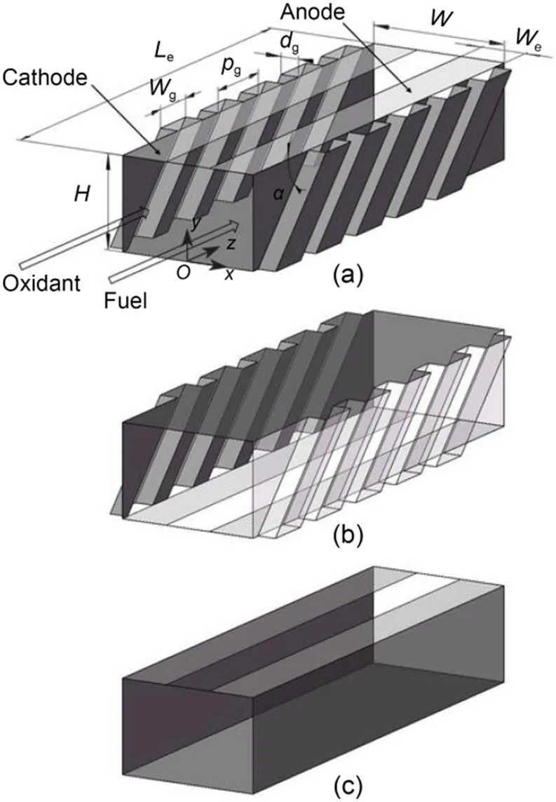
Fig. 1 Illustration of the geometries of the three microfluidic fuel cell designs of microfluidic fuel cells that integrate SGMs: (a) electrodes on the top wall, labeled as N1; (b) electrodes on the bottom wall, labeled as N2; (c) grooveless microfluidic fuel cell, labeled as N3
2.2 Numerical model
In the present study, iron (II) sulfate (10 mol/m3) in 1000-mol/m3sulfuric acid, and anthraquinone (5 mol/m3) in 1000-mol/m3sulfuric acid are used as the fuel and oxidant, respectively. The reactions at the anode and cathode are shown in Eqs. (1) and (2), respectively:


where0is the standard potential of the reaction, and AQ2S is the anthraquinone-2-sulphonate. To highlight the mass transfer enhancement by integrating SGMs, the operation of the microfluidic fuel cells in the mass transfer limited regime is modeled. Recognizing that the diffusion coefficient of the reactant in the fuel stream (Fe2+, 1.0×10⁻¹⁰m2/s (Modestino et al., 2016)) is smaller than that of the reactant in the oxidant stream (AQ2S, 2.7×10⁻¹⁰m2/s (Modestino et al., 2016)), it is assumed that the limiting current density of the fuel cell is determined by mass transfer of reactant in the fuel stream, i.e., Fe2+, which is modeled as follows.
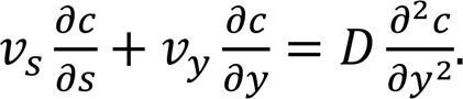
First, the flow in the channel is modeled by the steady-state continuity equation and Navier-Stokes equation for incompressible flow with constant physical properties as:
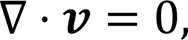
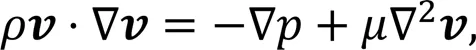
whereis the velocity vector,is the density of the electrolytes,is the dynamic viscosity of the electrolytes, andis the pressure.
A Poiseuille flow with a specified average velocityis imposed at the entrance of the channel, null velocity vector boundary conditions are used at the channel walls and the electrodes, and a zero gauge pressure condition is set at the exit of the channel.
A density of 1000-mol/m3sulfuric acid (=1059.5 kg/m3(Stroock et al., 2002)) is applied for both the fuel and oxidant streams because the concentration of the reactants is low. The dynamic viscosity of the electrolytes is set as the typical value for aqueous solutions at room temperature (=1.0×10⁻³m/s2).
The concentration distribution of Fe2+is then obtained using the steady-state convective diffusion equation:
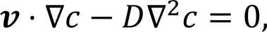
whereis the molar concentration of Fe2+, and(1×10⁻¹⁰m2/s (Marschewski et al., 2015)) is the diffusion coefficient of Fe2+.
In the mass transfer limited regime, an instantaneous reaction of Fe2+occurs at the anode (i.e., the concentration of Fe2+at the anode surfaces=0), and it is assumed that no reaction of Fe2+occurs at the cathode and channel walls. Concentration of Fe2+is set to0(10 mol/m3) at the inlet of the fuel stream and zero at the inlet of the oxidant stream.
With the concentration distribution of the reactant, the limiting current density can then be calculated:
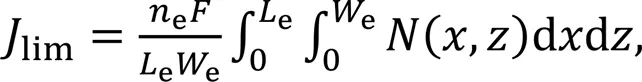
whereeis the number of transferred electrons,is the Faraday constant (equal to 96485 C/mol), and(,)=(∂/∂)sis the local flux of the reactant to the electrode calculated through Fick's law. Note that the subscript s is the short for the electrode surface.
The numerical calculation of the above equations is performed with the commercial computational fluid dynamics software ANSYS®Fluent 16.0, and structured meshes with an average size of 6 μm are generated in the software ANSYS®ICEM CFD 16.0. The meshes are further refined to an average size smaller than 1 μm near the anode to capture the concentration gradients there.
2.3 Simplified mass transfer model
To facilitate a deeper understanding of the mass transfer process in microfluidic fuel cells that integrate SGMs, a simplified mass transfer model is developed in the present study. The focus is placed on the mass transfer process within the depletion boundary layer of the fuel stream; the mass transfer processes in the bulk of the fuel and oxidant streams are out of the scope of this simplified model.
2.3.1Assumptions
(1) The microfluidic fuel cell is mass transfer limited at the anode.
(2) The thickness of the depletion boundary layer is much smaller than the height of the channel (Nguyen and Chan, 2006).
(3) The impacts of mixing between the electrolytes are neglected.
(4) The effects of the depleted electrolytes going back to the electrode owing to the helical flow induced by the SGMs (Kirtland et al., 2006) are regarded as negligible.
(5) The velocity component parallel to the electrode can be approximated by the first term in Taylor's expansions of the distance from the electrode (i.e., the assumption of shear flow) (Newman, 1968).
(6) The diffusion transport parallel to the electrode due to minor concentration gradients is regarded as negligible.
2.3.2Mathematical formulation
To make the problem explicitly solvable, the mass transfer domain is reduced to a series of 2D stream surfaces, which are vertical to the electrode under the assumption of shear flow. Thus, the mass transfer between each adjacent pair of the stream surfaces is considered to be negligible under Assumption 6. Consequently, the mass transfer process of the reactant from the electrolyte bulk to the electrode is modeled in individual stream surfaces.
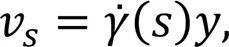
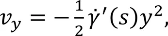
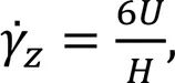
According to the shear rate assumption and the steady-state continuity equation for incompressible flow, the velocity component along the-axis (as defined in Fig. 2a),v, and the component along the-axis,v, are formulated as follows:
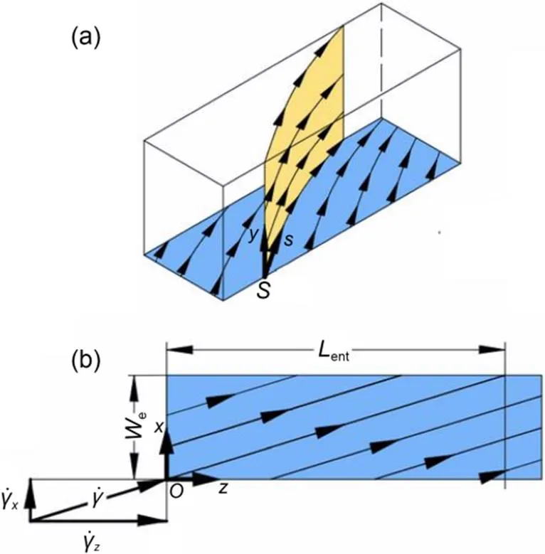
Fig. 2 Illustration of the coordinate systems used for the simplified mass transfer model: (a) semi-infinite region above the rectangular electrode surface (marked in blue), with the 2D coordinate system established in an arbitrary stream surface (marked in yellow) (curves with arrows illustrate the flow directions of the shear flow); (b) the special case where the velocity shear rate is constant over the electrode. The relation between the velocity shear rate along the s-axis and those along the x-axis and z-axis is shown. A 3D orthogonal coordinate system is established accordingly, with y-axis (not displayed) vertical to the electrode. Lent is the entrance length. References to color refer to the online version of this figure
With the diffusion transport along the-axis neglected under Assumption 6, the convective diffusion equation to be solved is:
The boundary conditions are given by:
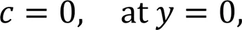
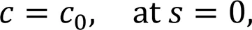

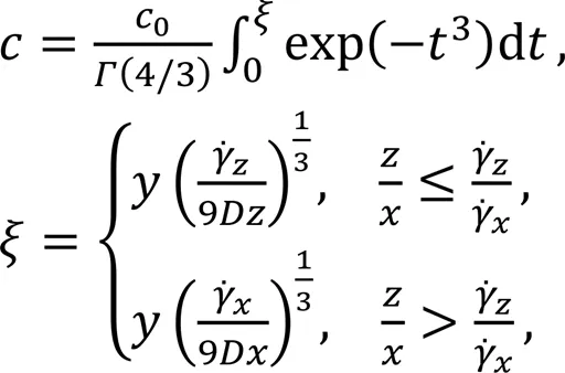
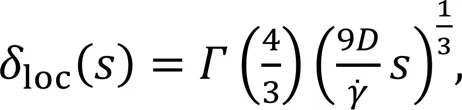
By solving the above equations, the concentration distribution of the reactant in the fuel stream (i.e., Fe2+) is expressed as:
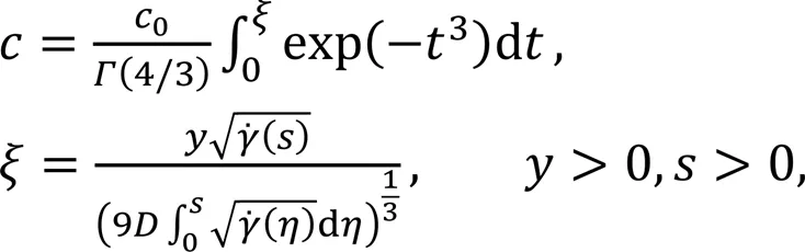
where(4/3)=0.89298,denotes an intermediate variable,is the integral variable between 0 and,is the specific spatial coordinate, andis the integral variable between 0 and.
Note that Eq. (13) is derived for an arbitrary stream surface and can be applied to the mass transfer process in a 3D domain.
2.3.3Dimensionless correlation of limiting current density
Assuming that the velocity shear rate is constant over the electrode, Eq. (13) is rewritten in the 3D orthogonal coordinate system as shown in Fig. 2b:
The local flux of the reactant to the electrode can thus be obtained by using(,)=(∂/∂)=0. To express the local rate of the mass transfer to the electrode in a dimensionless form, the local Sherwood number is defined as:
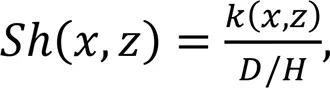
where(,) is the local mass transfer coefficient, which is defined as:
wheresis set as 0 considering an instantaneous reaction at the anode.
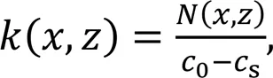
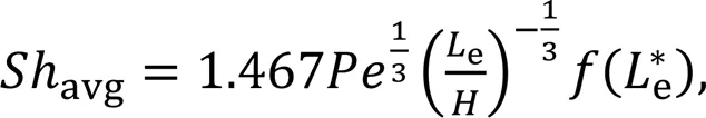
The average Sherwood number is then defined as:

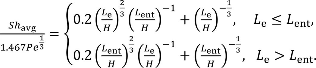
By combining Eqs. (14)–(17), the expression of the average Sherwood number can be derived as:
whereis a dimensionless function defined as:
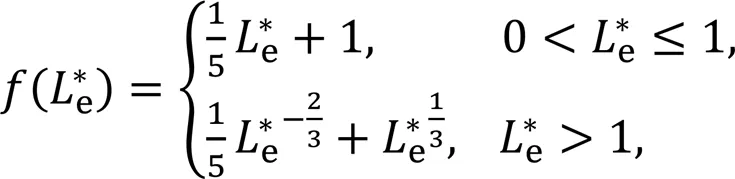
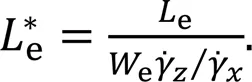
By combining Eqs. (15)–(17) and the definition of the limiting current density given by Eq. (6), the relation between the limiting current density and the average Sherwood number is given by:
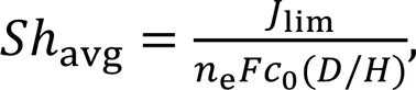
wherelimdenotes the limiting current density.
The dimensionless correlation of the limiting current density for the special case of the velocity shear rate being constant over the electrode is thus given by the expression of the average Sherwood number, i.e., Eq. (18).

wheredenotes the average velocity of the electrolyte.

The dimensionless correlation of the limiting current density for microfluidic fuel cells that integrate SGMs is then given by:
3 Results and discussion
3.1 Model validation
3.1.1Numerical model
The numerical modeling results of the limiting current density of microfluidic fuel cells at varying Reynolds number are compared against the experimental results in the previous study (Marschewski et al., 2017) to validate the credibility of the present numerical model, which is shown in Fig. 3. Results of a microfluidic fuel cell integrating SGMs on the bottom wall of the channel and a grooveless microfluidic fuel cell are presented. In general, the numerical model reproduces the scaling behavior at varying Reynolds numbers and the increase in the limiting current densities by integrating SGMs in the microfluidic fuel cell; however, it leads to lower limiting current density values than the experimental studies. While several factors neglected in the model may be responsible for the mismatch, it is suggested that the inaccuracy of parameters adopted in the model may be the dominant factor. For example, the diffusion coefficient adopted in the model (1×10⁻¹⁰m2/s for Fe2+(Marschewski et al., 2017)) may be lower than its actual value, leading to lower limiting current densities compared to the experimentally measured values. Further, in the experiments, mass transfer near the leading edge of the electrode may be enhanced by the transverse flow generated in the Y-shaped channel entrance, while this effect is neglected in the model by imposing a fully developed Poiseuille flow at the channel entrance.
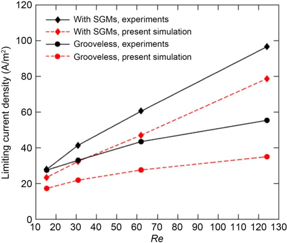
Fig. 3 Limiting current densities of microfluidic fuel cells at varying Reynolds numbers. The simulative results of the microfluidic fuel cells with and without SGMs are compared to the experimental results from Marschewski et al. (2017)
A well-established formula for grooveless microfluidic fuel cells can be used to indirectly evaluate the diffusion coefficient based on the experimentally measured limiting current densities (Stroock et al., 2002):
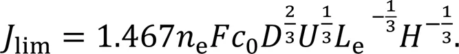
The above calculation for the diffusion coefficient yields the average value=1.9×10⁻¹⁰m2/s, which is sufficient to account for the mismatch shown in Fig. 3. Nevertheless, it should be noted that the following results have been presented in a dimensionless form and the inaccuracies and uncertainties in the parameters thus cause negligible effects on the validation of the conclusions here. Furthermore, these novel channel designs are regarded as general strategies for enhancing mass transfer of the microfluidic fuel cells, and the validation of the effectiveness of the proposed designs is not affected by inaccuracy and uncertainty in the diffusion coefficient.
3.1.2Simplified mass transfer model
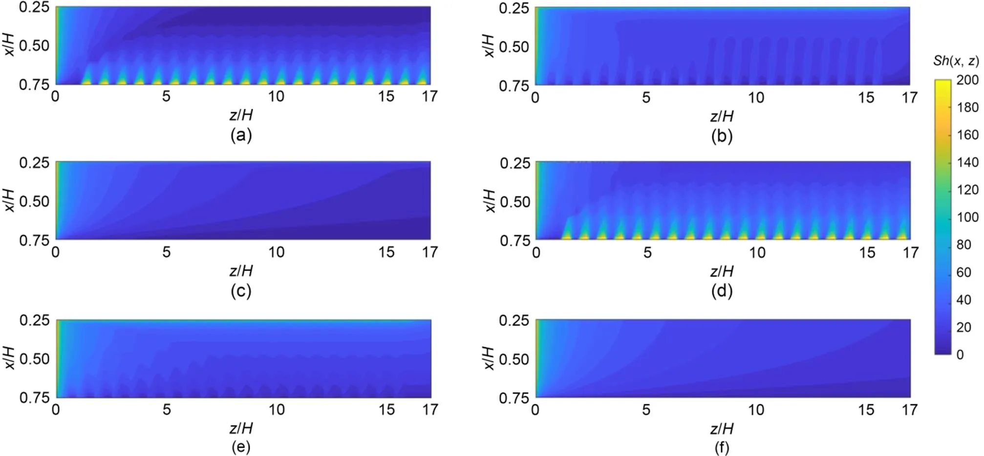
To validate the credibility of the developed simplified mass transfer model for investigating the mass transfer process within the depletion boundary layer, the predictions of local Sherwood number distributions in the proposed microfluidic fuel cells that integrate SGMs (N1 and N2 designs) are compared with the corresponding numerical results. The numerical modeling results of the velocity shear rate at the anode are used as the inputs of the simplified mass transfer model (Eq. (13)). In addition, the grooveless microfluidic fuel cell (N3 design) is also included, for which the theoretical values of the velocity shear rate of the Poiseuille flow in the rectangular channel (Kirtland et al., 2006) are used. As shown in Fig. 4, the simplified mass transfer model can capture the qualitative features of local Sherwood number distributions in the N1, N2, and N3 designs.
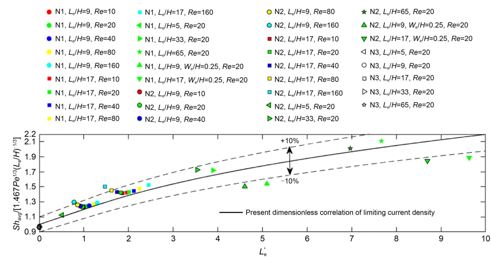
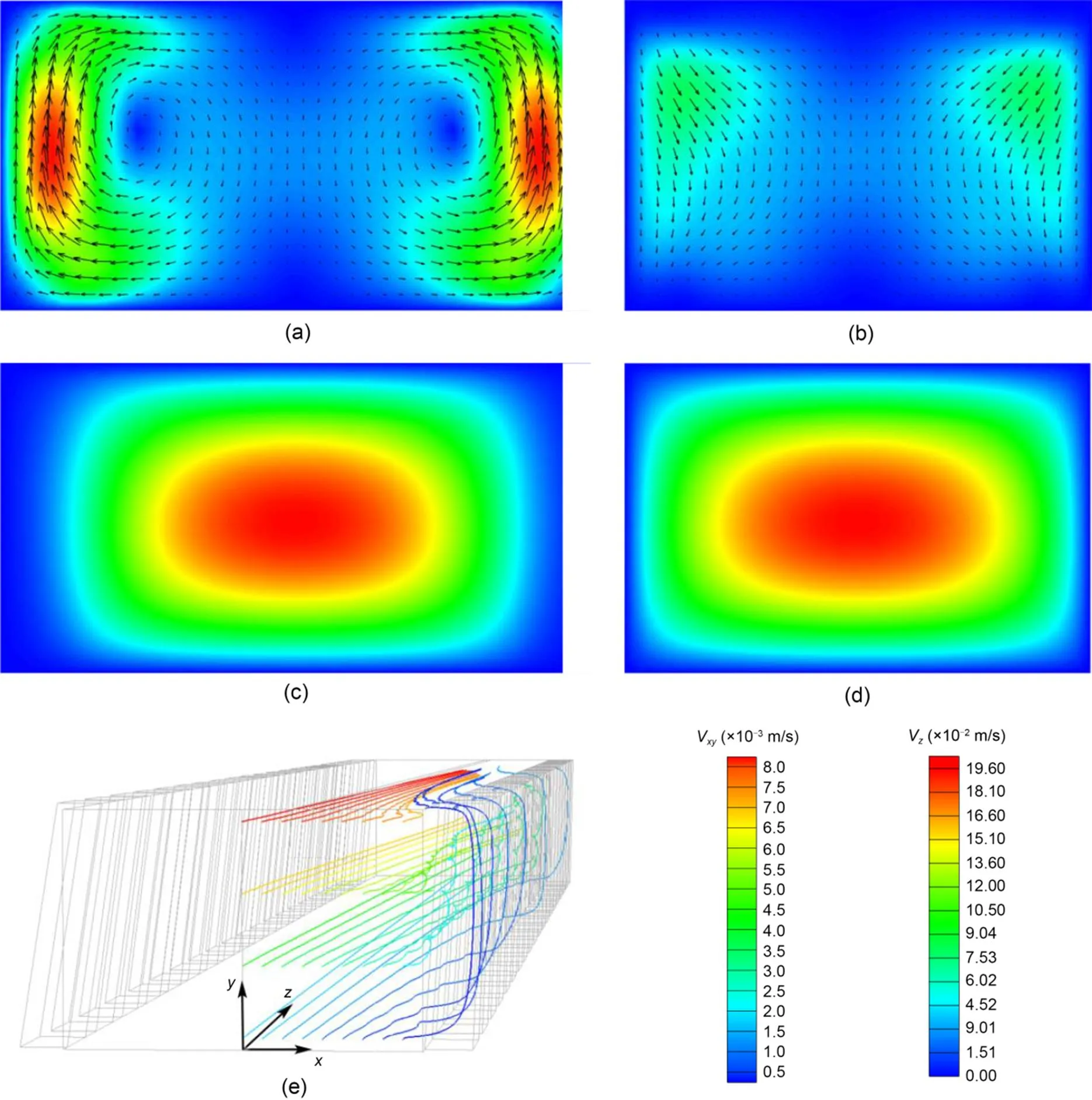
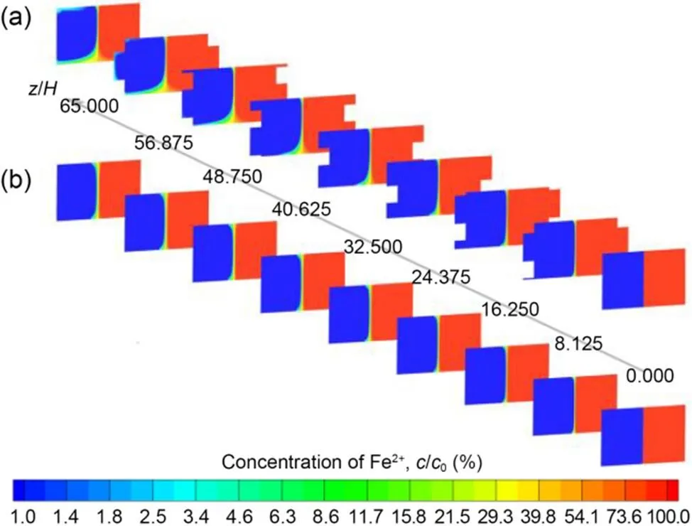
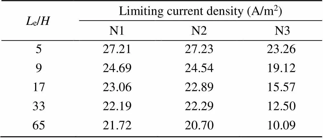
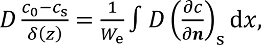
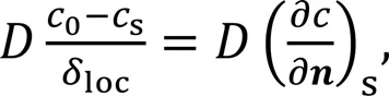
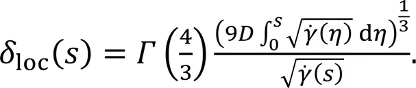
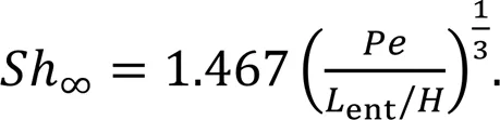
The dimensionless correlations of the limiting current density (Eq. (24)) obtained via the simplified mass transfer model are further validated by comparing the predictions of the limiting current density to those obtained using the numerical model for a variety of cases covering the range of=10–160 with 5 In the laminar flow regime, the pressure driven flow through the rectangular channel is a uniaxial Poiseuille flow. When slanted grooves are incorporated in the channel (Fig. 1), the transverse secondary flow will be generated because the fluids near the grooves are inclined in the direction along the grooves owing to the smaller flow resistance (Kjeang et al., 2007b, 2007c), which is observed in the numerical modelling results of the proposed microfluidic fuel cells that integrate SGMs. The flow pattern is shown in Fig. 6 and is the same for the N1 and N2 designs because they have identical channel geometries (the thickness of the electrodes is regarded as negligible in the numerical model). As shown in Figs. 6a–6d, an anticlockwise helical flow pattern forms in the fuel stream, whereas a clockwise helical flow pattern forms in the oxidant stream. The provided contours of the velocity components are at positions adjacent to the 10th groove but are representative of the flow pattern in the entire channel because the velocity profile varies periodically from one groove to another approximately starting from the second groove. From the streamlines shown in Fig. 6e, it is observed that the helical flow pattern is initiated near the grooves, where the electrolytes experience a rigorous upward transport through the grooves. The helical flow pattern is expected to enhance the mass transfer performance of the microfluidic fuel cell by facilitating the convective transport from the electrolyte bulk to the electrode surface (Yoon et al., 2006). Fig. 4 Local Sherwood number distributions: (a and d), (b and e), and (c and f) are plotted for the N1, N2, and N3 designs, respectively, with (a–c) obtained by using the numerical model, whereas (d–f) is obtained by using the simplified mass transfer model at Le/H=17 and Re=20 (plotted not to scale). Coordinate systems used in this figure are illustrated in Fig. 1 Fig. 5 Comparisons of the predictions of limiting current densities between the dimensionless correlation and numerical models. The markers represent the numerical modeling results of the N1, N2, and N3 designs with varying parameters (We/H=0.5 is applied where this parameter is not provided). The solid line indicates the predictions of the dimensionless correlation given by Eq. (24) Fig. 6 Numerical modeling results of the flow patterns in the N1 and N2 designs at Le/H=17 and Re=20: (a) and (c) are respectively the contours of the transverse flow component vxy and the longitudinal flow component vz in the cross-section through the centerline of the groove and inclined at 45° with respect to the channel; (b) and (d) are respectively the contours of vxy and vz in the cross-section through the centerline of a ridge and inclined at 45° with respect to the channel; (e) provides the streamlines on the right side of the channel Furthermore, a unique characteristic of the helical flow pattern is that the magnitude of the transverse flow component (v=(v2+v2)1/2) decreases sharply with increasing distance from the side walls of the channel, as shown in Figs. 6a and 6b. To be specific, the maximum value ofvinside the grooves (i.e., at -190 μm<<-150 μm and 150 μm<<190 μm according to the set geometry, as shown in Fig. 1 and Section 2.1) is 0.15, while the maximumvin the gap region between the electrodes (-50 μm<<50 μm) is merely 0.03. For microfluidic fuel cells that integrate groove micro-mixers, the main challenge is to enhance mass transfer of the reactants to the electrode and to simultaneously suppress convective mixing between the electrolytes (Marschewski et al., 2015). In this section, the investigation of the performance of the proposed microfluidic fuel cells that integrate SGMs is discussed by using the numerical model from the above two aspects. First, mixing between the electrolytes when no reactions occur is investigated. Electrochemical reactions are excluded for the present to facilitate the observation of the mixing pattern (Kjeang et al., 2008), and the resulting concentration distributions of Fe2+for the N1, N2, and N3 designs withe/=65 at=20 are shown in Fig. 7. Note that the numerical modeling results of the mixing pattern are the same for the N1 and N2 designs as they have identical channel geometries. It is found that the extent of the mixing regions in the N1 and N2 designs is greater than that in the N3 design near the bottom wall of the channel, and thinner than that in the N3 design near the top wall of the channel. This phenomenon indicates convective mixing between the electrolytes in the microfluidic fuel cells that integrate SGMs. As shown in Fig. 6, a clockwise helical flow pattern forms in the oxidant stream in the N1 and N2 designs, promoting the development of the mixing region near the bottom and suppressing the development of the mixing region near the top wall. However, the convective mixing is well controlled in terms of delaying the occurrence of fuel crossover. In the N2 design, the concentration of Fe2+at the cathode (embedded in the bottom wall of the channel) (Fig. 1) is not noticeable at/<32.52 and is approximately 2% of0at/=40.52. In the N1 design, the concentration of Fe2+at the cathode (embedded in the top wall of the channel) (Fig. 1) does not increase until approximately/=48.75 and is approximately 3% of0at/=56.88. Therefore, the convective mixing in the microfluidic fuel cell that integrates SGMs is well controlled, which is attributed to the relatively weak transverse secondary flow near the interface. Fig. 7 Numerical modeling results of the mixing between the electrolytes when no reaction occurs at Le/H=65 and Re=20: concentration distribution of Fe2+ normalized using the initial value when no reaction occurs at the electrodes, with (a) and (b) plotted for the microfluidic fuel cell integrating SGMs (N1 and N2 designs) and the grooveless microfluidic fuel cell (N3 design), respectively In addition, the operation of the microfluidic fuel cells under the mass transfer limited regime is numerically modeled to investigate the mass transfer enhancement achieved in the microfluidic fuel cells that integrate SGMs. The limiting current densities of the N1, N2, and N3 designs with varying lengths of the electrode at=20 are shown in Table 1. For cases with equal lengths of the electrodes, the resulting limiting current densities in the N1 and N2 designs are close to each other and are both higher than that in the N3 design. Compared to the grooveless design, the highest increment of the limiting current density by integrating SGMs into the microfluidic fuel cells is 115%, which is achieved by using the N1 design withe/=65. Therefore, a significant mass transfer enhancement is achieved for the proposed microfluidic fuel cells that integrate SGMs, and the mechanism is illuminated by the discussion in the next section. Besides, to help readers to compare the performance of our microfluidic fuel cells with other designs, we have used the data from a related study (Marschewski et al., 2017) to create a table for that purpose (Table S1 in the electronic supplementary materials (ESM)). Table 1 Numerical modeling results of the limiting current density in the N1, N2, and N3 designs with varying lengths of the electrode at Re=20 First, the numerical modeling results for the development of the depletion boundary layer of the fuel stream along the channel are presented. The thickness of the depletion boundary layer() is defined as: where cs→0 under the assumption of the limiting current density regime, n represents the normal vector of the electrode pointing inside the fuel stream, and the integral on the right side of the equation is performed over the width of the electrode. The numerical modeling results of δ(z) for the N1, N2, and N3 designs with Le/H=65 at Re=20 are shown in Fig. 8a. While the depletion boundary grows constantly along the channel in the N3 design, the growth of the depletion boundary layer in the N1 and N2 designs is terminated at a short distance from the channel, i.e., z/H≈10, and the thickness of the depletion boundary layer remains constant for a larger z/H, although periodic fluctuations occur due to the disturbance of the grooves. Because smaller thicknesses of the depletion boundary layer indicate larger concentration gradients at the electrode, the mass transfer enhancement observed in the microfluidic fuel cells that integrate SGMs (Table 1 and Section 3.3) is thus explained. In addition, the different patterns of development of the depletion boundary layer in the microfluidic fuel cells that integrate SGMs and the grooveless microfluidic fuel cell are explained by using the simplified mass transfer model described in Section 2.3. Similar to the definition of the thickness of the depletion boundary layer,(), the local thickness of the depletion boundary layer,loc, is defined as: wheres→0 considering instantaneous reaction at the anode. Substituting the expression of the concentration distribution given by the simplified mass transfer model (Eq. (13)) into Eq. (27) yields: The-axis is set along the local flow direction near the anode (the direction of the velocity shear rate) and=0 where the flow enters the anode region. For the N3 design, the flow direction near the anode is parallel to the channel, and thus the-axis is along the channel and=0 at the leading edge of the electrode (=0, Fig. 1). For the N1 and N2 designs, the flow direction near the anode is inclined with respect to the channel and-axis is set along the curves shown in Fig. 8b, which indicate the local flow directions near the anode. For the N1 design,=0 at the leading edge of the anode (=0), and at the right edge of the anode (=150 μm,/=0.75, Fig. 1); however, in the N2 design,=0 at the leading edge of the anode (=0), and at the left edge of the anode (=50 μm,/=0.25, Fig. 1). Recognizing that the qualitative feature of the relationship betweenlocanddoes not change under the assumption of the velocity shear rate being constant over the electrode, Eq. (28) is simplified as: which clearly shows that the thickness of the depletion boundary layer grows along the local flow direction near the anode according toloc~1/3. For the grooveless microfluidic fuel cell (N3 design), Eq. (29) indicates that thickness of the depletion boundary layer grows constantly along the channel. For the microfluidic fuel cells that integrate SGMs (N1 and N2 designs), referring to Fig. 8b, growth oflocstarts where the flow enters the electrode region (=0), progresses along the local direction of the flow near the electrode, and finally gets arrested where the flow exits from the electrode region. Referring to Fig. 8b, the thickness of the depletion boundary layer is repetitive along the channel for the major part of the electrode, where the flow enters the electrode region from the side edge of the electrode. The termination of the growth of the thickness of the depletion boundary layer along the channel (Fig. 8a) is thus explained. Besides, as shown in Fig. 8a, the thickness of the depletion boundary layer in the N2 design regrows slowly from/≈40, which is attributed to the reduced concentration of the reactant (Fe2+) near the anode due to mixing between the electrolytes. In contrast, such regrowth of the depletion boundary layer is negligible in the N1 design, because the influence of convective mixing on the electrode region is less prominent in the N1 design than in the N2 design (Fig. 7 and Section 3.3). Given the distinct patterns of the development of the depletion boundary layer along the channel in the microfluidic fuel cells that integrate SGMs (Section 3.4), the effects of the design parameters of the microfluidic fuel cell on the limiting current density can be fundamentally different from those in the grooveless microfluidic fuel cell. In this section, a parametric study is described that is based on the dimensionless correlations of the limiting current density (Eq. (24)) derived via the simplified mass transfer model. To highlight the effects of the design parameters, Eq. (24) is rewritten in the following form: As shown in Fig. 5, the above equation can be applied to both the N1 and N2 designs and in two cases, i.e., the length of the electrode that is smaller than or larger than the entrance length. In addition, Eq. (30) can also be applied to the N3 design by considering the limit Lent→∞. The characteristic parameters are Le/H (i.e., the dimensionless length of the electrode) and Lent/H (i.e., the dimensionless entrance length). It should be noted that the parameter Lent/H incorporates the comprehensive effects of the width and position of the electrode, the aspect ratio of the cross section of the channel, and the geometric parameters of the slanted grooves that are incorporated on the side walls of the channel. Additionally, the parameter Lent/H is independent of the parameter Le/H (according to the definition of the entrance length Lent in Section 2.3.3) and is approximately independent of the Reynolds number (Fig. 5). Considering that the validation of the developed dimensionless correlation (Eq. (24)) is based on the parameter range of 5 As shown in Fig. 9, with increasing length of the electrode the limiting current density deceases drastically in the grooveless microfluidic fuel (consistent with the previous findings (Kirtland et al., 2006)), but it is an asymptotic value for the microfluidic fuel cells with integrated SGMs. Referring to Eq. (30), the asymptotic value of the limiting current density is given by: Therefore, with the integration of SGMs, the limiting current density becomes less sensitive to the length of the electrode, and a longer electrode can be used to achieve higher fuel utilization while maintaining a high limiting current density. Taking the case ofent/=2 as an example, the limiting current density decreases by no more than 4% when the electrode length increases froment/=10 to 60 (corresponding to an increase in the fuel utilization of over 480%). In addition, it is shown in Fig. 9 that the limiting current density increases significantly with deceasing entrance lengthent. This can also be seen from Eq. (31), which shows that the asymptotic value of the limiting current density∞increases with deceasing entrance lengthent. Referring to the definition ofentin Section 2.3.3,entis negatively dependent on the relative magnitude of the transverse flow component with that of the main flow and is positively dependent on the width of the electrode. Therefore, the limiting current density increases significantly with increasing magnitude of the transverse flow near the electrode and the reduced width of the electrode. Note, however, that the microfluidic fuel cell design should be optimized with other design considerations, such as convective mixing between the electrolytes (Yoon et al., 2006), ohmic losses, and pumping energy through the channel (Shaegh et al., 2011). While it is convenient to conduct parametric studies using the developed dimensionless correlations of limiting current density, the application of the equation for predicting the limiting current density corresponding to given channel design remains challenging, because the estimation of the entrance length is required. A brief discussion of a method for approximating the entrance length is presented below. First, the influence of the slanted grooves on the fluid flow can be substituted by an effective slip boundary condition at the side wall of the channel, and the magnitude of the slip velocity can be calculated by using an established correlation between the slip velocity and the geometric parameters of the groove channel (Stroock et al., 2002). The 3D flow in the channel is then approximated by the superposition of the unperturbed Poiseuille flow and the 2D transverse flow in the cross-section of the channel (Stroock and Mcgraw, 2004). Under the Stokes approximation, the transverse flow can be solved analytically. Finally, the obtained velocity profile can be used to calculate the entrance length (Section 2.3.3). Recognizing the importance and the potential impacts of the proposed design on the medium consumption and response time, we will investigate these issues in greater depth in our future study, and this will lead us to more interesting findings and conclusions. Additionally, the present study was mainly focused on numerical simulation and aimed at in-depth understanding of the mechanism of the groove micro-mixers design. In our future study, we plan to perform more comprehensive experimental studies, including cyclic voltammetry and electrochemical impedance spectroscopy tests, to further investigate the performance of microfluidic fuel cells. Microfluidic fuel cells that integrate SGMs on the side walls of the channel have been proposed and studied. First, a significant mass transfer enhancement is achieved and the limiting current density is increased by as much as 115% compared to the grooveless microfluidic fuel cell. Furthermore, convective mixing between the electrolytes is well controlled owing to the weak transverse secondary flow near the interface between the electrolytes. Second, the development of the depletion boundary layer along the channel in the proposed microfluidic fuel cells that integrate SGMs is found to display a distinct pattern compared to that in the grooveless microfluidic fuel cell. The growth of the thickness of the depletion boundary layer is terminated at about 10from the channel entrance. The different patterns in the designs that integrate SGMs and the grooveless design are explained by using a simplified mass transfer model. The thickness of the depletion boundary layer grows along the local flow direction near the electrode approximately according toloc~1/3in both types of microfluidic fuel cells, but the local flow direction near the electrode is inclined with respect to the channel instead of being parallel to the channel in the microfluidic fuel cells that integrate SGMs. Lastly, the analysis of the effects of the design parameters by using the developed dimensionless correlations reveals that the limiting current density has an asymptotic value with increasing length of the electrode and is significantly influenced by the magnitude of the transverse flow component near the electrode and by the width of the electrode. This work is supported by the National Natural Science Foundation of China (No. 51606164). Jinchi SUN designed the research and derived the analytical models. Xiongwei TIAN and Zhangqing LIU performed the simulation and data processing. Menglian ZHENG supervised the research. Jinchi SUN, Xiongwei TIAN, and Zhangqing LIU wrote the first draft of the manuscript. Menglian ZHENG and Jie SUN revised and edited the final version. Jinchi SUN, Xiongwei TIAN, Zhangqing LIU, Jie SUN, and Menglian ZHENG declare that they have no conflict of interest. Ahmed DH, Park HB, Sung HJ, 2008. Optimum geometrical design for improved fuel utilization in membraneless micro fuel cell., 185(1):143-152. https://doi.org/10.1016/j.jpowsour.2008.06.045 Bazylak A, Sinton D, Djilali N, 2005. Improved fuel utilization in microfluidic fuel cells: a computational study., 143(1-2):57-66. https://doi.org/10.1016/j.jpowsour.2004.11.029 Brushett FR, Jayashree RS, Zhou WP, et al., 2009. Investigation of fuel and media flexible laminar flow-based fuel cells., 54(27):7099-7105. https://doi.org/10.1016/j.electacta.2009.07.011 Chang MH, Chen FL, Fang NS, 2006. Analysis of membraneless fuel cell using laminar flow in a Y-shaped microchannel., 159(2):810-816. https://doi.org/10.1016/j.jpowsour.2005.11.066 Choban ER, Markoski LJ, Wieckowski A, et al., 2004. Microfluidic fuel cell based on laminar flow., 128(1):54-60. https://doi.org/10.1016/j.jpowsour.2003.11.052 Choban ER, Waszczuk P, Kenis PJA, 2005a. Characterization of limiting factors in laminar flow-based membraneless microfuel cells., 8(7):A348. https://doi.org/10.1149/1.1921131 Choban ER, Spendelow JS, Gancs L, et al., 2005b. Membraneless laminar flow-based micro fuel cells operating in alkaline, acidic, and acidic/alkaline media., 50(27):5390-5398. https://doi.org/10.1016/j.electacta.2005.03.019 Cohen JL, Volpe DJ, Westly DA, et al., 2005a. A dual electrolyte H2/O2planar membraneless microchannel fuel cell system with open circuit potentials in excess of 1.4 V., 21(8):3544-3550. https://doi.org/10.1021/la0479307 Cohen JL, Westly DA, Pechenik A, 2005b. Fabrication and preliminary testing of a planar membraneless microchannel fuel cell., 139(1-2):96-105. https://doi.org/10.1016/j.jpowsour.2004.06.072 da Mota N, Finkelstein DA, Kirtland JD, et al., 2012. Membraneless, room-temperature, direct borohydride/cerium fuel cell with power density of over 0.25 W/cm2., 134(14):6076-6079. https://doi.org/10.1021/ja211751k Dyer CK, 2002. Fuel cells for portable applications., 106(1-2):31-34. https://doi.org/10.1016/S0378-7753(01)01069-2 Ferrigno R, Stroock AD, Clark TD, et al., 2002. Membraneless vanadium redox fuel cell using laminar flow., 124(44):12930-12931. https://doi.org/10.1021/ja020812q Forbes TP, Kralj JG, 2012. Engineering and analysis of surface interactions in a microfluidic herringbone micromixer., 12(15):2634-2637. https://doi.org/10.1039/c2lc40356k Gurrola MP, Escalona-Villalpando RA, Arjona N, et al., 2021. Microfluidic fuel cells.: Encyclopedia of Electrochemistry. Wiley. https://doi.org/10.1002/9783527610426.bard120075 Ha SM, Ahn Y, 2014. Laminar flow-based micro fuel cell utilizing grooved electrode surface., 267:731-738. https://doi.org/10.1016/j.jpowsour.2014.06.005 Hasegawa S, Shimotani K, Kishi K, et al., 2005. Electricity generation from decomposition of hydrogen peroxide., 8(2):A119-A121. https://doi.org/10.1149/1.1849112 Jayashree RS, Gancs L, Choban ER, et al., 2005. Air-breathing laminar flow-based microfluidic fuel cell., 127(48):16758-16759. https://doi.org/10.1021/ja054599k Jayashree RS, Egas D, Spendelow JS, et al., 2006. Air-breathing laminar flow-based direct methanol fuel cell with alkaline electrolyte., 9(5):A252. https://doi.org/10.1149/1.2185836 Jayashree RS, Yoon SK, Brushett FR, et al., 2010. On the performance of membraneless laminar flow-based fuel cells., 195(11):3569-3578. https://doi.org/10.1016/j.jpowsour.2009.12.029 Kirtland JD, McGraw GJ, Stroock AD, 2006. Mass transfer to reactive boundaries from steady three-dimensional flows in microchannels., 18(7):073602. https://doi.org/10.1063/1.2222389 Kirtland JD, Siegel CR, Stroock AD, 2009. Interfacial mass transport in steady three-dimensional flows in microchannels., 11(7):075028. https://doi.org/10.1088/1367-2630/11/7/075028 Kjeang E, Proctor BT, Brolo AG, et al., 2007a. High-performance microfluidic vanadium redox fuel cell., 52(15):4942-4946. https://doi.org/10.1016/j.electacta.2007.01.062 Kjeang E, Roesch B, McKechnie J, et al., 2007b. Integrated electrochemical velocimetry for microfluidic devices., 3(4):403-416. https://doi.org/10.1007/s10404-006-0128-1 Kjeang E, McKechnie J, Sinton D, et al., 2007c. Planar and three-dimensional microfluidic fuel cell architectures based on graphite rod electrodes., 168(2):379-390. https://doi.org/10.1016/j.jpowsour.2007.02.087 Kjeang E, Michel R, Harrington DA, et al., 2008. A microfluidic fuel cell with flow-through porous electrodes., 130(12):4000-4006. https://doi.org/10.1021/ja078248c Kjeang E, Djilali N, Sinton D, 2009. Microfluidic fuel cells: a review., 186(2):353-369. https://doi.org/10.1016/j.jpowsour.2008.10.011 Kundu A, Jang JH, Gil JH, et al., 2007. Micro-fuel cells—current development and applications., 170(1):67-78. https://doi.org/10.1016/j.jpowsour.2007.03.066 Lee J, Lim KG, Palmore GTR, et al., 2007. Optimization of microfluidic fuel cells using transport principles., 79(19):7301-7307. https://doi.org/10.1021/ac070812e Lee JW, Kjeang E, 2013. Nanofluidic fuel cell., 242:472-477. https://doi.org/10.1016/j.jpowsour.2013.05.129 Lee SW, Ahn Y, 2015. Influence of electrode groove geometry on the passive control of the depletion layer in microfluidic fuel cells., 25(12):127001. https://doi.org/10.1088/0960-1317/25/12/127001 Lynn NS, Dandy DS, 2007. Geometrical optimization of helical flow in grooved micromixers., 7(5):580-587. https://doi.org/10.1039/b700811b Marschewski J, Jung S, Ruch P, et al., 2015. Mixing with herringbone-inspired microstructures: overcoming the diffusion limit in co-laminar microfluidic devices., 15(8):1923-1933. https://doi.org/10.1039/C5LC00045A Marschewski J, Ruch P, Ebejer N, et al., 2017. On the mass transfer performance enhancement of membraneless redox flow cells with mixing promoters., 106:884-894. https://doi.org/10.1016/j.ijheatmasstransfer.2016.10.030 Modestino MA, Fernandez Rivas D, Hashemi SMH, et al., 2016. The potential for microfluidics in electrochemical energy systems., 9(11):3381-3391. https://doi.org/10.1039/C6EE01884J Moreno-Zuria A, Ortiz-Ortega E, Gurrola MP, et al., 2017. Evolution of microfluidic fuel stack design as an innovative alternative to energy production., 42(46):27929-27939. https://doi.org/10.1016/j.ijhydene.2017.05.185 Nasharudin MN, Kamarudin SK, Hasran UA, et al., 2014. Mass transfer and performance of membrane-less micro fuel cell: a review., 39(2):1039-1055. https://doi.org/10.1016/j.ijhydene.2013.09.135 Newman J, 1968. Engineering design of electrochemical systems., 60(4):12-27. https://doi.org/10.1021/ie50700a005 Nguyen NT, Chan SH, 2006. Micromachined polymer electrolyte membrane and direct methanol fuel cells—a review., 16(4):R1-R12. https://doi.org/10.1088/0960-1317/16/4/R01 Shaegh SAM, Nguyen NT, Chan SH, 2011. A review on membraneless laminar flow-based fuel cells., 36(9):5675-5694. https://doi.org/10.1016/j.ijhydene.2011.01.063 Shaegh SAM, Nguyen NT, Chan SH, et al., 2012. Air-breathing membraneless laminar flow-based fuel cell with flow-through anode., 37(4):3466-3476. https://doi.org/10.1016/j.ijhydene.2011.11.051 Stroock AD, Mcgraw GJ, 2004. Investigation of the staggered herringbone mixer with a simple analytical model., 362(1818):971-986. https://doi.org/10.1098/rsta.2003.1357 Stroock AD, Dertinger SK, Whitesides GM, et al., 2002. Patterning flows using grooved surfaces., 74(20):5306-5312. https://doi.org/10.1021/ac0257389 Tsuchiya H, Kobayashi O, 2004. Mass production cost of PEM fuel cell by learning curve., 29(10):985-990. https://doi.org/10.1016/j.ijhydene.2003.10.011 Xuan J, Leung DYC, Leung MKH, et al., 2011. Chaotic flow-based fuel cell built on counter-flow microfluidic network: predicting the over-limiting current behavior., 196(22):9391-9397. https://doi.org/10.1016/j.jpowsour.2011.06.065 Yoon SK, Fichtl GW, Kenis PJA, 2006. Active control of the depletion boundary layers in microfluidic electrochemical reactors., 6(12):1516-1524. https://doi.org/10.1039/b609289f Table S1 集成斜槽微混合器以终止耗尽边界层厚度增长的微流体燃料电池 孙金池1,田雄伟1,柳张清1,孙洁2,郑梦莲1,3 1浙江大学,能源工程学院,热工与动力系统研究所,中国杭州,310027;2浙大宁波理工学院,能源与环境工程研究所,中国宁波,315100;3能源高效清洁利用全国重点实验室,中国杭州,310027 由于微流体燃料电池通常在共层流状态下运行以实现无膜设计,因此它们通常在扩散传输方面受到严重的传质限制。本文旨在研究新型流道设计并提供优化设计的一般性理论模型。1. 提出了在流道侧壁集成斜槽微混合器的新型微流体燃料电池,并发现了其耗尽边界层厚度停止增长的现象;2. 针对存在横向二次流的传质过程开发了简化的模型以及极限电流密度的无量纲关系式。1. 通过计算流体力学软件模拟新型流道中电解质的传质过程,研究预测电池性能(极限电流密度与氧化剂流和燃料流之间的对流混合);2. 通过开发简化的模型,揭示横向二次流的传质强化机理;3. 通过推导无量纲关系式,分析设计参数对极限电流密度的影响。1. 与无槽微流体燃料电池相比,集成斜槽微混合器的微流体燃料电池实现了显著的传质增强,且极限电流密度增加了115%;2. 由于电解质之间界面附近的横向二次流动较弱,所以电解质之间的对流混合得到了很好的控制;3. 研究发现耗尽边界层厚度的增长在距离通道入口仅10倍流道高度处终止,并可用简化的传质模型进行机理解释;4.无量纲关系式表明,随着电极长度的增加,极限电流密度具有渐近值,且该数值受电极附近横向流动速度以及电极宽度的显著影响。 微流体;燃料电池;无膜;斜槽微混合器;传质;耗尽边界层 15, 2023; https://doi.org/10.1631/jzus.A2300087 https://doi.org/10.1631/jzus.A2300087 Revision accepted May 15, 2023; Crosschecked Sept. 14, 2023 © Zhejiang University Press 20233.2 Flow pattern
3.3 Performance of the microfluidic fuel cell
3.4 Development of the depletion boundary layer
3.5 Effects of design parameters on limiting current density
3.6 Future work
4 Conclusions
Acknowledgments
Author contributions
Conflict of interest
猜你喜欢
舰船科学技术(2022年21期)2022-12-12 08:06:24陕西师范大学学报(自然科学版)(2022年6期)2022-12-02 06:06:56防爆电机(2022年1期)2022-02-16 01:14:04大电机技术(2018年4期)2018-09-26 03:11:28河南工学院学报(2017年1期)2017-06-07 09:00:59浙江大学学报(工学版)(2016年2期)2016-06-05 09:20:51中国塑料(2016年7期)2016-04-16 05:25:54天津大学学报(自然科学与工程技术版)(2015年10期)2015-12-29 12:53:16化学反应工程与工艺(2015年1期)2015-04-16 03:06:13浙江理工大学学报(自然科学版)(2015年7期)2015-03-01 02:54:19
 Journal of Zhejiang University-Science A(Applied Physics & Engineering)2023年10期