
Vibration suppression of composite panel with variable angle tow design and inerter-based nonlinear energy sink
2023-08-22 01:23ChenZHOUJianYANGYingdanZHUChendiZHU
Chen ZHOU,Jian YANG,Yingdan ZHU,Chendi ZHU
1Zhejiang Provincial Key Laboratory of Robotics and Intelligent Manufacturing Equipment Technology,Ningbo Institute of Material Technology & Engineering,Chinese Academy of Sciences,Ningbo 315201,China
2Department of Mechanical,Materials and Manufacturing Engineering,University of Nottingham Ningbo China,Ningbo 315100,China
3International Academy of Marine Economy and Technology (IAMET),University of Nottingham Ningbo China,Ningbo 315100,China
4Center of Materials Science and Optoelectronics Engineering,University of Chinese Academy of Sciences,Beijing 100049,China
5Ningbo Institute of Dalian University of Technology,Ningbo 315016,China
Abstract: This study investigates the vibration transmission and suppression of a laminated composite panel with variable angle tow (VAT) designs and an attached inerter-based passive nonlinear energy sink.Based on analytical and numerical methodologies,the substructure technique is used to obtain a steady-state dynamic response and the results are verified by experimental and analytical methods.It is demonstrated that fiber orientation has a significant impact on the natural frequencies.The dynamic responses and energy transmission path characteristics are determined and evaluated by forced vibration analysis.The main vibration transmission paths inside the structure are displayed using power flow density vectors.It is demonstrated that the dynamic responses of the plate can be changed considerably by using various fiber placement schemes and passive suppression devices.In addition,it is indicated that the vibration transmission paths are significantly influenced by the tailored fiber angles for improved dynamic performance.Our investigation enhances the understanding of enhanced vibration suppression designs of variable-stiffness composite plates with attached passive devices.
Key words: Laminated composite plate; Variable stiffness; Substructure method; Passive device; Power flow analysis
1 Introduction
Composite materials are becoming increasingly important in modern engineering with applications in aerospace,automotive,and underwater structures (Cho et al.,2015).Materials in this category are made by the blending of two or more components with performance advantages in the obtained mixture compared to the original individual materials.Compared with conventional metal structures,composite structures exhibit superior performance in areas such as specific strength,stiffness,fatigue resistance,and corrosion resistance.Good designability is another significant advantage of composite structures (Zuo et al.,2015).With the ongoing improvement of fiber laying equipment,the laying of fibers with changing angles has become possible(Gurdal and Olmedo,1993; Wu et al.,2012).Variable angle tow (VAT) fiber reinforced composites have spatially non-constant stiffness characteristics,allowing the stiffness of each point to be designed according to the loading direction path (Nik et al.,2014b; Jahangir et al.,2022).In this way,the overall load capacity of the structure and the material use efficiency can be significantly improved (Lopes et al.,2007; Rahman et al.,2011; White et al.,2014,2015).However,the design space is enlarged when using VAT designs,and the total number of design variables becomes large,bringing challenges for effective design and analysis (Pedersen,1991; Setoodeh et al.,2005).More recently,several mechanical properties of VAT plates have been studied,such as the compressive (Vijayachandran and Waas,2022b),buckling (Coburn et al.,2014; Raju et al.,2015),and postbuckling (Wu et al.,2013,2018)properties.Furthermore,the influence of some defects such as gaps and overlaps in the manufacturing of VAT plate has been studied (Nik et al.,2014a; Akbarzadeh et al.,2016; Vijayachandran and Waas,2022a).
Composite laminates in engineering applications are often subjected to dynamic loading,therefore it is crucial to understand their vibrational properties to avoid structural resonance and to ensure the safety of the application.Several studies have analyzed the vibration characteristics of composite laminates with straight fibers (Zhu and Yang,2019).In terms of vibration suppression,reducing the net power transmission to the structure of interest and minimizing the power flow within the structure are the two primary objectives.To describe the dynamic response of vibrating systems,force and velocity were combined into a single variable according to the vibration power flow concept(Zhu et al.,2021a; Zhu and Yang,2022).To examine various linear systems and structures,a range of power flow analysis (PFA) methods have been employed(Mace and Shorter,2000; Xiong et al.,2001).The PFA approach was created recently to assess the frequency of the Duffing oscillator (Yang et al.,2014) and was used to evaluate the effectiveness of nonlinear vibration isolators and absorbers (Yang et al.,2013,2015,2016) in terms of the flow and transmission of vibrational energy.In addition,PFA was applied to the quantitative analysis of vibration transfer between an interactive oscillator with a coupled nonlinear interface(Shi et al.,2019) and coupled nonlinear oscillation systems (Shi and Yang,2020).Recently,the vibration transfers of non-smooth systems such as impact oscillators and frictional systems have also been investigated (Dai et al.,2020,2022).
For VAT composite structures,the required vibration analysis methods are usually more complex than those for structures with constant stiffness.The free vibration of VAT composite laminates has been studied(Houmat,2013).Investigations were conducted on the frequencies of a conical shell with variable stiffness(Wu and Lee,2001; Blom et al.,2008).The Ritz method and spline function were used to estimate the natural frequencies of a plate with curved fibers and these two methods were shown to significantly speed up calculation times compared to the finite element approach(Honda et al.,2008).Using lamination characteristics to parameterize the modification of the stiffness properties,the maximization of the fundamental frequency of VAT composite panels has been targeted (Abdalla et al.,2007).The vibration characteristics of VAT composite annular thin plates were revealed using the weighted residuals approach and the natural frequency was shown to be impacted by the elastically restrained edges,as well as by material and geometrical factors(Tan and Nie,2016).Importantly,the experimental vibration testing of composite laminates is necessary for validation of the analytical and numerical results.However,very few studies have focused on forced vibration analysis,particularly on vibration power flow analysis of VAT composite plates.
Besides the tailoring of fiber orientation,another way to improve the vibration performances of engineering composite structures is to add passive vibration suppression devices (Zhu et al.,2021b).Passive devices consisting of spring and dampers are widely used in vibration engineering.For instance,a two-terminal device called an inerter has been proposed,with an applied force proportional to the relative velocities of its terminals (Smith and Wang,2004).Inerters have been shown to provide excellent suppression performance in different engineering designs (Wang et al.,2010; Lazar et al.,2014; Zhang et al.,2017),in landing gears for shimmy vibration reduction (Li et al.,2017),and in railway and vehicle suspension systems (Wang et al.,2009; Jiang et al.,2012).Passive vibration isolators have been extensively studied and utilized to reduce excessive vibration transmission.Much research on passive vibration control systems has concentrated on spring and damper parameter optimization.For example,the spring and damping coefficients were chosen for a dynamic vibration absorber to achieve a lower peak response (Rivin,2003; Ibrahim,2008).Nonlinear energy sinks (NES) equipped with an inerter can perform better compared to conventional NES by having much lower physical mass (Javidialesaadi and Wierschem,2019).The NES was proposed to eliminate multimode resonances in composite plates (Chen et al.,2020).However,there has been very limited research on the design and analysis of a variable fiber angle and inerter-based passive device for the vibration suppression of composite structures.Furthermore,the efficient use of the PFA approach for the effective design and tailoring of vibration transmission paths using VAT design and passive device needs further exploration.
This study examines the vibration transmission characteristics of a laminated composite plate and the vibration suppression effect when using a variablestiffness design and inerter-based devices.In addition,the impact of fiber orientations on the natural frequencies and the displacement,kinetic energy response,and energy transmission path (ETP) for harmonically forced VAT composite structures are analyzed.The discussion also includes the impacts of the inerter-based suppression device.The remaining information in this paper is organized as follows: The model description of the VAT composite plate and passive device is provided in Section 2.The substructure analytical technique applied to obtain the dynamic response is demonstrated in Section 3.The power flow analysis and related formulations of the variables of time-averaged power flow are presented in Section 4.The results and discussion associated with the relationships between the various structural parameters and vibration transmission properties of the two different configurations of VAT plates are presented in Section 5.Finally,conclusions are drawn.
2 Mathematical modelling
2.1 Model description
Fig.1a presents a schematic diagram of a rectangular laminated composite plate with an attached passive NES vibration suppression device.The plate is designed with lengthL,widthW,and thicknesshin the directions ofOX,OY,andOZ,respectively.A set of orthogonal axes calledOXYZis created in a global Cartesian coordinate system.A vertical external excitation forceis applied to the pointA(xe,ye),and four edges of the plate are all simply supported,where,ω,andtare the complex amplitude,frequency,and time of the applied force,respectively.Two different kinds of the inerter-based passive NES devices C1 and C2 are presented in Figs.1b and 1c,respectively,and the coefficients of each element are set asklfor the linear spring,knlfor the nonlinear spring,cfor the viscous damper,andλfor the inerter.It is assumed that the inertance of the inerter is much larger than its physical mass,which can therefore be neglected in the analysis.
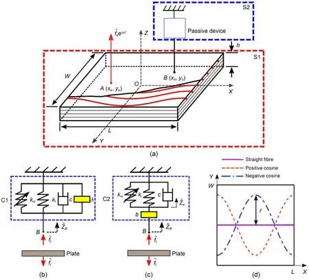
Fig.1 (a) Schematic diagram of a VAT composite plate with an inerter-based passive NES device attached; (b) NES configuration C1 (the spring,damper,and inerter are set in parallel); (c) NES configuration C2 (the spring and damper are initially set up in parallel and then linked in series with an inerter); (d) Different fiber angle functions.Reference to color refers to the online version of this figure.Explanations of variables will be given in the following sections
Fig.1d presents different fiber orientations comprising straight fiber cases shown by the solid line.The fiber placed is curved in red and blue lines; to allow the stiffness of the plate to change continuously,the function of the blue one is as described as
whererdenotes half of the amplitude,andlis the wavelength of this periodic function.It is noted that,using Eq.(1),only the direction of a single fiber-tow is considered,and no consideration is included for manufacturing constraints and defects such as gaps and overlaps.Thus,the variable fiber orientation angleθ(x) can be obtained by taking the first derivative off(x) againstx:
The first configuration (i.e.,scheme M0) is for the laminated plate for which the fiber angle for every layer is set the same.The second configuration (i.e.,scheme M1 with [+ + + +]) is for laminated plates with variable stiffness with fiber angle in each layer described by the same function expressed by Eq.(1).In the third configuration (i.e.,scheme M2 with [+ -+ -]),the plate is symmetric about theOX-OYplane.The fiber angles of the odd layers are described by Eq.(1) while those of the even layers are described by
Note that the coordinate systems used for the main material and the entire connected structure may not match.Several fiber angles can also be set for different layers of composite laminates.As a consequence,the connections between stresses and strains in one coordinate system and their equivalent values in another must be determined.
The constitutive equations of each layer are expressed as (Reddy,1997)
whereσandτrepresent the normal and shear stresses,respectively;εandγrepresent the normal and shear strains,respectively;Qijrepresent the plane stressreduced stiffnesses,which are related to the engineering constants according to
whereEis Young’s modulus,Gis the shear modulus,andvis Poisson’s ratio.
For an orthotropic material,the stress-strain relation involving the plane stress assumption is given by
where
Note that the constitutive relation is for a single lamina in global coordinates.
In the first-order shear deformation theory (FSDT),the displacements for a certain point on the plate are represented by the lettersu,v,andw,respectively,in the directions ofOX,OY,andOZ.
whereφxandφydenote rotations around theOYandOXaxes,respectively.(u0,v0,w0) are the displacement components along the (x,y,z) coordinate directions,respectively,of a point on the midplane.
The relationship between the internal forcesNor momentsMand the displacements is:
whereKis the shear correction factor,given asK=5/6.Aij,Dij,andBijdenote the extensional,bending,and bending-extensional coupling stiffnesses,respectively,which are related to the lamina stiffnessesby
2.2 Inerter-based NES device
Two kinds of passive devices are presented in Figs.1b and 1c.For configuration C1,the spring,damper,and inerter are set in parallel.In contrast,in configuration C2,the spring and damper are initially set up in parallel and then linked in series through an inerter.Linear and nonlinear springs are considered and investigated in both configurations.The displacement of the attachment pointBin theOZdirection is denoted by.The passive device is subjected to a harmonic forceby the plate.When C1 contains only the linear spring,this can be expressed as
On the other hand,when C1 is with a purely nonlinear spring representing a nonlinear energy sink,we have:
For configuration C2,when it contains only the linear spring,it follows that:
whererepresents the upper terminal of the complex displacement amplitude of the inerter.By cancelling outin Eq.(15),we can obtain:
The equation governing the dynamics of configuration C2 with a purely nonlinear spring representing a nonlinear energy sink is:
3 Dynamic analysis using the substructure method
The substructure technique is used in this work to calculate the steady-state response of the integrated system.For complex structures,obtaining comprehensive analytical solutions for the dynamic response is challenging,while the substructure method can deal with these problems at a low cost (Wang et al.,2002).In this method,the entire system is initially divided into various substructures.Then the vibration properties of the whole structure can be obtained by force balance and the continuity of displacement.Currently,when using the substructure method,the composite plate is subsystem I (S1),and the suppression device is subsystem II (S2) of the system.
3.1 Analysis of the composite plate
The receptance frequency response function is defined as the ratio between the complex amplitude(i.e.,) of the displacement of a point of interest(xr,yr) to that (i.e.,) of a concentrated harmonic force supplied at (xe,ye):
For the plate structure,the receptance function can be written as:
wheremandnare used to indicate mode numbers,μ=ρhis the mass per unit area,ρis the density,ηstands for the structural damping,and the mode shape function is represented byφmn.Note that as a plate is a continuous structure with an infinite number of modes,the modal sum will need to be truncated by varyingmandnfrom 1 to fixed values.This is reasonable; highorder modes associated with high natural frequencies will have small contribution to the response.
3.2 Solution based on harmonic balance (HB) method
Two forces are applied to the simply supported plate.One is the external excitation forceat pointAand the other isprovided by the NES suppression device located at pointB.The displacement response amplitude at pointBdue to the forceapplied at pointAis:
where
is the receptance function obtained from Eq.(19) by replacing the subscripts e and r withAandB,respectively.Similarly,the displacement response at pointBdue to a harmonic force with complex amplitudeand frequencyωapplied at pointBis expressed by
where
is the receptance function obtained from Eq.(19) by replacing the subscripts e and r both withB.Note that the negative sign in Eq.(22) is due to the direction ofbeing opposite to the positive direction of the displacement in the vertical direction.
Therefore,the combined displacement response of pointB,with contributions fromandboth with the same frequencyω,is expressed by
For the configuration C1 withoutknl,the unknown displacementand forcecan be obtained by solving Eqs.(13) and (24):
Similarly,for the configuration C2 withoutknl,the unknownandcan be obtained by solving Eqs.(16)and (24):
When the suppression devices are with both linear and nonlinear springs,the HB method is used to obtain the dynamic response by approximating the unknown displacementand transmitted forcefBtas
4 Energy-based performance index
In engineering structure design,to measure the vibration level of a structure,kinetic energy is a crucial factor (Xiong et al.,2003).At present,the maximum kinetic energy of composite plates is defined as
whereVis the velocity.
The laminated plate is subjected to a point excitation in theOZdirection and its kinetic energy is only measured in the direction of vertical motion.After completing the integration,the kinetic energy can be obtained by
The design of a composite plate requires better vibration control which means that,under the excitation force,the kinetic energy level should be as low as possible.
Based on the definition of instantaneous power flow density vector (PFDV),its time-averaged quantity over a period of excitationTcan be derived that:
whereqkis the instantaneous power flow density vector,v*jis the velocity vector,andσjkis the stress tensor,withj,k=1,2,3.
Then,the two parts of the PFDVs are introduced with a time-averaged quantity:
whereandv*represent complex conjugates of the displacements,andrepresents the complex conjugate of the rotations.
5 Results and discussion
5.1 Experimental verification and free vibration
To validate the numerical results,experimental testing was carried out to determine the natural frequencies of the structure.Constant-stiffness and VAT carbon fiber/epoxy composite plates were fabricated using the vacuum-assisted resin injection (VARI) method.The fiber used was T700SC-12000,produced by Toray with a tensile modulus of 230 GPa.The resin was 4330A1B1 made by Epotech,with a modulus of 2.9 GPa.Two unidirectional carbon fiber/epoxy constant stiffness composite plates with fiber angles of 0° and 90° were manufactured by stacking and consolidating individual prepreg sheets.For the VAT composite plate,VAT machines form the braided fabric by stitching the fiber bunches on the unidirectional fabric with the desired function shape.Four pieces of braided fabric are stacked together,and one piece of unidirectional fabric is then placed on top to ensure a smooth surface of the final product.After that,they are placed under vacuum in an autoclave and pressurized during the heated cure cycle.Finally,after the sample is cured,it is cut into a rectangular shape with a dimension of 500 mm×50 mm with a water jet.It is noted that the method is not using prepregs and focusing on the fiber angle being steered using a machine for dry fibers and then the resin is injected unlike the automated tap layer.Therefore,the manufacturing constraints do not include tape width,minimum radius,and creation of gaps and overlaps (Nik et al.,2014a; Akbarzadeh et al.,2016;Vijayachandran and Waas,2022a).
After the fabrication step,modal tests were performed on samples to obtain their natural frequencies.Fig.2 shows the hammer test configuration for a cantilever composite plate.The specific point of the structure was excited,and the force applied was measured by a force transducer installed inside the hammer.A light micro-accelerometer was placed at the centre of the outer edge of the sample to measure the data response of the plate.In addition,the accelerometer and the test sample were connected using adhesive glue to reduce the possible mass loading effect.Then,the measurement data were collected and processed by a Data Physics data acquisition instrument.The vibration response data were processed more than 10 times to ensure that the results were statistically representative.
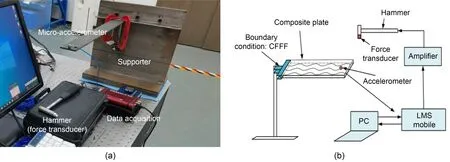
Fig.2 Installation of vibration test equipment: (a) experimental setup; (b) schematic setup.CFFF stands for boundary condition as clamped on one side when the other three sides are free; LMS stands for learning management system
The plate structure was divided into 181 elements in the finite element modeling (FEM) step,with each node having six degrees of freedom.A PC with Windows 10 operating system was used to do the calculations.The computer featured 16 GB RAM and an Intel Core i7-8750 processor of 2.2 GHz.With the properties measured by the samples and the damping ratio set as 0.01,the natural frequencies of structures could be determined.
The natural frequencies for two kinds of constant stiffness plates are compared in Table 1 using two different approaches.The error is defined as100%,wheref1andf2are the natural frequencies gained by the experimental and numerical approaches,respectively.The difference of the experimental results relative to the numerical results was less than 4%.Therefore,the vibration properties of the plate could be investigated using the numerical approach.
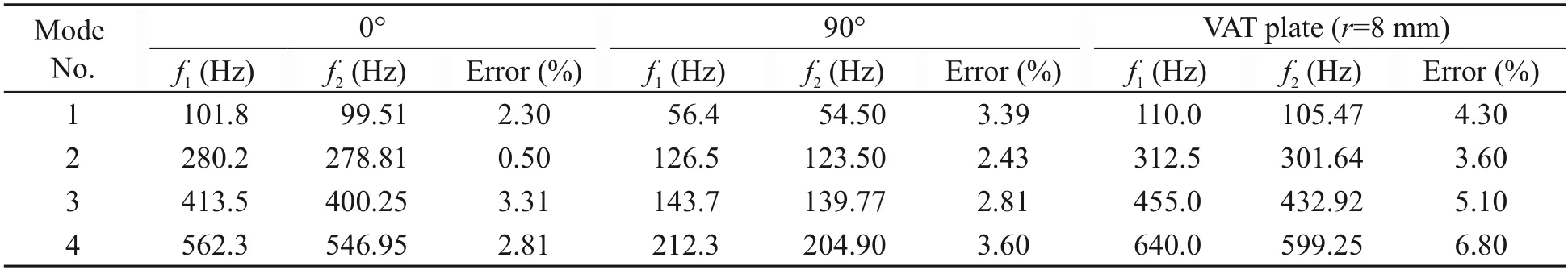
Table 1 Comparison of the natural frequencies of various composite plates with different fiber functions obtained by experimental and simulation methods
For the VAT composite plate with amplitude correlation coefficientr=8 mm,the results gained from numerical and experimental methods are listed as well.It can be found that the differences between the experimental results and numerical results are a little larger compared with those of the constant stiffness plate.That may be because the mathematical models used in the current study do not consider the movement of the fiber due to vacuum pressure,on the presumption that all fibers are precisely moved.
The free vibration performances of the VAT composite plates under the considered fiber orientations were studied.The non-dimensional natural frequenciesof the structure were established using the formulawhereω11is the natural frequencies of the structure,andE22is Young’s modulus.All edges were simply supported in the circumstances that are being shown.The parameters for the material were specified asE11=120 GPa,E22=7.9 GPa,E12=5.5 GPa,E23=1.58 GPa,v12=0.33,v23=0.022,andρ=1580 kg/m3.The dimensions of the structure are set asL=W=1 m,andh=0.01 m.As for the fiber function,the wave lengthlis constant as 1 m in this study.
Figs.3a and 3b reveals the impacts of the amplitude correlation coefficient of the fiber functionron the dimensionless natural frequencies of the VAT composite plates M1 and M2,respectively.The parameterrvaries from 0.0 to 0.5 m.The natural frequencies corresponding to the first four modes are displayed and it is revealed that the fiber function has significant impacts on the 2nd,3rd,and 4th non-dimensional frequencies.Fig.3a shows that for plate M1,the lowest value of the 1st dimensionless natural frequency at 11.90 appears whenr=0.5 m.The peak of the 2nd frequency at 26.45 is around the centre of the line,and the value is close to the minimum value in the 3rd frequency.When the parameterris increased,the 4th natural frequency firstly reduces to its lowest value at 38.23 whenr=0.1 m,then it increases.Fig.3b shows the natural frequencies of plate M2,whose fiber layers vary along its thickness,and more significant variations in the natural frequencies are found due to the change in the fiber function compared with those in M1.This time the minimum value for the 1st natural frequency appears whenr=0 m.For the 2nd frequency,when the parameterr=0.2 m,the peak frequency is at 31.00,which is larger than the highest value of the 2nd frequency in Case M1 at 26.45.Besides,the peak of the 3rd frequency in this case at 37.62 is also larger than that in the previous case.Finally,as for the 4th nondimensional frequency,when the parameterr=0.3 m,the non-dimensional frequency reaches 54.03,which is the largest value in this line.Thus,it can be concluded that the design of VAT plate M2 could further increase the natural frequency.
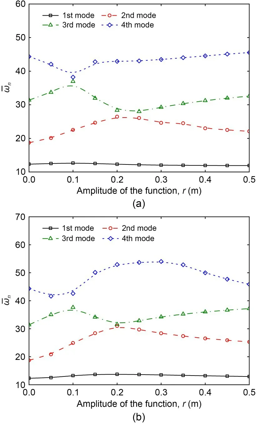
Fig.3 Effect of fiber function on the natural frequencies of the square VAT laminated composite plates with configurations M1 (a) and M2 (b)
5.2 Vibration suppression by VAT design
Here,we considered a point forceof 10 N that was applied at the centre of the lower left quarter of the plate,with a non-dimensional frequencyvarying in the range of 10 to 35.The damping ratio was set as 0.01.Then the displacement responses at the stimulation pointw,the kinetic energy of the whole plateKp,and the energy transmission path (ETP) were obtained.The effect of the amplitude correlation coefficient of shape parameterrwas investigated.An analytical method was also applied to determine the vibration response of the plate with constant stiffness,and the result was compared with the results of the VAT plate withr=0 m using the numerical method.The lines and square symbols represent the numerical and analytical results,respectively.
5.2.1 Forced vibration of configuration M1
Figs.4a and 4b show the effects of the amplitude correlation coefficient of the fiber functionronwandKpof the plate M1,respectively.The figures demonstrate good agreement between the analytical and FEM findings.Five cases were investigated with variousrof the fiber function,set as 0,0.05,0.125,0.25,and 0.5 m for Cases 1,2,3,4,and 5,respectively.Fig.4a reveals that for the displacement response,whenis changed,the displacements of the plates with variousrare very different.Each first peak in these five cases appears whenis in the range of 11.5 to 12.5.The first peak in Case 4 withr=0.25 m is the highest among all the instances with a value of 0.41 mm,while the first peak of Case 3 withr=0.125 m appears latest when the dimensionless excitation frequency reaches around 12.64.As for the second peaks in these cases,their corresponding non-dimensional excitation frequencies are very different.For Case 4 withr=0.25 m,the gap between the first and second peaks is the largest,and the second peak appears at=26.05,while for Case 1 withr=0 m,it appears when=18.75.Fig.4b shows that for the M1 configuration,the highest kinetic energy at 0.16646 J is found in Case 1 withr=0 m when=18.68.For the second peak,the energy response of Case 5 withr=0.5 m is similar to that of Case 2 withr=0.05 m,while the excitation frequency of Case 1 withr=0.05 m is lower.Furthermore,when the amplituderof the fiber function rises from 0.05 to 0.25 m,the value of the second peak decreases,and the gap between the first two peaks becomes larger.
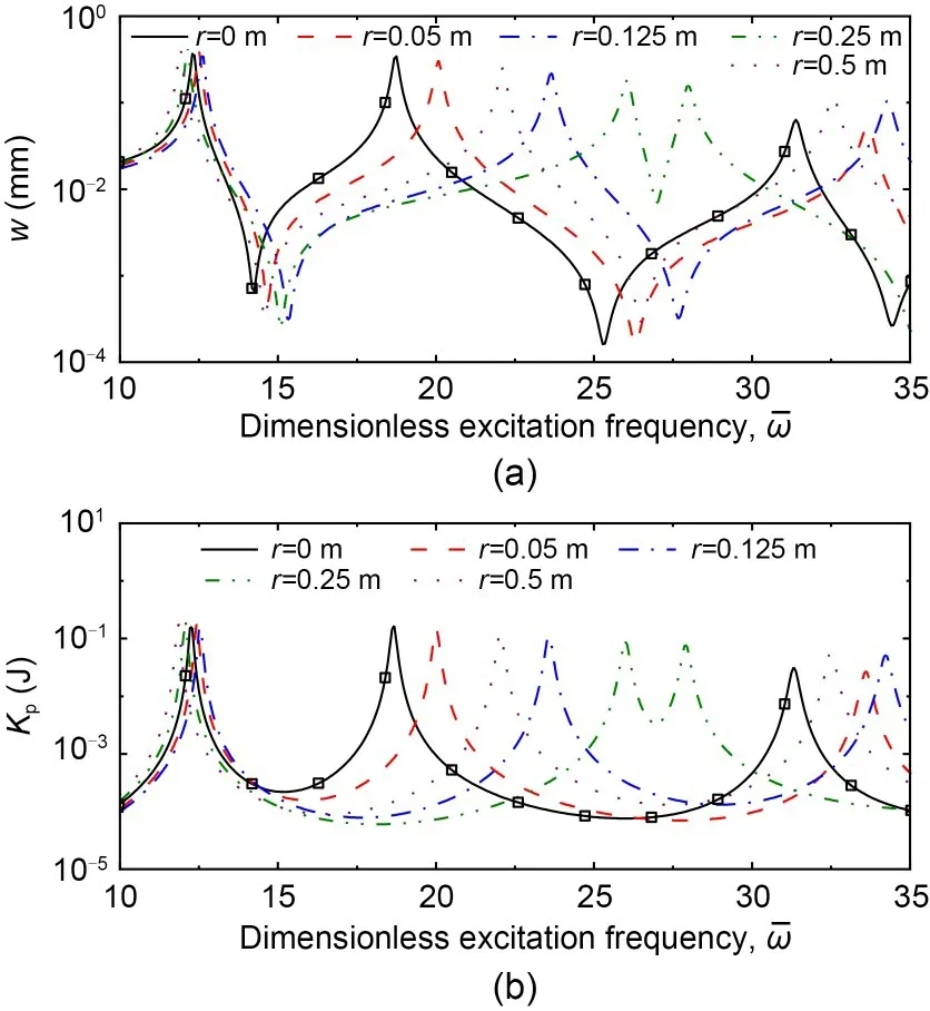
Fig.4 Effect of fiber function on the displacement (a) and kinetic energy (b) responses of square VAT laminated composite plates with configuration M1
Fig.5 shows the energy transmission paths and the dominant mode shape within the square composite plates with configuration M1 for fiber shaper=0.25 m.Three cases were considered and the non-dimensional excitation frequencies were selected as 26.06,27.99,and 43.06,which are respectively the 2nd,3rd,and 4th resonant frequencies of the plate.The figure reveals that the vibration energy transmission paths are highly influenced by the stimulating frequencies.Fig.5a shows that when=26.06,energy imported from the excitation point mainly flows upwards.In the upper middle half of the plate,the energy first flows to the lower right corner and then to the upper right corner.Afterwards,in the right-hand side (RHS) of the plate,all the energy flows downwards,and the contour line in Fig.5a becomes heart-shaped.Fig.5d shows its corresponding dominant mode shape: there are two bending wave forms with one curved nodal line.Moreover,it can be seen from Figs.5a and 5d that the directions of PFDVs on the nodal line are roughly perpendicular to the nodal lines.The energy transmission paths in M1 when it is activated at the third resonance frequency and its associated dominant mode shape are presented in Figs.5b and 5e,respectively.Fig.5b shows that the transmission pattern of the energy is similar to that in Fig.5a,while the response level is higher here.Besides,Fig.5e demonstrates four wave forms with a curved nodal line and the PFDVs on the nodal line point to the upper right and lower left corners,which are almost perpendicular to the nodal line.The vibration responses of M1 excited at its fourth resonance frequency are shown in Figs.5c and 5f.Fig.5c reveals that in the LHS of the structure,some energy input from the excitation point flows upwards and then to the right,and some energy flows downwards firstly and then also to the right.Besides,a sink is found near the top right corner of the plate.In general,the energy transmission path is similar to a square.On the other hand,Fig.5f shows four wave forms in the plate,which are located at four corners of the plate,and the contour lines are all broadly oval in shape.
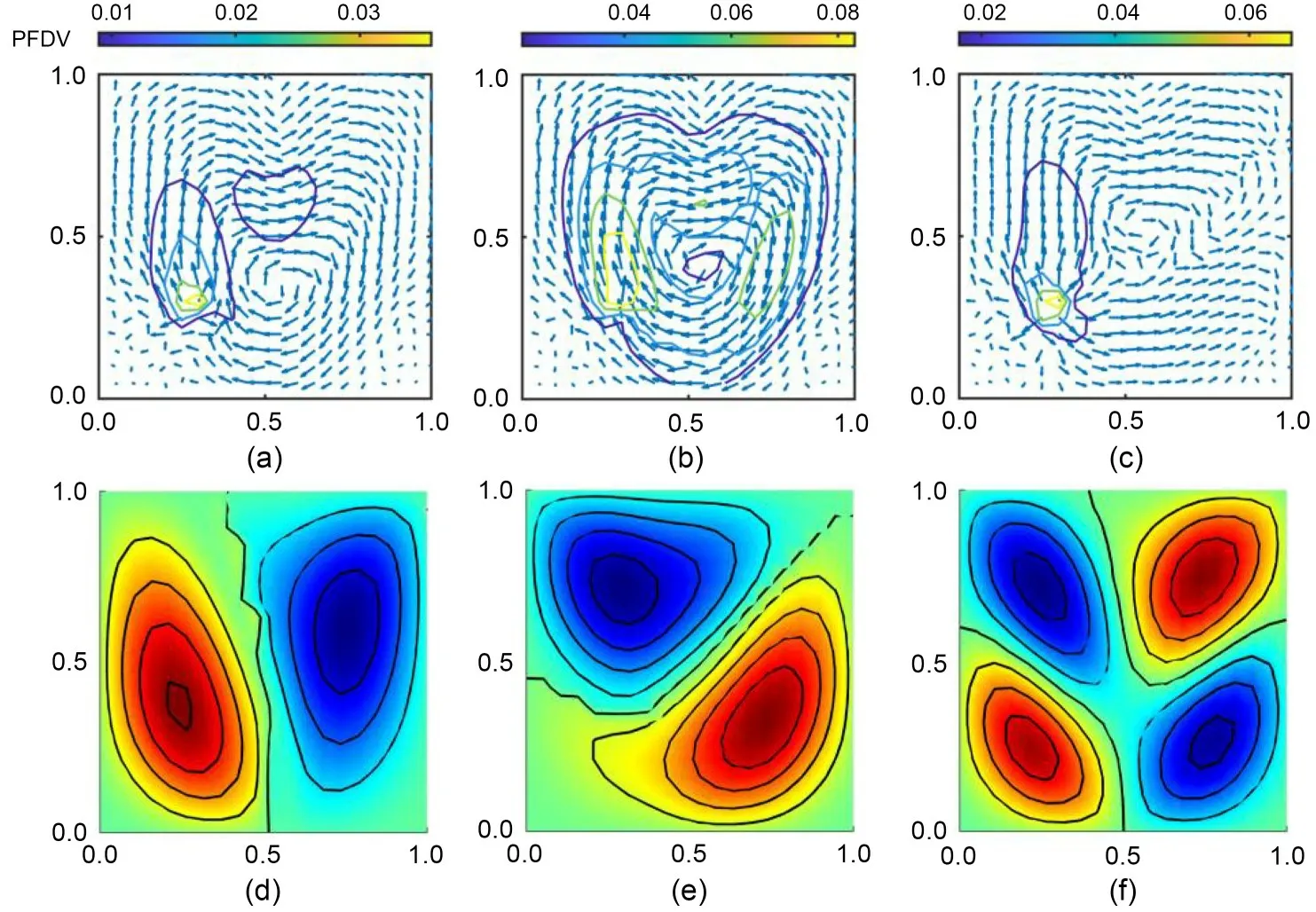
Fig.5 Energy transmission paths with =26.06 (a),=27.99 (b),and =43.06 (c) and the second (d),the third (e),and the fourth (f) mode shapes within square VAT composite plates under M1 configuration with fiber shape r=0.25 m
Fig.6 shows the ETPs and the corresponding dominant mode shapes within the square composite plates under M1 configuration and different fiber parameters,r,which are set as 0.05,0.25,and 0.50 m for Cases 1,2,and 3,respectively.The excitation frequency,=20.07,was selected for three cases,where significant variations in theKpwere found in Fig.4b.The external force evidently feeds a significant amount of energy into the plate.Under the same stress condition,the responses of the plate are significantly different because of the change in fiber function.Fig.6a reveals that for Case 1 withr=0.05 m,whose fiber orientation is near 0°,the vibration energy is input from the excitation point.Around the excitation point,the main energy flows to the upper right corner,and some energy flows to the upper left corner.Furthermore,in the upper half of the plate,all the energy flows upwards vertically and then converges to a sink found at the midpoint of the upper edge.In addition,the matching dominant mode shape is shown in Fig.6d,which demonstrates that there are two wave forms in total,with two bending waves in the direction ofOYand one bending wave in the direction ofOX.There is also a curved nodal line found near the centre of the structure.According to Figs.6a and 6d,it is clear that the PFDVs on the nodal line are pointing straight upwards,perpendicular to the nodal line.Fig.6b demonstrates the ETPs within the plate under M1 configuration whenr=0.25 m.It is revealed that in the LHS of the plate,the vibration energy mainly first flows upwards and then flows to the right.In contrast,in the RHS of the plate,the energy flows to the upper right corner and to the sink generated at the upper half of the right edge.Fig.6e presents its corresponding dominant mode shape,and it is evident that there are two wave forms in the diagonal corners and a curved nodal line.The ETPs within the plate withr=0.5 m and the dominant mode shapes are presented in Figs.6c and 6f,respectively.Based on Fig.6c,it is found that in the LHS of the plate,the energy transmission pattern is similar to that in Fig.6b,while in the RHS,the energy mainly flows to the right and converges to a sink around the point (1.00 m,0.25 m).Two wave forms with two bending waves in theOXdirection can be seen in the structure in Fig.6f.Besides,a curved nodal line is found,and the PFDVs on this line point to the right,roughly perpendicular to the nodal line.
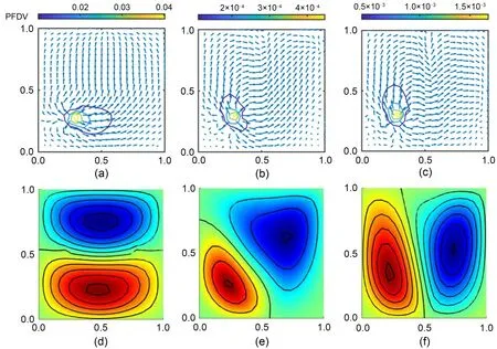
Fig.6 Energy transmission paths with different fiber shapes r=0.05 m (a),r=0.25 m (b),and r=0.5 m (c) and the corresponding second mode shapes (d)-(f) within square VAT composite plates under configuration M1 excited at =20.07
5.2.2 Forced vibration of configuration M2
Figs.7a and 7b reveal the impacts of amplitude correlation coefficientrof the fiber function on thewandKpof the VAT plate M2,respectively.Five cases were investigated with differentrvalues,including 0,0.05,0.125,0.25,and 0.5 m for Cases 1-5,respectively.The analytical and FE findings exhibit good agreement.Fig.7a shows thewof plate M2 under various non-dimensional excitation frequencies.Among all the cases,the first peak appears in Case 1 withr=0 m when the non-dimensional excitation frequency=12.29,and the value there is 0.3658 mm.After comparing the first peak in each case,the highest peak,at 0.371 mm,is found in Case 2 withr=0.05 m,when=12.57,while in Case 4 withr=0.25 m,the value of its first peak is only 0.314 mm.Whenr=0.25 m,the gap between the first two peaks is the largest compared with other cases.Fig.7b depicts theKpof plate M2.In these five cases,the highestKpat 0.1822 J is found in Case 5 withr=0.5 m,followed by that in Case 2 withr=0.05 m,when the non-dimensional frequency=12.50.In addition,as for the first peak in each case,the lowestKpat 0.1446 J is found in Case 4 withr=0.25 m,when=13.55.For the second peak,when the amplitude correlation coefficientrof the fiber function increases from 0.05 m to 0.25 m,the value of the second peak decreases,and the gap between the first two peaks is larger.Whenis between 10 and 35,there are only two peaks in all cases except Case 1 withr=0 m and Case 4 withr=0.25 m.
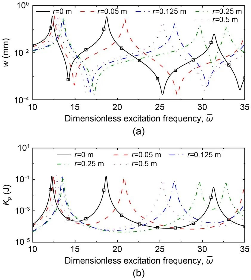
Fig.7 Effect of the fiber function on the displacement (a)and kinetic energy (b) responses of square VAT laminated composite plates with configuration M2.The lines and square symbols represent the numerical and analytical results,respectively
Fig.8 shows the ETPs and corresponding dominant mode shapes within the composite plates under configuration M2,with the amplitude correlation coefficient of fiber functionr=0.25 m.Three cases are studied here with different non-dimensional excitation frequencies; these are chosen as 29.71,32.87,and 53.68,which are the 2nd,3rd,and 4th natural frequencies of the structure,respectively.Fig.8a shows the ETPs within plate M2 excited under the 2nd natural frequency.It is revealed that the main energy import from the excitation point flows upwards and then to the upper right corner.In contrast,in the RHS of the plate,the energy first flows to the lower right corner and then to the lower left corner.Compared with Fig.5a under M1,the response level here in Fig.8a is lower,which means that such a plate with configuration M2 can somewhat suppress the vibration.Fig.8d displays the form of the dominant mode,where the structure has two wave forms.Two bending waves are present in the direction ofOX,while one is present in the direction ofOY.Moreover,in areas close to the center of the plate,there is a curved nodal line.Fig.8b shows the ETPs within the plate,when=32.87.It can be seen that the transmission pattern of the energy here is similar to that in Fig.8b,and the contour line is approximately circular.Fig.8e presents the corresponding dominant mode shape.Four wave forms and a curved nodal line are found in the structure.Based on Figs.8b and 8e,the PFDVs on the nodal line are approximately perpendicular to the nodal line in their direction.The ETPs within the plate excited at its fourth natural frequency are determined in Fig.8c.Some vibration energy imported from the excitation point flows upwards vertically and then to the right to a sink located at the top right corner of the structure.On the other hand,some energy flows to the right and then flows upwards.A total of four wave shapes can be seen in Fig.8f,with two bending in theOXdirection and two bending in theOYdirection.Nodal lines are also shown in the figure.The PFDVs on nodal lines point horizontally or vertically,both of which are almost perpendicular to the nodal line.Based on Fig.8,it can be concluded that the vibrations of ETPs within the plate are affected by the frequency of the excitation sustainably.
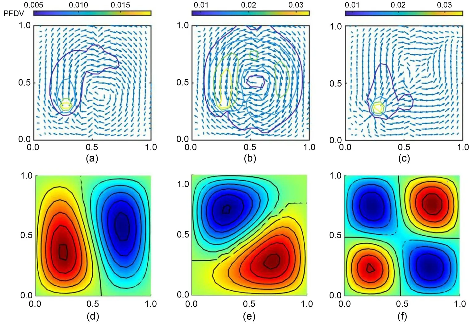
Fig.8 Energy transmission paths with =29.71 (a),=32.87 (b),and =53.68 (c) and the second (d),the third (e),and the fourth (f) mode shapes within square VAT composite plates under M2 configuration with fiber shape r=0.25 m
Fig.9 shows the ETPs and the corresponding dominant mode shapes within square composite plates under M2 configuration with different fiber function parametersrof 0.05,0.25,and 0.50 m.These three plates were all excited at=20.85,where the large differences in terms of theKpwere found in Fig.7.Fig.9a reveals the ETPs within the plate underr=0.05 m,where the vibration energy is imported from the excitation point.Much energy flows to the right and then upwards.Besides,in the upper half of the structure,all the energy flows upwards vertically and then converges to the sink found at the midpoint of the upper edge.As for the corresponding dominant mode shape,Fig.9d shows two wave forms in the structure with two bending waves in theOYdirection.A horizontal nodal line is located at the centre of the structure.It is evident that the PFDVs on the nodal line are pointing upward vertically,which is nearly perpendicular to the nodal line.On the other hand,whenr=0.25 m,the ETPs within the plate are shown in Fig.9b.It can be seen that in the LHS of the plate,the main energy first flows to the upper right corner and then to the lower right corner,while in the RHS of the plate,all the energy flows to the upper right corner to a sink that is found near the point (0.9 m,0.8 m).Fig.9e shows three wave forms in the plate with a curved nodal line.As for the plate withr=0.5 m,Fig.9c reveals that in the LHS of the plate,the transmission pattern of the energy is similar to that in Fig.8b.In contrast,in the RHS of the plate,the energy firstly flows horizontally to the right,then it converges to the sink that is situated in the centre of the right edge.Fig.9f displays the dominant mode shape of the plate withr=0.5 m.It is revealed that there are three wave forms and a curved nodal line.Additionally,it is discovered that PFDVs on the nodal line are oriented horizontally to the right and are roughly perpendicular to the nodal line.Based on Fig.9,it can be concluded that under the same condition of excitation stress,the fiber function has a considerable impact on the responses of the plate.
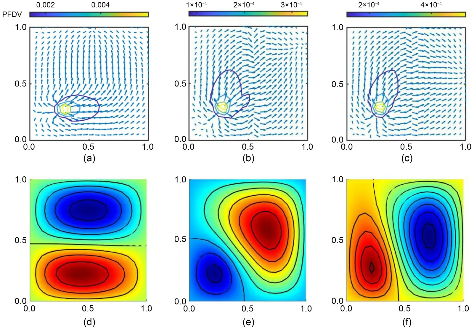
Fig.9 Energy transmission paths with different fiber shapes r=0.05 m (a),r=0.25 m (b),and r=0.5 m (c) and the corresponding second mode shapes (d)-(f) within square VAT composite plates under M2 configuration excited at =20.85
5.3 Vibration suppression by attaching a passive device
In addition to the change of fiber function,attaching a passive device can also suppress the vibration response of the plate.To this end,the centre of the bottom left quadrant of the plate was subjected to a point forceof 10 N,and the non-dimensional frequency of this forcevaried from 5 to 35.The damping ratio was assumed as 0.01.The substructure method was used,and the kinetic energyKpand the ETPs were both focused on.We studied two different passive devices C1 and C2 installed at the upper right quarter of the plate,and the effect of the nonlinear device was also investigated.
5.3.1 Forced vibration of configuration M0
Fig.10 shows the effect of coefficients of the spring and damper on theKpof the constant-stiffness structure M0 with fiber angleθ=0°.The forced response was also calculated using an analytical technique and the outcomes were contrasted with those obtained using the numerical method.The lines and symbols represent the numerical and analytical results,respectively.Based on the result,good agreements between the analytical and FE results could be found.Fig.10 reveals that when the coefficient of the passive device is changed,the kinetic response of the plates is also very different.It is shown that among the three cases,the highest peak at 0.3131 J appears in Case 3 withk=1×10⁷N/m andc=500 N·s/m,when=14.04.As for Case 2 withk=1×10⁶N/m andc=200 N·s/m,the corresponding excitation frequency is similar to that in Case 1,while the level of the kinetic energy is increased to 0.14374 J,which means that the decrease in the coefficient of the damper can increase the response of the structure.The peak of Case 3 withk=1×10⁷N/m andc=500 N·s/m appears the last,due to which the increase of the coefficient of the spring can move the peak to the right.
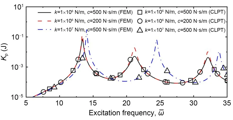
Fig.10 Effect of the passive device (spring and damper in parallel) on the Kp of the composite plate under M0 configuration,with fiber angle θ=0°,attached to the passive device at point B (0.75 m,0.75 m).CLPT: classical laminated plate theory
5.3.2 Forced vibration of configuration M1
Figs.11 and 12 respectively show the effects of linear and nonlinear passive device C1 on theKpof the plate under M1 configuration with the amplitude correlation coefficient of the fiber functionr=0.25 m.Fig.11a demonstrates that the spring may substantially impact the kinetic response of the plate.Underc=500 N·s/m andλ=1,it is evident that the peaks of kinetic energy curves are pushed to higher frequencies as the spring stiffness increases.Compared with that in the plate withk=1×10⁵N/m,the non-dimensional resonant frequency in the plate withk=1×10⁷N/m is increased from 9.06 to 14.04.Moreover,a reduced elevation of the kinetic energy of the plate in the lowfrequency range with<8.64 may also result from the stiffness of the attached spring.Fig.11b shows the effect of the damper; the coefficients of spring and inerter were set ask=1×10⁵N/m andλ=1,respectively.Based on the result,it is evident that increasing the damperccould lower the maximum values ofKp.For example,when the damperc=1000 N·s/m the peak value is only 8.19×10⁵J,which is around 0.9% of that in the plate without the damper.However,it is noted that the impact of damper on the vibration level of the plate will be minimal if the stimulation frequency is not within the resonant areas.Fig.11c demonstrates the effect of the inerter,with the setting for the spring and damper coefficients atk=1×10⁵N/m andc=500 N·s/m,respectively.The first peaks in theKpcurves move to lower frequencies when the coefficient of the inerter is increased,and the value of the peaks is also reduced.It is also found that whenis in the range from 10 to 13,the attachment of the inerter can decrease the responses.Fig.12 shows the effect of the nonlinear passive device C1 on the plate,with the coefficients of the devices set ask=1×10⁶N/m,c=500 N·s/m,andλ=0.1.It is revealed that attaching the nonlinear device decreases the resonant frequency compared with the plate without the passive device.Among these three cases,the value of the first peak in the case with the nonlinear device is the lowest at 0.00292 J.
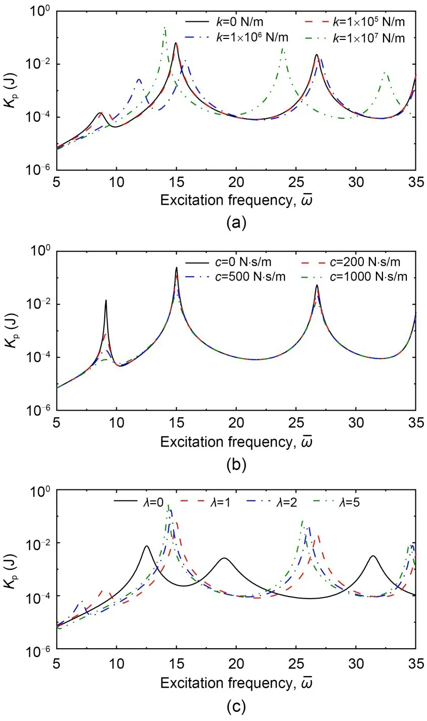
Fig.11 Effect of passive device C1 (in-parallel) on the Kp of VAT plate under M1 configuration with fiber function r=0.25 m,attached to the passive device at point B (0.75 m,0.75 m): (a) c=1000 N·s/m,λ=0.3; (b) k=1×10⁵ N/m,λ=0.3;(c) k=1×10⁵ N/m,c=1000 N·s/m
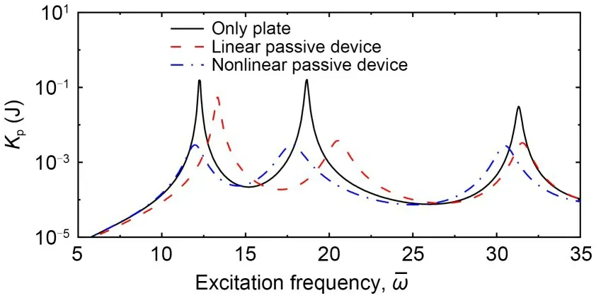
Fig.12 Effect of linear and nonlinear inerter-based passive device C1 (in-parallel) on the Kp of VAT plate under M1 configuration,attached to the passive device at point B(0.75 m,0.75 m).The parameters are set as r=0.25 m,k=5×10⁶ N/m,c=500 N·s/m,and λ=0.5
Figs.13 and 14 respectively illustrate the effects of linear and nonlinear passive device C2 on theKpresponse of the plate M1 withr=0.25 m.Various coefficients of the spring,damper,and inerter were studied.Underc=1000 N·s/m andλ=0.3,Fig.13a shows that changing the spring stiffness can significantly influence the kinetic response of the plates and,when the spring is installed,one more peak appears whenis in the range of 10 to 17.It is clear that among the first peaks in each case,the lowest value at 0.00041 J appears for the plate withk=1×10⁵N/m,when the nondimensional excitation frequency=10.32.Besides,with the stiffness of the spring rising from 5×10⁵to 5×10⁶N m,the corresponding non-dimensional frequencies of the second peaks of these cases are larger,and the values of these peaks become higher.On the other hand,the effect of the damper is seen in Fig.13b,and the coefficients of the other two elements are set ask=105N/m andλ=0.3.It is found that the first peaks of all studied examples decrease as the damping coefficient increases.To be specific,compared with that for the plate without the damper,the damper withc=400 N·s/m can reduce the peak value from 0.0345 to 0.0045 J.Such evident decline is also found in the second peak region.Fig.13c demonstrates the effect of the inerter,and the settings for the spring and damper coefficients arek=1×10⁵N/m andc=1000 N·s/m,respectively.Similar to the damper,the differences caused by various inerters here are mainly reflected in the response value,rather than the resonance frequencies.With the increase in the coefficient of the inerter from 0.1 to 0.3,the first peak in each case shifts right to the higher frequencies,and the value of peaks is reduced.As for the second peak in all cases,the corresponding dimensionless frequency of Case 4 withλ=0.4 is the highest at 18.40.Fig.14 shows the effect of the nonlinear passive device C2 on the plate,with the coefficients of the devices set ask=5×10⁶N/m,c=500 N·s/m,andλ=0.5.It is revealed that among the three cases studied here,the value of the first peak in the case with the nonlinear device is the lowest at 0.0136 J.At the same time,attaching the nonlinear passive device would decrease the corresponding dimensionless frequency of the first peak when compared with a plate without the device.
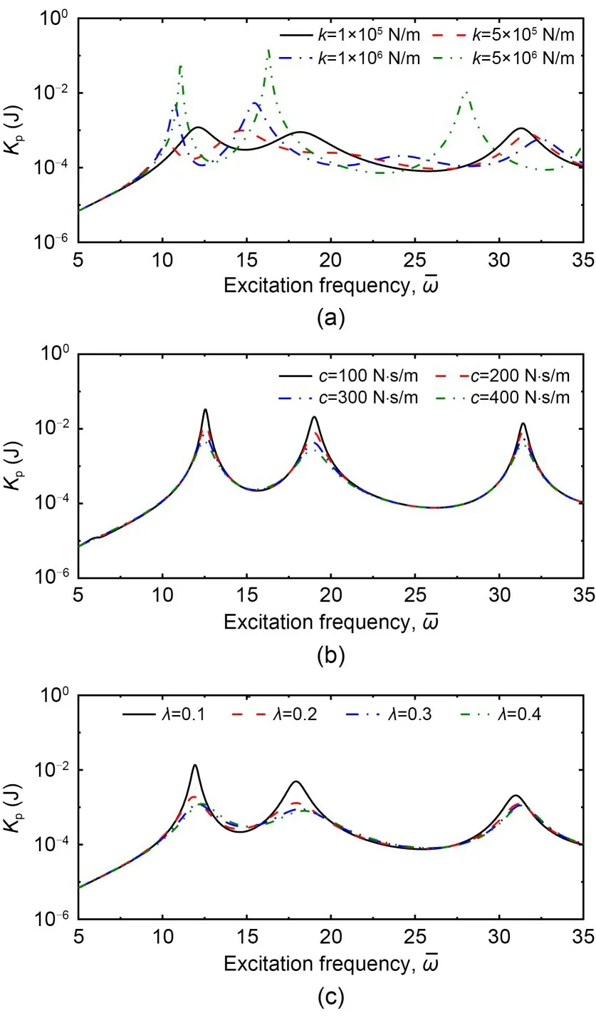
Fig.13 Effect of passive device C2 (in-series) on the Kp value of VAT plate under M1 configuration with fiber function r=0.25 m,attached to the passive device at point B(0.75 m,0.75 m): (a) c=1000 N·s/m,λ=0.3; (b) k=1×10⁵ N/m,λ=0.3; (c) k=1×10⁵ N/m,c=1000 N·s/m
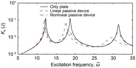
Fig.14 Effect of linear and nonlinear inerter-based passive device C2 (in-series) on the Kp value of VAT plate under M1 configuration,attached to the passive device at point B (0.75 m,0.75 m).The parameters are set as r=0.25 m,k=5×10⁶ N/m,c=500 N·s/m,and λ=0.5
6 Conclusions
This paper investigated the vibration properties of composite plates with variable stiffness laminated with passive devices.First,the substructure methods based on the numerical FE and analytical approaches were developed.In this method,the whole FE of the entire structure is not necessary,and the results may be easily obtained by changing the parameters of the receptance function,which lowers the computing costs.Using the substructure-based PFA method,the vibration performances can be quantified.Then,the natural frequencies of structures were determined and the displacement,kinetic energy responses and energy transmission paths were also analyzed using the PFA method.The influences of fiber scheme and various passive devices on the vibration performances of the structure were examined.The above techniques can aid in improving our understanding of the vibration characteristics of composite structures,allowing for the design of structures that perform better at vibration suppression.
In this work,two kinds of VAT composites with different fiber shape schemes were investigated for their vibration properties.The natural frequencies of the composite plate were shown to be significantly impacted by the fiber function.We examined the effect of the fiber function on the displacement and energy responses of the VAT plate and found that the fiber function could change the value of response peaks and the corresponding non-dimensional excitation frequencies.Furthermore,ETPs and the dominant mode shapes within the structure with two various fiber schemes were drawn.The main ETPs correlated well with the dominant mode shape.It was demonstrated that the ETPs and mode shapes were altered to a large extent by adjusting the fiber layer scheme of the plate.The results illustrated the capability of adjusting the fiber function of VAT plates to raise their vibration suppression levels.
Subsequently,the effects on the forced vibration response from adding various inerter-based passive devices were studied.The spring,damper,and inerter elements were used in combination to build the inerterbased passive devices,and both linear and nonlinear springs were considered.With the devices applied,the peak value and the corresponding frequencies were changed significantly,showing advantages for vibration suppression.When the inerter was connected in parallel or series with the spring and damper,the two alternative configurations did not function similarly.By varying the coefficients of the device,the effect of each element was better understood.Besides,compared with a passive device containing the linear spring,the vibration suppression ability of the device with a nonlinear spring was much stronger in terms of the peak value.Overall,the findings demonstrated that after composite laminates had been designed and manufactured,their vibration suppression performance could be enhanced further by attaching passive devices.
Acknowledgments
This work is supported by the National Natural Science Foundation of China (Nos.12172185,U1809218,and U1864211),the Zhejiang Provincial Natural Science Foundation of China (Nos.LY22A020006,LD22E050011,and LQ23A020003),the Ningbo Municipal Natural Science Foundation of China (No.2022J174),and the Ningbo Key Projects of Science and Technology Innovation 2025 Plan (No.2021Z124).
Author contributions
Jian YANG designed the research.Chen ZHOU processed the corresponding data.Chen ZHOU wrote the first draft of the manuscript.Jian YANG and Chendi ZHU helped to organize the manuscript.Jian YANG and Yingdan ZHU revised and edited the final version.
Conflict of interest
Chen ZHOU,Jian YANG,Yingdan ZHU,and Chendi ZHU declare that they have no conflict of interest.
 Journal of Zhejiang University-Science A(Applied Physics & Engineering)2023年8期
- Journal of Zhejiang University-Science A(Applied Physics & Engineering)的其它文章
- Research on the sampling performance of a new bionic gravity sampler
- Effects of potassium channel blockage on inverse stochastic resonance in Hodgkin-Huxley neural systems
- Numerical study of wheel-rail adhesion performance of new-concept high-speed trains with aerodynamic wings
- Co3O4-ZnO/rGO catalyst preparation and rhodamine B degradation by sulfate radical photocatalysis
- Determination of the dynamic characteristics of locomotive drive systems under re-adhesion conditions using wheel slip controller