
Effects of connection types and elevated temperature on the impact behaviour of restrained beam in portal steel frame
2023-07-31 13:30:52YuXuGuoFengXiYingHuaTanFengLiuYaChaoHu
Defence Technology 2023年7期
Yu-Xu Guo ,Feng Xi ,* ,Ying-Hua Tan ,Feng Liu ,Ya-Chao Hu a,
a School of Civil Engineering, Shandong Jianzhu University, Jinan, 250101, PR China
b Shandong Provincial Key Laboratory of Civil Engineering Disaster Prevention and Mitigation, Shandong University of Science and Technology, Qingdao,266590, PR China
c Key Laboratory of Building Structural Retrofitting and Underground Space Engineering, Shandong Jianzhu University, Jinan, 250101, PR China
Keywords:Restrained beam Connection Temperature Impact Failure modes Internal force mechanism
ABSTRACT Based on the background of structural protection and Disaster Reduction Engineering,the dynamic behaviour and failure mechanism of restrained beams in portal steel frames in localised fire are investigated via experimental measurement and numerical simulation techniques.Comprehensive parametric studies are carried out to discuss the influence of end connection types,temperature,impact velocity,impact mass and span-to-depth ratio(SDR)on the dynamic response of the beams.The characteristics of deformation,internal force and energy distribution about the restrained beams and its joints are investigated.A temperature dependent criterion for evaluating the frame joint performance is proposed to measure the degree of performance degradation and impact resistance of the joint.The dynamic displacement amplification factor in different temperature environments are proposed for the different beam end constraint types and SDRs.Results of the experimental and numerical analysis show that the welded connection (WC) of three typical joint types is the strongest,and the extended endplate connection(EEC)is the weakest in terms of the impact resistance performance.With regard to the failure mode of the joint,the failure positions of the WC and the welded-bolted connection are located in the inner web of the column.Meanwhile,the EEC is located in the connection position between the beam and the endplate.Three different internal force stages and two obvious critical temperature boundaries of the restrained beams emerge with the increase in temperature,and they have significant characteristics in terms of deformation trend,internal force transfer and energy distribution.During the impact,a phenomenon known as “compression arch action” develops into “catenary action” with the increase in deflection in the frame beam mechanism.
1.Introduction
Concerns regarding the design of structures to withstand fire and blast have intensified after the “9·11” event in the USA.The Federal Emergency Management Agency,in conjunction with the American Society of Civil Engineers,highlighted in the accident investigation report [1] that ‘the performance design of steel frames under the combined effects of fire,explosion and impact should be undertaken’.The dynamic response and failure behaviour of structures under extreme loads,such as fire,explosion and impact,are essential in the study of the performance of steel structures,which can be seriously affected by these extreme loads.
Recently,the study of steel structures subjected to distinct extreme loads (e.g.fire and impact) has attracted considerable attention.Studies on the fire[2-4] and impact [5-7] resistance of single components,such as steel beam [8,9],column and plate[10,11],have been extensively investigated.A number of scholars worldwide have discussed the fire resistance of steel frame structures through various methods,such as experiments and numerical simulations.Zhao and Kruppa[12]investigated the overall stability of steel frames subjected to fire via several fire tests.The relevant parameters were analysed by numerical simulation.Chen and Wang [13] proposed the three numerical simulation modelling methods for studying steel frames exposed to fire,and their strengths and weaknesses were also discussed.The importance of joints for steel frame resistant fire performance cannot be extensively emphasised.A large number of numerical analytical models on steel frame bolt nodes are used to investigate the fire resistance of structures under the influence of different bolt diameters,bolt strength ratings,endplate dimensions and strengths[14].Lindberg and Pedersen [15] focused on examining the plastic dynamic response of portal frame through drop hammer experiment and numerical simulation in the study of the impact resistance of steel frame structures.The influence of certain key parameters,such as connection type,impact location,flange thickness and span-todepth ratio (SDR),on the load carrying mechanism,load carrying capacity,damage mode and energy absorption of steel frames has been highlighted[16-18],suggesting that the SDR of the beam has a great influence on the impact resistance of steel frames.
At present,research on the structural behaviour under the combined action of extreme loads,such as fire,impact and explosion,is still in the development stage.Accordingly,only a small number of relevant studies have been published.Liew et al.[19-22]conducted a study associated with the behaviour of a multi-storey 3D steel frame structure subjected to fire following an explosion.They also analysed the interaction effects of explosion and fire in steel structures via numerical simulation.Liew and Chen [23]suggested a hybrid element method for the analysis of steel frame structures subjected to fire following a local explosion to investigate the ultimate load carrying capacity of multi-storey steel frames and steel columns.Sun et al.[24] investigated the blast resistance and local damage analysis of steel tubes after being exposed to fire by experimental methods.Forni et al.[25,26] investigated the strain rate effect of S355 steel at high temperatures through SHTB experiments,identified the parameters associated with the J-C constitutive model and examined the blast response of steel columns in fire.The structural response to fire and impulsive load can be catalogued by the following two cases: (a) impulsive load followed by a fire(IFF)and(b)impulsive load during a fire(IDF)[27].In the IFF case,the duration of action of the explosive or impact load is much shorter than that of the fire,and no significant coupling effect was observed between the two loads.Scholars worldwide can possibly investigate this case by decoupling the thermal and dynamic responses.The IDF case showed a relatively complex coupling effect compared with the IFF case.The strain rate effect at high temperatures is one of the most significant challenges,and the effect of thermal expansion on the mechanical properties of the material must be taken into account.Relevant research needs to be supplemented and improved.
However,experimental research and in-depth parameter analysis on the dynamic behaviour of structures under the combined action of fire and impact loading are scarce,which is the motivation for this study.Currently,the main criterion for evaluating the joint performance is the rotational angle under static load(FEMA-355D;AISC-360).To the author's knowledge,there is no report on the relevant methods to evaluate the joint connection performance under impact load and the influence of temperature effect.
In this study,experiments and numerical simulation had been carried out to investigate the failure modes and impact resistance of three common joint types of restrained beams subjected to impact following a localised fire.A novel temperature-dependent criterion for effectively evaluating the degree of degradation of joint performance was proposed.The deformation of restrained beams and their characteristics during deformation,such as internal forces and energy,had been analysed in detail to examine the influence of joint types,temperatures and SDRs,impact velocity and impact mass on the dynamic response.The failure processes and mechanisms of the restrained beams had been extensively explored through finite element(FE)analysis to better understand the response behaviour and connection performance of restrained beams subjected to impact loading during a fire.The values of the dynamic displacement amplification factor in different temperature environment are suggested for the impact protection design of steel structures with different beam end constraint types and SDRs.Moreover,the structural dynamic response characteristics of restrained beams in fire are discussed and compared in detail to ambient temperature.The significance of the above work was to integrate structural behaviour in engineering with theoretical studies for future research on structural behaviour theory and refinement of safety and security design guidelines.
2.Experiment presentation
2.1.Structural model of the impact experiment at an elevated temperature
The present test design is inspired by the pioneering work on the steel frame by B.Lindberg[15],in which a one-story steel frame with rectangular cross-section members are used and only impact loading is considered.The present study aims to investigate the characteristic response of the steel frame when subjected to combination of fire and impact loading.Therefore,considering the feasibility of the experiment and avoiding the influence of more factors,the single-story structure is the optimal choice in the initial stage of exploring effects of such complex loads.In spite of this,to closer to the practical situation,I-shaped section of members and three types of connections wield used in current practical engineering are adopted in present test model.
Referring to the impact experiment of the portal frame model discussed in Ref.[15],a steel frame structure(Fig.1)is made up of a beam and two columns and their connections.The three different typical connections shown in Fig.2 are considered.Rigid connections (RC) include welded connection (WC) and welded-bolted connection (WBC),which are the welding technique and the combination of bolting and welding technique,respectively.The extended endplate connection (EEC) is regarded as a semi-rigid connection (SRC) that uses a combination of bolting and welding techniques.These three types of connections are widely used in engineering practice.These three connections with different rotational stiffness mean different end constraints.Therefore,they can be applied to reflect the end restraint effect of adjacent structures on the frame beam.The portal frame in Fig.1 is a sub-structure.On the one hand,the columns and connections in the structure reflect the translational and rotational restraint effects on the beam ends.On the other hand,the frame beam is a more general end elastic restrained beam.

Fig.1.Simple portal frame subjected to fire and impact loading.

Fig.2.Details of the beam-to-column connections: (a) WC;(b) WBC and (c) EEC.
The two steel columns and the connecting joints are assumed to be protected from fire,so only the beam heats up in the event of a fire in the room.When the frame beam reaches a certain temperatureT,it is subjected to impact by the upper falling layer.MassMis assumed to impact the central section of the beam with velocityvo.The temperature is assumed to be constant because the impact process is short (in ms).The portal fame is characterised by the overall heighthoand lengthlo,and the cross-sectional dimensions are shown in Fig.1.
2.2.Experimental program
The dynamic behaviour of portal steel frame structures in fire subjected to impact loading was investigated at elevated temperatures via drop hammer impact experiments (Fig.3).The device used in the experiments is made up of several systems,including a heating system,a drop hammer impact machine and a recordacquisition system.Three sets of components,namely,seven specimens,were employed in the experimental design scheme.The drop hammer has a mass 137 kg and fell from 7.2 m.The impact face is semi-circular with a radius of 12.5 mm and 80 mm width orthogonal to the beam axis.The overall height of the columnhoand the span length of the specimens between two columnslowere 0.9 m and 1.6 m,respectively.During the experiment,the 10# Ibeam was applied to the steel beams and columns,which were made of Q235B.Grade 8.8 M12 high strength bolts were used for connection in the specimen.The details of the connections and dimensions are shown in Fig.2.During the impact test,stiff restraint beams are placed in front of and behind the upper section of the column to prevent the out-of-plane deformation of the frame column as shown in Fig.3.The temperature is monitored by thermocouple to reach the established temperature.

Fig.3.Experimental set-up:1 traction chains,2 counterweight blocks,3 hammerhead,4 directional track,5 RHC,6 moving track,7 support base,8 track-supporter,9 bolts for fixing the base,10 steel frame specimen,11 heating system and 12 stiff restraint beams.
The experiment was carried out according to the following steps:
(a) The steel frame was fixed to the support base of the experiment bench by bolts.
(b) The frame beam was placed in the resistive heating chamber(RHC),and asbestos was used to wrap the inner wall of the RHC for insulation.The heating process follows the ISO-834 standard fire curve.
(c) Thermocouple temperature sensors were used to monitor the temperature of the steel beams in real time.Once the temperature reached the specified value (20°C,400°C and 800°C),the RHC was unlocked and removed along the moving track as soon as possible.
(d) The drop hammer was released by the loosening control clamps after the anti-disengagement safety device had been suspended.The beam was subjected to impact of the drop hammer at the middle span.
During the experiment,several calibrated high-speed cameras were employed to capture the process of the impact.After the experimental steps were completed,the final deformation of the steel frame structure was determined by traditional measurement methods to support the results of the high-speed camera.
2.3.Experimental results
The experimental stages of portal steel frame structure subjected to extreme load mainly consists of two loading process phases,namely,static heating stage and impact response stage when reaching a certain temperature.It should be noted that the temperature is basically unchanged due to the ephemeral impact phase.The physical state of the steel frame structure is shown in Fig.4(a)at the end of the first stage,i.e.when a certain temperature has been reached.It can be seen that at this time,the temperature of the frame beam has increased to the set value,while no significant temperature increase occurred in the frame columns and connections due to temperature isolation measures.In the second stage,i.e.after being impacted by free falling hammer,the structural deformation state is shown in Fig.4(b).It can be observed that the frame beam has exhibited significant in-plane bending deformation,local deformation in the mid-span and a certain degree of out-of-plane displacement.

Fig.4.Experimental results of two stages: (a) Static heating stage;(b) Impact response stage.
The diagrams of the final deformation and permanent displacements can be created using photographs and data,and part of the experimental result figures is shown here.The overall deformation of the steel frames subjected to impact by a drop hammer at 400°C is shown in Fig.5.The mid-span displacements of the beam of the three types of joints gradually increased with the increase in temperature.Only a slight local deformation of the impacted area was observed at ambient temperature.An exacerbation of local deformation in the span and significant out-of-plane torsionalflexural buckling of the frame beam occurred when the temperature increased.Moreover,only the slightest bulge occurred to the endplates of the ECC steel frame at ambient temperature.However,the crack between one and two rows of bolts at the endplate exhibited a typical characteristic of shear fracture at 400°C.A slight local buckling of the impact response was observed in the ambient temperature environment.The different degrees of torsional-flexural buckling of the beam at elevated temperature,including distortional buckling,are caused by the temperature effect.This phenomenon is uncommon in the ambient temperature environment.Furthermore,this phenomenon is not limited to plastic deformation at the joints,but develops towards fracture.
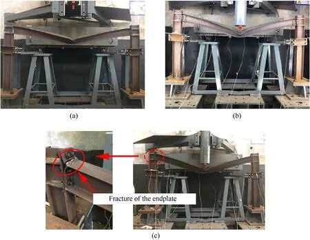
Fig.5.Experimental results of the three types of joints: 400 °C and 11.87 m/s: (a) WC;(b) WBC;(c) EEC.
The measured results of the frame subjected to impact in localised fire,including the vertical and lateral displacement at the mid-span of the beam and axial displacement at the column top,are shown in Table 1.The aforementioned table illustrates minimal differences in the impact resistance of the three types of joints at ambient temperature.The deflection was greatest for the EEC steel frames and least for the WC steel frames when the temperature increased to 400°C.The above-mentioned phenomena suggested that better impact resistance was provided by the WC compared with the WBC,and EEC was the worst at elevated temperatures.This phenomenon was significantly intensified with the increase in temperature.
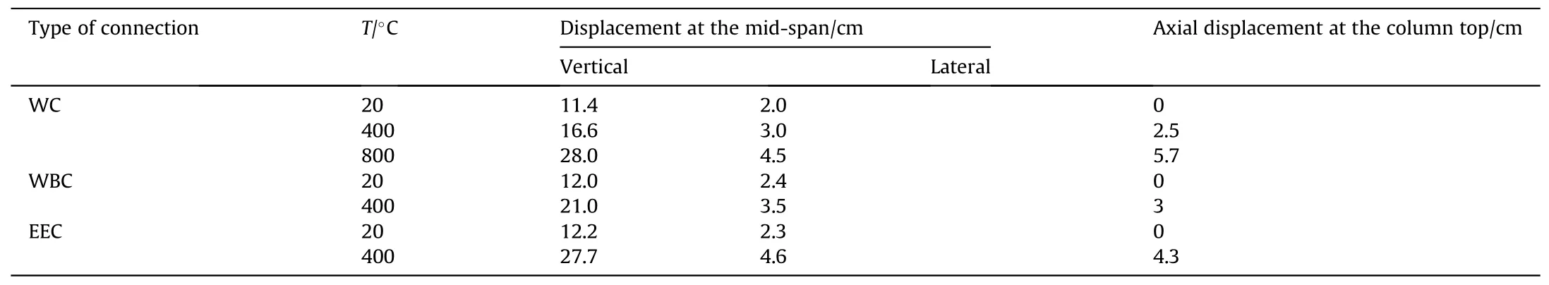
Table 1 Measurement results of the experiment.
3.FE model
The experimental behaviour of the above-mentioned structure can be reproduced to test the validity of the numerical results using ABAQUS for numerical simulation.Further parameter analysis can be carried out to comprehensively and extensively investigate the structural response and connection performance.
3.1.Structural models and analytical steps
Given the structural symmetry,semi-structured methods can be employed to effectively improve computational efficiency.In the numerical simulation,the drop hammer was replaced by a Mass.The Mass was 68.5 kg,and its velocity is 11.87 m/s before the impact.In this study,the SDR was in the range of 8-32,and the temperature was in the range of 20-800°C to investigate the effects of SDR and temperature on the impact response of the structure.The data of the main models are shown in Table 2.
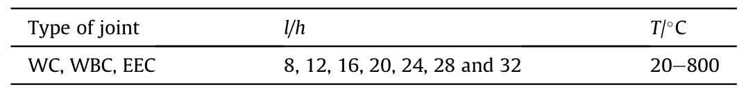
Table 2 Part of the model conditions.
During the impact,different parts of the frame components came into contact with each other.The different types of contact must be reasonably simplified and simulated.“Tie” contact was used to set the position connected together by welding [18].Surface-to-surface contact was applied in the other parts of the specimen to ensure the correctness of the contact and continuation of the subsequent calculations.The master and slave faces of each interface pairs must be manually searched to guarantee that no penetration will occur between the meshes.The tangential and normal behaviours of contact were accounted for in the contact properties.Penalty friction formulation was selected for the tangential behaviours of contact,and its value was set to 0.3[14,16].The nonlinear penalty method was used in Fig.6 to improve the convergence of the calculation and solver stability for the normal contact behaviours.The value of Kewas the representative underlying element stiffness.The heating effect of the heating box on the surface of the frame beam is simulated by radiation and convection,and the temperature field distribution in the steel beam is determined by heat conduction,as shown in Fig.7.The radiation factor,convection coefficient,and thermophysical parameters should be defined.According to the EC1[28],the convection coefficient of the directly heated surface for the frame beams was given as 9 W/m2°C,whilst the other areas were taken as 4 W/m2°C.The radiation factor of the directly heated surface for the frame beams was set to 1.0,whilst the other areas were taken as 0.8.
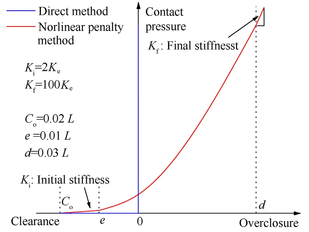
Fig.6.Nonlinear penalty pressure-overclosure relationship curve.

Fig.7.Schematic of the method of thermal transfer.
The coupled temperature-displacement static and dynamic analysis modules were adopted,and the calculation process was carried out as follows:
(a) Buckling analysis was conducted to obtain the buckling mode and the initial geometric imperfection of the beam to predict the possible out of plane behaviour of the structure According to EC3 [29],the amplitude of the geometric imperfection was 1/150 of the deformation value in the first mode.
(b) Static analysis was carried out to introduce gravity on the whole structure and application of the bolt load [30,31].
(c) Heat transfer analysis of the steel frame was conducted,which was raised to the specified temperature in accordance with the ISO-834 standard fire curve.
(d) Impact dynamic analyses were performed.
3.2.Elemental types
Components,such as beams,columns and endplates,including bolts,were modelled using solid elements(C3D8RT that considers the temperature degrees of freedom).Mass adopts discrete rigid shell element (R3D4).All components have been meshed utilised the structured meshing technique,except for bolts and mass block,which are meshed using the free meshing technique.Fig.8 shows an overall view of the 3D detailed FE model of an assembly by using the WBC and EEC.

Fig.8.FE models of WBC and EEC.
3.3.Constitutive model with temperature and strain rate effect
The full process of the material from elasticity,plasticity to damage failure,as well as the corresponding strain rate and temperature effects,needs to be accounted for to achieve refinement in the numerical simulation.The material model is shown in Fig.9.The engineering stress-strain curve can be obtained through the uniaxial tensile test of the material.The classical metal plasticity model in ABAQUS was used to simulate the nonlinear behaviour of the materials.The material properties in the model should be defined by the true stress-strain relationship instead of the engineering stress-strain relationship.The main indexes of members other than bolts are as follows: Young's modulus is 206 GPa,the yield stress is 290 MPa,and the ultimate tensile stress is 430 MPa.Meanwhile,the Young's modulus and yield stress of the bolts are 210 GPa and 640 MPa.

Fig.9.Stress-strain curve.
The structural steel materials have two damage modes,namely,ductile failure and shear failure(D-S).The initial equivalent plastic strain is related to stress triaxiality.Relevant established studies have concluded that the smaller two initial equivalent plastic strains can be applied [17] and calculated by using Eq.(1) and Eq.(2):
DUCTCRT and SHRCRT have been defined as the ductile and shear damage initiation criteria,respectively.The corresponding damage factors according to Eq.(3)and Eq.(4)[30]are employed to characterise the development degree of the material from the yield to the damage initial point,as shown in the (b) and (c) stages of Fig.9.
The reduction in material stiffness after the onset of damage was characterised using the stiffness reduction rate SDEG (i.e.“D” in Fig.9).When SDEG >0 was satisfied,material damage started to occur,and when SDEG=1 was satisfied,damage to the material completely and macroscopically manifests as fracture failure and ultimate strength,as recommended by EC3 (Table 3).

Table 3 Reduction of the material properties by the effect of temperature.
whereTis the current temperature,Tmis the melting temperature,andTtis the transition temperature defined as the one at or below which there is no temperature dependence of the yield stress.
With regard to the temperature effect,the reduction factors of Young's modulus and yield strength was adopted.The Cowper-Symonds equation was used to account for the strain rate effect,where the relevant parameters are taken as follows:C=40.4 andP=5 atT=20°C[32];C=400 andP=1 atT=1000°C[23,33].However,accurate data about temperature-related parametersCandPare lacking in the literature,and linear interpolation method has been widely accepted.In this study,the values are taken by linear interpolation when the temperature is between 20°C and 1000°C [27].The effect of temperature and strain rate on the damage initiation equivalent plastic strain of Q235B has been investigated in previous studies [34].The initiation equivalent plastic strain was amplified or reduced by introducing influencing factors related to the strain rate and temperature,defined as ICSR and ICT,respectively (Fig.10).ParameterT*in Fig.10 is related to the material properties and temperature,and it is calculated by using Eq.(6).The effect of temperature and strain rate on the density ρ and Poisson's ratio ν of the materials was neglected,where ρ is taken as 7850 kg/m3and ν as 0.3.
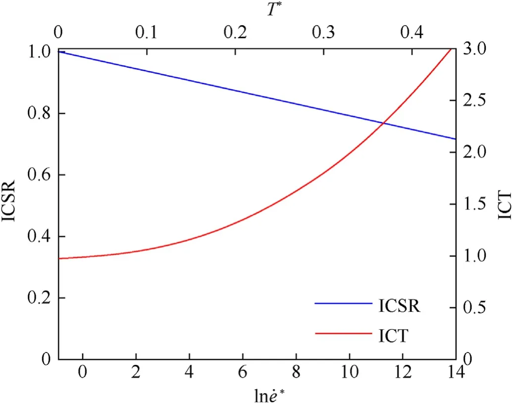
Fig.10.Strain rate and temperature effects on
The recommended values of expansion coefficient,conductivity and specific heat capacity with temperature in EC3 were adopted for the thermophysical parameters [29].
3.4.Mesh sensitivity study
The influence of element size on hourglass energy and deformation mode should be considered to improve the accuracy of the FE results.Fig.11 presents the curves of the element sensitivity results,and Fig.12 shows the mid-span deformation of the beam,where ALLAE is the total artificial strain energy;and ALLIE is the total strain energy.Deformation and energy stability were used as criteria to assess the accuracy of the model.No local buckling occurred at the mid-span when the element size is less than 3.5 mm.Based on energy and deformation stability analysis,the element size of beam and joints is 2.5 mm,and that of column is 3.5 mm.Therefore,the number of elements with different joint types and SDR for the FE models can be determined (Table 4).

Table 4 The number of element.

Fig.11.Strain energy and deformation curves with different element sizes.

Fig.12.Deformation comparison with different element sizes.
4.Numerical results
4.1.Comparison with the experimental results
The mid-span displacement of the frame beam obtained by experimental and numerical simulation is shown in Table 5.The comparative analysis shows that the error between the results is small.Hence,the effectiveness of the calculation model is verified.
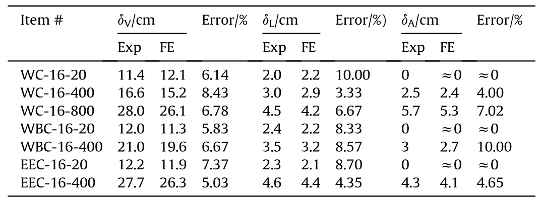
Table 5 Comparison of the experimental (Exp) and FE results of deformation.
The typical results of deformation comparison between the experiment and the FE are shown in Fig.13.The basic trend and size of deformation are consistent.In the WC-16-800,the buckling produced by the web at the impacted position of the beam is consistent with the FE results.In the EEC-16-400,a significant shear fracture occurred between the first and the second rows of bolts in the endplate during the experiment.Fig.13(c)-Fig.13(e) show a comparison of the structural transient deformation captured with a high-speed camera with the numerical simulation results.In terms of both time course and deformation trends,both results for the several typical joints are basically consistent.The comparison results show that the same torsional-flexural buckling characteristics(including direction,amplitude and moment)are developed at the mid-span.In summary,the experimental behaviour can be accurately simulated by using a material constitutive model considering damage evolution.

Fig.13.Comparison of the deformations from the experiment and FE models:(a)EEC-16-400;(b) WC-16-800;(c) WC-16-400;(d) EEC-16-400;(e) WBC-16-400.
4.2.Connection failure modes
In this section,ductile damage and shear damage are used to analyse the failure mode of joints.Fig.14 depicts the contours of damage for three joint types at 400°C.
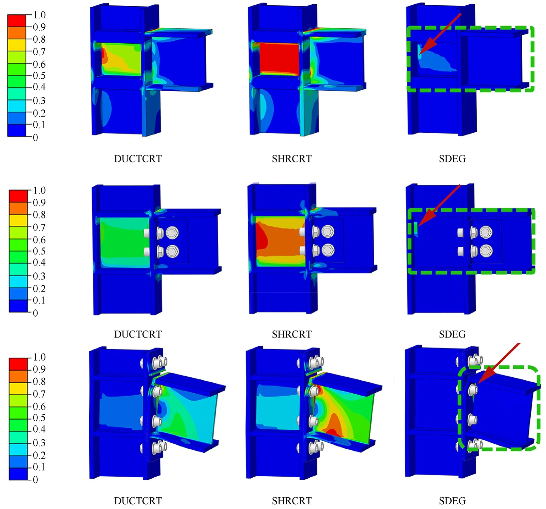
Fig.14.Contours of damage for three joint types.
The damage areas of WC and WBC are mainly located in the web of the column.The ductile damage and shear damage are distributed.The damage area of EEC is mainly concentrated in the connection between the endplate and the beam,including the second row of bolt holes,and the damage type is dominated by shear damage.It is worth pointing out that the heights of the three joint damage areas are situated in the tension zone above the neutral axis of the beam.The direction of the displacement field in the plane is plotted in Fig.15.The aforementioned figure shows that EEC presents a state of unidirectional tension,whilst the WC and WBC demonstrate the state of upper tension and lower compression.In terms of failure modes,there is a kind of cooperative failure mode among beams,columns and joints occurring in WC and WBC,defined as connection failure.The synergistic failure of the beam and endplate,defined as the end of beam failure,occurs at the EEC.This notion means that a certain load carrying capacity is still available after the failure,and the strength of the endplate plays an important role in the performance of the EEC.
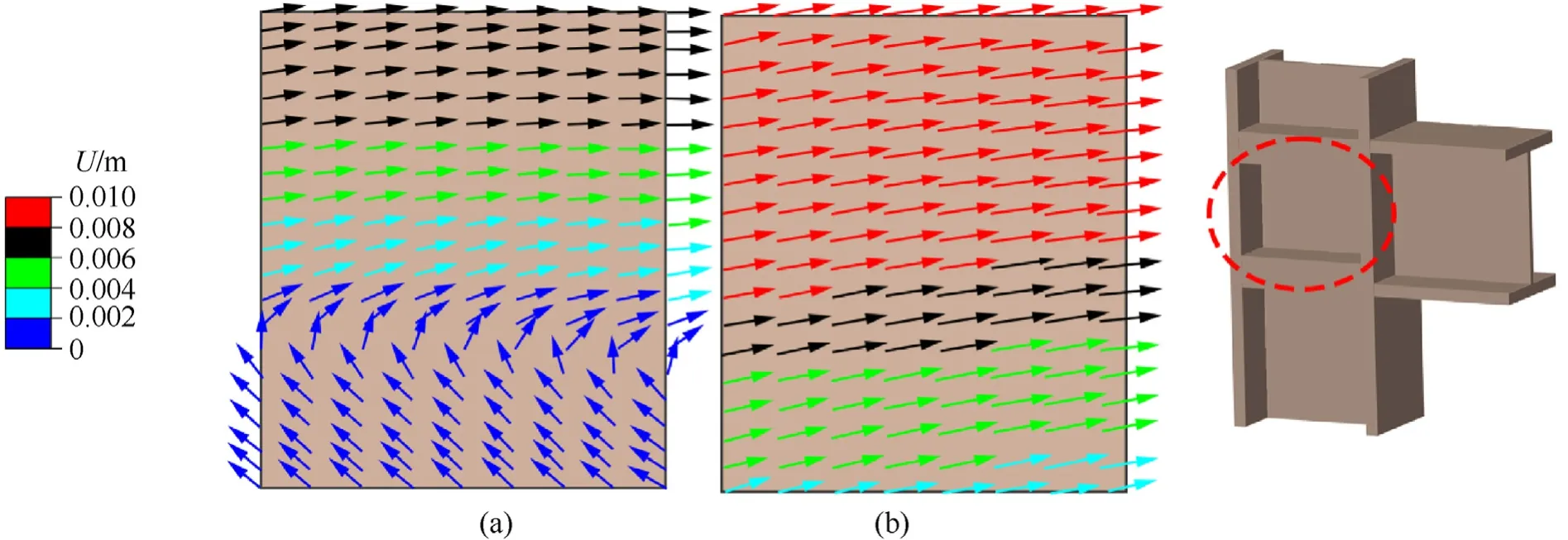
Fig.15.In plane displacement field diagrams: (a) WC and WBC;(b) EEC.
4.3.Mechanism analysis and parametric study
4.3.1.Internal forces in plane and deformations
The crossover point of the neutral axis extensions at the beam and column sections was chosen as the coupling intersection.The beam and columsn sections were linked at the crossover point to simulate the theoretical rigid connection (TRC) of the beam and column.There was a novel approach that the degree of reduction in impact resistance of the three joints steel frame in fire was assessed by comparing the internal forces of the three connections with the TRC in this section.The schematic of the TRC is shown in Fig.16.
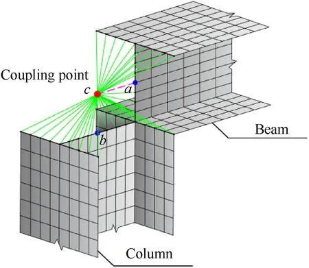
Fig.16.Schematic of the TRC.
The resisting bending moment at the connections was an important index of frame performance of the steel frames.Quantitative analyses of joint performance degradation were conducted by comparing the bending moments of the column section at the connection and bending moment degradation coefficient β defined as follows:
During the impact,the out-of-plane internal forces were far less than the in-plane internal forces even though the out-of-plane displacement occurred in the frame beam.Thus,the major focus in this section was on in-plane forces (i.e.axial force and bending moment).
The history curves of the axial force and bending moment of the beam sections at the connection are shown in Fig.17.The aforementioned figure demonstrates that the axial forces in the beam at ambient temperature were expressed as pressure throughout the impact.The axial force exhibited pressure first with the increase in temperature.Then,the axial force gradually decreased to transform into tension during the impact.It was worth noting that this phenomenon in which the direction of the axial force changed intensified with the increase in temperature.Meanwhile,the peak and duration of pressure tended to decrease.

Fig.17.History curves of the axial force and bending moment.
In addition,the temperature significantly affected the bending moment at the connection of beam section,and a negative correlation between temperature and bending moment was shown.The“compression arch action (beam action)” was confirmed by the phenomenon of axial force in the beam.An increasing axial force was observed during the impact,which was the characteristic of the “catenary action”.A clear demonstration of the internal force mechanism is shown in Fig.18.The time at which the frame beam began to be the catenary action and the duration of each phase can be easily distinguished on the basis of this criterion.

Fig.18.Internal force variation mechanisms of frame beam: (a) Compressive arch action and (b) catenary action.
The curves of the rotational angles and axial displacement at the connection with temperature for the three joints after impact loading are shown in Fig.19,where the rotational angle ψ was calculated as in Eq.(8):

Fig.19.Curves of the rotational angle and lateral displacement: (a) WC;(b) WBC and (c) EEC and (d) Curves of bending moment and β with temperature.
where ΔLA,ΔLB,ΔLCand ΔLDare the axial displacements of points A to D in Fig.2,respectively;andLCDandLABare the distances between the two points.
Fig.19 shows a positive correlation between the rotational angle and the temperature for the three joints when the temperature was within a certain range.However,the significant and varying degrees of reduction in the rotational angles of all joints suddenly occurred at a certain temperature.Then,the rotational angle slightly increased with the further increase in temperature.The three processes of rotational angle were divided into compressivebending stage (CBS),coupling compressive-bending and tensionbending stage (CCB-TBS) and tension-bending stage (TBS) based on the characteristic of the forces at the ends of the frame beams in each phase.Tcr1andTcr2were defined as critical temperatures for the aforementioned three stages.
The rotational angle of the joints was related to the internal force mechanism variation of the frame beam.During the phase of the compression arch action,a greater rotational angle was observed due to the larger bending moment at the connection.At the phase of the catenary action,a smaller rotational angle could be found because of the smaller bending moments at the connection.Nevertheless,a greater deformation occurred due to the increase in the lateral displacement at the mid-span of the beam,which did not mean that the rotational angle could be increased at the phase of the catenary action.Based on the above analysis,a more convincing explanation can be provided for the phenomenon of rotational angle changes.The frame beams were mainly in the internal force mechanism of the compression arch action during the CBS.At this moment,a decrease in stiffness and strength of the steel due to the effect of temperature resulted in a certain reduction in the bending moment at the beam end.However,the rotational angle tended to increase because the effect of increasing deflection was stronger than the decrease in bending moment.In the CCB-TBS,a significant degradation of the compression arch action was observed in the early stages of the impact,followed by a progression towards the catenary action,which made a sudden reduction in the rotational angle.The bending moment reduced to 25%at the TBS compared with the ambient temperature.At this stage of the catenary action,the tensile force at the beam end has caused an axial displacement of the column,allowing the occurrence of increased rotational angle.Fig.19 shows that the horizontal displacement at the column end was essentially the same at temperatures belowTcr1and rapidly increased when the temperature was aboveTcr1,which could also provide an explanation for the above-mentioned phenomenon.In addition,a significant tilting of the frame columns was observed,which was the hallmark characteristic of the catenary action.
WC was used as an example to analyse the relationship between the bending moment of the column sections at the connection during the impact process and the bending moment degradation coefficient β with temperature,which is shown in Fig.19(d).The maximum and average bending moments decreased with the increase in temperature,which also supported the above conclusion that the degradation of compression arch action has occurred.The main feature of the‘compression arch action’was the development of bending moments and axial force at the beam end to work in coordination with the columns.With regard to the bending moment degradation coefficient,the figure shows that the value of the WC was 0.7 at ambient temperature,which was 28% higher than that at 600°C.Accordingly,a negative correlation exists between temperature and β.The effect of temperature,so to speak,plays an important role in the performance degradation of the steel frame.
The history curves of the impact force and the curves of the peak and duration of the impact force with temperature are shown in Fig.20 and Fig.21,respectively.The comparison in Fig.21 indicated that the peak and duration of the impact force were negatively and positively correlated with temperature,respectively.In the three phases of the impact (impact,stabilisation and rebound),the increase in temperature had essentially no effect on the duration of the impact phase.However,the duration of the rebound phase had been increased due to the effect of temperature.In this section,the relationship between impact force and duration with temperature has been described.Furthermore,the lower efficiency in absorbing transient impact energy was exposed at elevated temperatures.The FE results,associated with impact forces,were expected to be in good agreement with the previous studies [35],validating the accuracy of the numerical simulation.

Fig.20.History curves of the impact force.

Fig.21.Curves of the peak and duration of impact force.
4.3.2.Energy distribution
The characteristic of energy transformation can be employed to further analyse the state of energy absorption in beams and columns during the impact and the transformation of the mechanism in the steel frames.In this section,an energy analysis was carried out for the main energy absorbing components (beams and other components) during the impact,with the WC as an example.A fundamental physical law,the Law of Conservation of Energy,applies to a confined system and is also valid for FE calculations,satisfying Eq.(9) and Eq.(10).
whereEFD,EKandETare total energy dissipated through frictional effects,total kinetic energy and total system energy,respectively;andEI,ESandEPare the total strain energy,the total elastic strain energy and the total plastic strain energy,respectively.In this study,PEbandPEcwere defined as the total plastic strain energy of the beams and columns,respectively.
Fig.22 shows the normalized histogram about the ratio of the value ofPEbandPEcas a percentage ofET,in which the red and blue colors represent beams and other components,respectively.The figure demonstrates thatPEbtended slowly decrease at temperatures belowTcr1(basically in the range of 0.7-0.8).However,a sudden rising trend ofPEbwas observed at temperatures aboveTcr1,which ranged from 0.8 to 0.9.The conclusions obtained in the previous section regarding the transformation of the mechanisms can be adopted to explain the above-mentioned phenomenon.In the CCB-TBS,less axial forces and bending moments are exerted on the column end because of the initial development of ‘catenary action’ when the temperature varies fromTcr1toTcr2,allowing the column to be less involved in energy absorption.The above analysis can be taken as an explanation for the increase ofPEb.When the temperature was aboveTcr2,the one step further development of the catenary action made it evident that axial tension forces increased.However,the bending moment continued to decrease,resulting in an increase in PEcsince the tipping of columns.
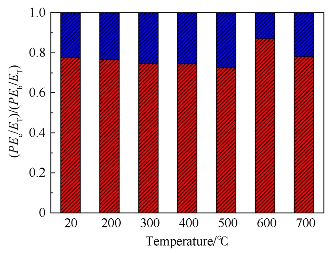
Fig.22.Normalized histogram of (PEc/ET)/(PEb/ET).
An energy-time analysis of the frame columns was carried out to further investigate the energy distribution of the steel frame during impact.The time curves ofPEc/ETare shown in Fig.23.Due to the transformation of response mechanism,the energy dissipation under the influence of temperature is not monotonic.The figure demonstrates that a significant variation in the energy absorption process of the column occurred,especially when the temperature was higher thanTcr1.A hysteresis phenomenon about the development of plastic was also observed in the column.The higher the temperature was,the longer the duration of hysteresis,and the hysteresis phenomenon disappeared at the temperature belowTcr1.The reasons for the above phenomenon can be explained as follows.First,less axial forces and bending moments were exerted on the columns at the beginning of the impact in the small-deformation stage,leaving the frame columns uninvolved in the energy absorption.When entering the large-deformation phase,a gradually increasing axial tension was applied to the column end,causing the frame columns to begin to engage in the overall energy absorption at this time.The explanations also resulted in a time delay for the frame column to be involved in energy absorption.The hysteresis phenomenon has been allowed to be exposed in combination with the above-mentioned explanations.Moreover,the hysteresis phenomenon was a characteristic of the development for catenary action.

Fig.23.History curves of PEc/ET.
4.3.3.Effects of temperature and SDR
In this section,the impact response of the steel frames under the influence of temperature and SDR would be investigated for three different connection forms,namely,WC,WBC and EEC.
Fig.24 shows the rotational angle,vertical displacement at the mid-span and bending moment degradation coefficient β for different connection types with diverse temperatures and SDR.In terms of the size of the rotational angle,the order from largest to smallest was WBC,WC and EEC.A trend of varying degrees of increase forTCR1andTCR2was observed with the increase in SDR,where theTCR1of WC was highest,and the EEC was lowest.Fig.24(c) demonstrates that the vertical displacement at the midspan of the EEC,WBC and WB decreased in turn.At ambient temperature,the difference of deflection in the mid-span beam between the three connections was narrow when the SDR was small.A widening difference emerged with the increase in temperature and SDR.This phenomenon indicated that the SDR exhibited a stronger influence on deflection than temperature.

Fig.24.Parametric analyses based on the connection type,temperature and SDR: (a) and (b) Influence on the rotational angle;(c) Influence on the vertical displacement;(d)Influence on β.
A parametric analysis based on bending moment degradation coefficient β was carried out.The results showed a significant disparity in the performance of the steel frames with different connection types -the β of WC was the largest,and EEC was the smallest,as shown in Fig.24(d).The effect of SDR had a weak influence on β.However,a significant decreasing trend in β occurred with the increase -decline by 29%,32% and 21% at 600°C compared with the ambient temperature.At ambient temperature,the β values of the WC,WBC and EEC were approximately 0.7,0.65 and 0.5,respectively,showing that even the performance of WC fell far short of the TRC.The following comprehensive conclusions about the performance of the different connection types could be derived combined with the above-mentioned parameter analyses.For the WC steel frame,the impact resistance and synergistic operation of the beams and columns were strongest,and the EEC steel frame was the weakest.In addition,a significant difference in performance to fully rigid connection was also observed,even compared to the WC steel frame.
4.3.4.Effects of impact velocity and mass
The effects of impact velocity and mass on the mid-span displacement of the frame beams with different end constraints in high temperature environment are investigated via FE with the assumption that the impact momentum remains unchanged (set up as 500 kg m/s).
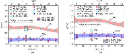
Fig.26.Dynamic displacement amplification factor in fire: (a) 400 °C;(b) 600 °C.
5.Conclusions
In this study,the dynamic behaviours and internal force mechanisms of restrained beams subjected to localised fire and sequent impact loading were systematically investigated.The following conclusions are drawn based on the experimental observations and parametric analysis by numerical simulations.
(1) The temperature effect has an important influence on the deformation of the restrained beams.Only a certain degree of local buckling occurred at the mid-span section for the three connection types of restrained beams at 20°C.The endplates of extended endplate connection were sheared off at 400°C,which could not been not observed at 20°C.Meanwhile,different degrees of torsional-flexural buckling were observed at the mid-span section at 400°C.When the temperature was up to 800°C,distortionary buckling was evident at the mid-span,and the load-carrying capacity was almost completely lost.
(2) At elevated temperature,two different failure modes were observed in the joints,namely,the connection failure and the beam end failure.The failure modes of the welded connection and welded-bolted connection were first damaged at the junction of the web and the outer flange of the structural column,which belonged to “the connection failure”.The extended endplate connection was first damaged at the connection between the endplate and the upper flange of the beam,which belonged to“the beam end failure”.
(3) At elevated temperature,the welded connection and welded-bolted connection frame columns would suffer a greater degree of damage and have lower residual load capacity due to the different failure modes.The extended endplate connection steel frames retained the structural stiffness of each floor in multi-storey frames because part of the load-bearing capacity was retained,which allowing the overall structure to be damaged but not collapsed and avoiding the progressive collapse.
(4) Different phases of force interaction were observed in the restrained beams with increasing temperature.In addition,critical temperatures (TCR1andTCR2) of the three stages existed.During the impact,the internal force mechanism included “compression arch action” and “catenary action”.The temperatures effect had driven the development of the internal force mechanism from the compression arch action to the catenary action.
(5) The effect of temperature on the dynamic displacement amplification factor is not negligible compared to the parameters of the impulsive.The values of the dynamic displacement amplification factor in high-temperature environment have been proposed for the different joints,temperatures and SDRs.
The adopted structure may not conform to the reasonable scale proportion due to the limitation of experimental conditions.The large deformation and failure of the structure may not be observed due to the small impact mass and kinetic energy.All these deficiencies need to be improved by further experimental research in the future.
Declaration of competing interest
The authors declare that they have no known competing financial interests or personal relationships that could have appeared to influence the work reported in this paper.
Acknowledgements
This work was supported by the National natural Science Foundation of China [grant numbers 12172198,11272189and 52078283];Youth Innovation Technology Project of Higher School in Shandong Province [grant number 2019KJG015].

- Defence Technology的其它文章
- Structural design of the fluted shaped charge liner using multi-section optimization method
- An aerial ammunition ad hoc network collaborative localizationalgorithm based on relative ranging and velocity measurement in a highly-dynamic topographic structure
- Molecular simulation study of the stabilization process of NEPE propellant
- Damage assessment of aircraft wing subjected to blast wave with finite element method and artificial neural network tool
- Experimental and numerical studies of titanium foil/steel explosively welded clad plate
- Thermal and ignition properties of hexanitrostilbene (HNS)microspheres prepared by droplet microfluidics