Experimental and numerical studies of titanium foil/steel explosively welded clad plate
Zhi-xiong Bi ,Xue-jio Li ,Ke Yng ,Rong Ki ,Qun Wng ,Meng-en Xu ,Ting-zho Zhng ,Xin-de Di ,Jing-ye Qin ,Yong Wu
a School of Civil Engineering, Anhui University of Science and Technology, Huainan, Anhui, 232001, PR China
b School of Chemical Engineering, Anhui University of Science and Technology, Huainan, Anhui, 232001, PR China
cSchool of Mining Engineering, Anhui University of Science and Technology, Huainan, Anhui, 232001, PR China
Keywords:Explosive welding Pressure transfer layer Titanium foil Simulation Bonding property
ABSTRACT Ti/Fe clad plate had attracted extensive attention because of its important application.In order to reduce the titanium layer thickness,the explosive welding of TA1 titanium foil to Q235 steel plate was carried out.The interfacial bonding performance was analyzed by micromorphology analysis and mechanical property test,and the formation process of interfacial wave and molten block in the vortex was simulated by smoothed particle hydrodynamics (SPH) method.The results showed that salt as pressure transfer layer used in explosive welding could play a good buffer effect on the collision between flyer and base layers.Regular waveforms were formed on the bonding interface,and the titanium foil/steel clad plate exhibited good welding quality and bonding property.The crest of the observed interfacial wave moved 200 μm from the beginning to the final formation,and it was important of jet on the formation of interfacial waveform.The interface was mainly bonded in the form of molten layer,and the grains near the interface were streamlined.Molten block containing intermetallic compounds and metal oxides appeared in the vortex of wave crest.
1.Introduction
Titanium could rapidly form a stable oxidizing protective film in air or solution[1-4].Ti/Fe clad plate has both corrosion resistances of titanium and toughness of steel,which has great utilization potentiality in chemical equipment,power generation assembly and ocean engineering [5-7].Explosive welding is an important processing method for Ti/Fe clad plate,which converts chemical energy released by explosive detonation into kinetic energy of flyer layer to achieve metallurgical bonding between the two metallic plates [8-11].Flyer layer for explosive welding needs to collide with base layer at high speed,thus the thickness of flyer layer is generally more than 2 mm to withstand explosion load [12-15].However,titanium layer with a thickness of 400 nm could play a corrosion resistance effect [1,2,16].
Due to the excellent bonding ability and corrosion resistance,it has drawn increasing interest in the explosive welding of titanium to steel.In Ning et al.'s work,Zr/Ti/Fe clad plate was fabricated by explosive welding,and their microstructure and mechanical properties were studied.The corrosion resistance of zirconium and titanium in the trilaminar clad plate was complementary[14].Song et al.[7] explored the microstructure of explosive cladding joints formed among parallel titanium and steel plates and found the bonding interface formed pronounced hierarchical microstructures.Somasundaram et al.[15] investigated the interfacial structure and corrosion resistance of TA1/304L clad plate by changing mass ratio and preset angle.The microstructural study revealed the transformation from straight to wavy interface while increasing loading ratios,and the clad plate has superior performance in corrosion environment because of the formation of titanium oxide layer.In Chu et al.’s study[12],low carbon steel and pure titanium were welded by explosive welding,and intermetallic compounds of Fe2Ti and FeTi were found at the bonding interface.Zhou et al.[6]investigated the tensile shear failure mechanism and mechanical properties of TA2/Q235 clad plate.The tensile shear failure mainly occurred along the interfacial wave direction and was caused by the defects of cavities,cracks and brittle intermetallic compounds.
The cladding thickness of clad plate might only need a few hundred microns to meet the performance requirements.Many attempts had been made to realize explosive welding of metallic foil,and the bonding properties and interfacial formation mechanism of clad plates were investigated by numerical simulation,mechanical property testing and microstructure analysis.In Yang et al.’s study[11],aluminum plate as a protective layer was placed between explosive and tantalum foil,and the tantalum foil was successfully welded to steel plate by improving traditional explosive welding technology.The microstructures of welded joints were analyzed by scanning electron microscope (SEM) and energy disperse spectroscopy (EDS),and the corrosion resistance of Ta/Fe clad plate was investigated by corrosion test.Inao et al.[17] reported that the explosive welding of aluminum foil to magnesium alloy plate was successfully realized by adding gel material as pressure transfer layer to the surface of aluminum foil,and the attenuation effect of gel material on collision energy was studied.Yang et al.[18] explored a double-layer structure consisted of a cardboard and a thin aluminum plate as a buffer layer to reduce the surface ablation and stress wave damage of copper foil/steel explosive welding.The interface evolutions,nanomechanical properties and relevant governing mechanisms of copper foil/steel welding system were investigated by SPH simulation method and advanced characterization.In Liu’s work[19],the metallic glass foil was attached on a driver plate,and an aluminum plate was coated by a Fe-based metallic glass foil.The explosive welding process was simulated by a self-developed code and the bonding mechanism was studied by numerical analysis.The buffer materials used above were inevitably damaged under the explosion load and could not be reused.
In this work,the explosive welding of titanium foil to steel plate was studied by using low detonation velocity emulsion explosive as welding charge and salt as pressure transfer layer.Microstructure evolution of the welding interface was characterized by optical microscope(OM),scanning electron microscope(SEM)and energy disperse spectroscopy (EDS).The mechanical property was measured by tensile and bending tests.The explosive welding process was simulated by smoothed particle hydrodynamics(SPH)method.
2.Materials and models
2.1.Experimental procedure
A TA1 titanium plate with a dimension of 200 μm × 100 mm × 200 mm was bonded to a Q235 steel with a dimension of 15 × 100 × 200 mm3.The chemical composition of participant metals is given in Table 1.

Table 1 Chemical composition of TA1 titanium and Q235 steel.(mass fraction%).
Based on emulsion matrix(Table 2),hollow glass microspheres were used as sensitizer and diluent to prepare low detonation velocity emulsion explosive with 20% microsphere content,whose density was 685 kg/m3and detonation velocity was 3148 m/s.Aluminum honeycomb plate was used as explosive frame,which had good compressive resistance and could ensure uniform charge thickness.Honeycomb structure explosive with a thickness of12 mm was prepared by filling honeycomb pores with the emulsion explosive,specific parameters of aluminum honeycomb panel could be found in previous work[20].A 5 mm thick salt layer was placed on the surface of flyer plate as pressure transfer layer.Salt crystal was liquefied under the high temperature of 1079 K,which could protect titanium foil from high temperature burn and reduce impact load damage [21,22].

Table 2 Emulsion matrix component.(mass fraction%).
A parallel structure was employed to the explosive welding assembly,as shown in Fig.1.The stand-off distance between base and flyer layers was 4 mm.The inner surfaces of the titanium foil and steel plate were polished,and the welding assembly was placed on the foundation of spherical tank.The initiating end was located on the left part of the charge.

Fig.1.Assembly drawing of explosive welding of TA1 titanium to Q235 steel.
After explosive welding,the specimens for microscopic morphology analysis were cut parallel to the direction of detonation by wire cutting machine.The position of the specimen was 100 mm away from the initiation end,which can avoid unstable detonation effect of the explosive in the initiation end.The general morphology was checked via OM(Carl Zeiss Axio Imager A1m)and SEM (Phenom ProX).The mechanical properties were tested by universal testing machine (MTS 810).
2.2.Explosive welding simulation
2.2.1.Collision velocity
A 2D planar model was developed in ANSYS/AUTODYN code for the explosive welding of TA1 titanium foil to Q235 steel plate.The SPH processor exhibited advantages in accurately simulating the deformation behavior of materials [23,24].The parameters of emulsion explosive and salt in the simulation were consistent with those in the experiment.To obtain the collision velocity between flyer and base plates,2D simulation based on ANSYS/AUTODYN code was carried out.The flyer material was TA1 titanium with a thickness of 200 μm,and the base material was Q235 steel with a thickness of 15 mm.The stand-off distance between base and flyer layers was 4 mm.A gauges point was set on the inner surface of flyer layer every 3 mm,as shown in Fig.2.The particle size was 0.1 × 0.1 mm2,and there were 96,600 particles in the model.

Fig.2.Assembly drawing of explosive welding.
Jones-Wilkins-Lee (JWL) equation of state (EOS) was used for the explosive,and its calculation formula was as follows [25]:
wherePis the detonation product pressure,AJ,BJ,R1,R2and ω are the material coefficients,E0is the initial specific internal energy,and V0is the relative specific volume of detonation gas products.The state parameters of the emulsion explosive are listed in Table 3.

Table 3 Jones-Wilkins-Lee equation of state parameters of explosive.
Pressure transfer layer was modelled using Compaction equation of state and Mo Granular material model,which had better simulation effect for granular material.Compaction equation of state is often used to describe granular materials,and its calculation formula was as follows [26]:
wherePis the pressure,a,c,d,and λ are constant parameters that will be determined based on various curve fitting techniques.ρ0is the initial density of the material,ρHis the current density of the material.
The pressure transfer layer was formed by salt particles,and the density of salt particles with various sizes was different.In order to reduce the differences to achieve better simulation effect.Different initial parameters were set for Compaction equation of state and Mo Granular material model.In the work,four kinds of particles were set to form the pressure transfer layer,the initial densities salt of salt particles with the same size were shown in Table 4.

Table 4 Compaction equation of state parameters of pressure transfer layer.
The Mo Granular material model can be described as [27].where σY,σP,σρand F denote the total yield stress,the pressure yield stress,the density yield stress and the pressure of granular respectively.Accordingly,pressure yield stress and the density yield stress of pressure transfer layers composed of the four kinds of particles were shown in Table 5.

Table 5 Mo Granular material model parameters of pressure transfer layer.
where ρ is the material density,Γ0is the Grüneisen coefficient,c0is the volumetric sound velocity,sis the material constant,eis the inner energy,c0is the bulk sound velocity.The specific parameters of the Mie-Gruneisen equation of state of TA1 titanium and Q235 steel are shown in Table 6.

Table 6 Mie-Gruneisen equation of state parameters of TA1 titanium and Q235 steel.
Johnson-Cook material model was used as the constitutive model for Q235 steel,which could be expressed as [30,31].
where εPis the effective plastic strain;is the effective plastic strain rate;A,B,C,m and n are the correlation constants of materials,T2is the particle temperature,T* is the dimensionless temperature,Tris the reference temperature,Tmis the melting point.The specific parameters of Johnson-Cook material model of Q235 steel were shown in Table 7.

Table 7 Johnson-Cook material model parameters for Q235 steel.
Steinberg-Guinan material model was used as the constitutive model for TA1 titanium,which described the expressions of shear modulus and flow stress before material melting as [32-34].
whereYis the flow stress,μ is the shear modulus,is the equivalent plastic strain,V1is the relative volume,Y0,β1,n,μ0,b,h and T1are the given medium constants.The specific parameters of the Steinberg-Guinan material model for TA1 titanium were shown in Table 8.

Table 8 Steinberg-Guinan material model parameters for TA1 titanium.
2.2.2.Collision simulation
In order to obtain TA1/Q235 explosive welding parameters and study the formation mechanism of wavy interface,the collision velocities of 11 gauges points were obtained by explosive welding simulation,and the collision angles of the corresponding collision velocities were calculated.The formula for calculating the collision angle with parallel installation structure could be expressed as[35,36].
wherevpis the collision velocity,vcis the collision point velocity,β is the collision angle,and vdis the detonation velocity of explosive.
The critical collision velocity between dissimilar metal plates was given by the following formula [37]:
When the girl had finished she went back to find the cows, but they had gone, and though she hunted everywhere she never found them; and she had to return home and confess to her master, who scolded her bitterly, and afterwards beat her
wherevp,minis the critical velocity,vp1andvp2are the minimum collision velocity between flyer layers and between base layers,respectively,p1andp2are the collision pressure between flyer layers and between base layers,respectively,CV1andCV2are the volume sound velocities of flyer and base layers,respectively,ρ1and ρ2are the density of flyer and base layers,respectively,and σb1and σb2are the tensile strengths of flyer and base layers,respectively.
According to the fluid mechanics theory,when the collision point velocity exceeded its lower limit,the interfacial metal transformed from laminar flow to turbulent flow,resulting in a wavy bonding.For the critical collision point velocity,the formula was as follows [38]:
wherevc,minis the critical collision point velocity,Reis the Reynolds number,andH1andH2are the Vickers hardness of flyer and base plates,respectively.
Walsh et al.[39] proposed that the ultimate collision velocity between dissimilar metal plates could be expressed as
wherevp,maxis the ultimate collision velocity,CP1andCP2are the specific heat capacities of flyer and base layers,respectively,α1and α2are the thermal diffusivity of flyer and base layers,respectively,C1and C2are the sonic speed of flyer and base layers,respectively,δ1and δ2are the thickness of flyer and base layers,respectively,Tmpminis the lower melting point of flyer and base layers,tminis the shortest time for the sparse waves to reflect to the bonding interface,and N is the coefficient related to the sonic speed of material.
In explosive welding,a large enough collision angle was required for the interfacial metal to produce jet.Therefore,the formula of ultimate collision point velocity was proposed by collision angle [40].
wherevc,maxis the ultimate collision point velocity.
An oblique collision assembly was used to focus on the collision process of Ti/Fe explosive welding in the simulation model,as shown in Fig.3.In order to save calculation time,the size of TA1 titanium as flyer layer was 200 μm×10 mm,and the size of Q235 steel as base layer was 0.5×10 mm2.The equation of state,material model and numerical simulation method remained unchanged.The particle size was reduced to 4 × 4 μm2,and there were 437,500 particles in the model,which could be enough to get accurate simulation results.The collision angles were calculated according to the collision velocities of the 11 gauges points,as shown in Table 9.
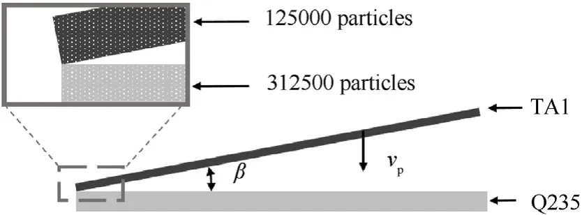
Fig.3.Schematic diagram of oblique collision model.

Table 9 Collision velocities and collision angles in the model.
3.Results and discussion
3.1.Simulation results of TA1/Q235 explosive welding
The upper limit and lower limit parameters of TA1/Q235 weldability window were calculated according to Eq.(13) to Eq.(20),as shown in Table 10.

Table 10 Weldability window parameters for TA1/Q235 explosive welding.
The critical collision velocity and limit collision velocity of the welding mode were 423 m/s and 2027 m/s,respectively,which was marked by dotted lines in Fig.4.
The collision velocities of the welding models were all higher than the critical collision velocities,which indicated that the parameters used for explosive welding of titanium foil to steel plate were reasonable [41].The starting and ending points of the explosive were affected by sparse wave,where the collision velocity was small [10].However,the detonation velocity increased and tended to be stable as the detonation transmission distance increased.
According to the parameters in Table 10,the weldability window was obtained,as shown in Fig.5.The collision velocities and collision angles of the 11 gauges points were represented by dotted lines in different colors.
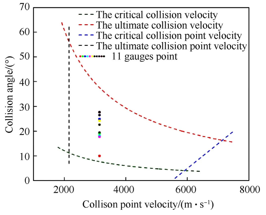
Fig.5.Weldability window of TA1/Q235 explosive welding.
It could be seen in Fig.4 that the first gauges point was located at the edge of the weldability window,and the following gauges points were in the middle of the window.The lower collision velocity at the initiating end would affect the interfacial bonding of clad plate.
3.2.Collision simulation results
TA1/Q235 explosive welding was simulated by the welding parameters of the 11 groups in Table 9,and the results were shown in Fig.6.
The collision velocity of the first group was low,and the interface exhibited a linear bonding.From the second group to the next ten groups,as the detonation transmission distance increased,the collision velocity gradually stabilized,and the bonding interface transformed from straight to wavy.There were scattered particles in the collision zone,which were metal jets of titanium and steel.The number of titanium particles were significantly more than that of steel particles.Materials with low density were more likely to form jets,which was consistent with the results of Wang [42].Metal jet could remove oxide layer and impurities on the inner surface of base and flyer layers,which was beneficial to the bonding of the two materials.
3.3.Microscopic morphology analysis
In order to study the morphology of TA1/Q235 bonding interface,the metallographic sample was prepared by grinding and polishing the sample along the direction parallel to the detonation wave.The microstructure was observed by OM,as shown in Fig.7.
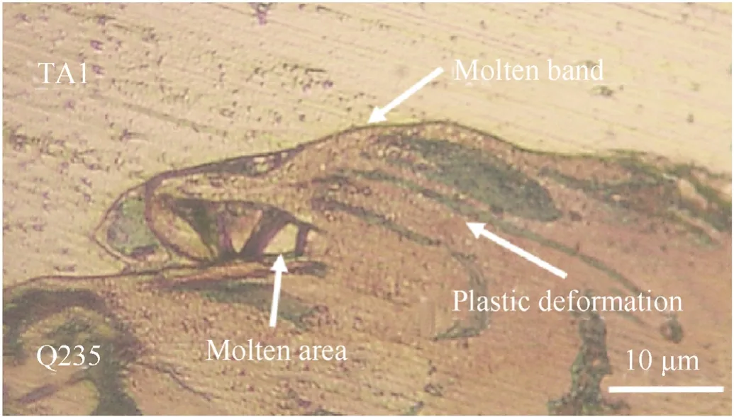
Fig.7.Metallographic structure of TA1/Q235 interface.
Fig.7 showed' the metallographic structure of TA1/Q235 clad plate.A black molten metal appeared at the interface,which was mainly bonded in the form of molten layer,and the grains near the interface were streamlined.During explosive welding,the high speed collision in a very short time caused the melting of the interfacial metal and strong plastic deformation of the grains on the steel side,resulting in rheological phenomenon and the grains on the steel side exhibited a streamline shape.The phenomenon was accordance with previous works [43-45].The interfacial air was not completely discharged in the high speed collision between base and flyer layers.Under the joint action of adiabatic compression heat and plastic deformation heat,the interfacial metals melted and diffused to form a black molten layer [44].
It could be seen in Fig.7 that the metallographic structure in the vortex of the crest contained Ti metal particles.Part of the broken particles were involved in the vortex during the movement,and finally formed molten blocks coated by base material.It was consistent with the phenomenon observed in the explosive welding by predecessors [11,46,47].
In order to further study,the components of the molten block in the vortex and molten layer at the crest,SEM observation and EDS analysis were performed,and the results were shown in Fig.8.
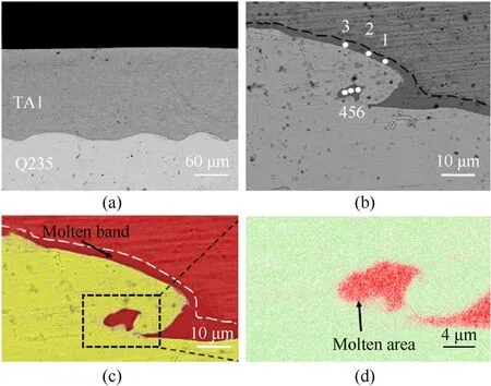
Fig.8.SEM and EDS analysis of the TA1/Q235 clad plate:(a)waveform at the interface;(b)Point scanning at the crest;(c)Map scanning at the crest;(d)Partial magnification of the molten region at the crest.
Fig.8(a) showed the back scattering diagram of the TA1/Q235 bonding interface.The average wavelength and amplitude were 100 μm and 35 μm,respectively.No holes and cracks appeared at the interface,indicating that the TA1/Q235 clad plate had good bonding quality.The average thickness of titanium layer was 170 μm,lower than its original thickness of 200 μm.Because the residual energy of the collision between base and flyer layers directly was acted on the metallic material,the residual deformation occurred in the thickness of the clad plate [19,40].Fig.8(b)displayed the local magnified scanning electron microscopy image of the wave crest.Molten layer exited on the TA1/Q235 bonding surface and the vortex of the crest contained molten block.Point scanning was conducted for points 1 to 6 in Fig.8(b)to analyze the components of molten layer and molten block,and the results were shown in Table 11.According to the point scanning element analysis of points 1 to 3,the molten layer was mainly composed of Ti element and contained a small amount of Fe and O elements.It could be seen in Table 11 that O element was detected in the molten layer,which might be because the inner surface of the metallic plate was not completely cleaned or the air between flyer and base plates was not completely expelled [5,48].According to the atom ratio of Ti to Fe,the molten block was mainly composed of intermetallic compounds of FeTi and Fe2Ti [7,10,12].

Table 11 Point scanning analysis results.
It could be observed in Fig.8(c) and (d) that the tissues on the steel side rotated,and the metallic particles in the middle form vortices,reflecting the characteristics of rotational motion during the formation of the wavy interface.It was consistent with the grain deformation of steel in the metallographic observation,indicating that the interfacial metal was in a state of high temperature and high pressure in the process of explosive welding,and the metal exhibited quasi-fluid behavior [18,19].The molten titanium and oxygen elements might form a small amount of titanium oxides,while a small amount of Fe elements diffused to the titanium layer near the interface.The molten metal cooled in a very short time,thus elemental diffusion was not obvious.
3.4.Mechanical property testing
The tensile and bending specimens were prepared following GB/T 6396-2008,which was used to characterize the bonding strength of the interface under tensile failure and the plastic deformation ability of the clad plate under bending load.The tensile and bending specimens were processed by three-point bending and tensile tests,respectively.The thickness of tensile and bending specimens was 2 mm,including 200 μm thick titanium layer and 1.8 mm thick steel layer.The specific sizes were shown in Fig.9 and Fig.10.

Fig.9.The size of tensile specimen.

Fig.10.The size of bending specimen.
The specimens were put into the three-point bending mold for bending test,and the bending specimen was observed for separation or crack to characterize its cold working bending performance.Experimental conditions and results were shown in Table 12 and Fig.11,respectively.
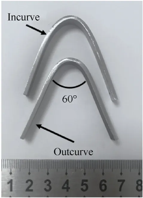
Fig.11.Physical drawing of specimen after bending.

Table 12 Conditions and results of bending test.
It could be seen from Table 12 and Fig.11 that no separation or local cracks were found at the interface of outcurve and incurve specimens,and the interface remained intact,indicating that the clad plates had good bending properties during cold working.
There might be microscopic defects at the bonding interface of the clad plate,and these defects might develop along the welding direction as crack sources under the action of external loading.The fracture morphology was observed by SEM to study interfacial morphology and bonding quality of tensile fracture specimens.The tensile failure specimen and fracture morphology were shown in Fig.12 and Fig.13,respectively.
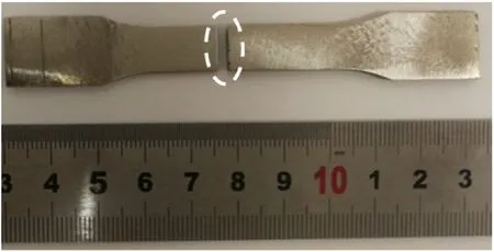
Fig.12.Physical drawing of tensile failure specimen.
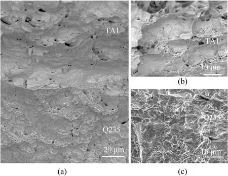
Fig.13.Fractography of tensile fracture specimen close to the interface: (a) At the interface;(b) TA1 layer;(c) Q235 layer.
Fig.13 showed the fractography of titanium foil/steel tensilefailure specimen.No separation and cracks were observed at the fracture interface,and the bonding quality of the interface was good.The tensile fracture exhibited obvious plastic deformation,and there were numerous dimples with different sizes on the fracture surface of titanium and steel layers.Compared with that of the titanium side,the dimple size on the steel side was smaller and shallower,as shown in Fig.13(b) and Fig.13(c).After high speed collision,high temperature melting and rapid cooling occurred at the interface [11].Although the process restored the toughness of the material to some extent,the possible microscopic holes in the material could be not eliminated.After nucleation,growth and aggregation of microspores under plastic deformation,these microspores were connected to each other,resulting in the ductile fracture of the material [5,48].
3.5.Formation mechanism of waveform and molten block
Explosive welding is transient and it is difficult to study the whole welding process through experiment.Bahrani-blackcrossland theory,helmholtz instability theory,vortex shedding mechanism and stress wave mechanism are the main theoretical achievements at present,among which Bahrani-black-crossland theory has a high degree of recognition.The theory takes into account the effects of collision point pressure,jet penetration and shear stress,which describes the formation of vortices and periodic waveforms vividly [18,49].
The parameters of collision velocity of 1358 m/s and collision angle of 2°were used for the collision simulation.The particles that constituted the waveform were tracked,and their velocity vectors at each stage were shown in Fig.14.The observation position was fixed and the variation of interfacial waveform was recorded every 0.01 μs,as shown in Fig.14(a).The observed interfacial wave crest moved 200 μm from the beginning to the final formation.Therefore,when the collision velocity was appropriate,the interface still needed a certain distance to form wavy bonding,which might affect the bonding morphology at the initiation point.The simulation and velocity vector diagrams of key positions of explosive welding interface were studied,as shown in Fig.14(b)-Fig.14(f).In the Bahrani-black-crossland theory,it was considered that the interface presented wavy bonding under the action of salient and re-entrant jets [49].
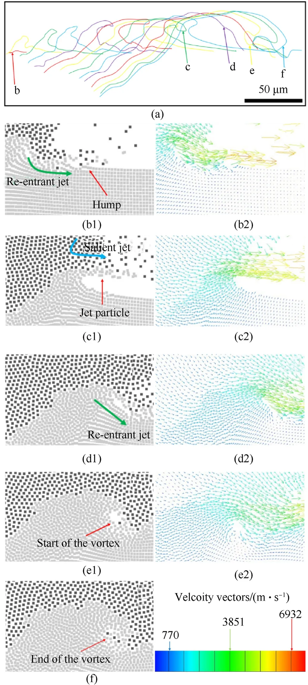
Fig.14.Collision simulation diagrams and velocity vector diagram: (a) The changing process of waveform formation,The steps of interfacial waveform formation (b1-d1)with corresponding velocity vector (b2-d2),The beginning of the vortex (e1) with corresponding velocity vector (e2),(f) The end of the vortex.
Fig.14(b1) showed the initial position of the interfacial waveform.It could be seen that the salient jet generated by the previous waveform scoured base material.The jet resulted in indentation and bump on the surface of base material,which gradually developed into a complete waveform in the subsequent evolution.The velocity of the re-entrant jet reached about 2000 m/s.The waveform formed under the action of high speed scouring and extrusion indicated the important role of jet on the formation of interfacial wave.The salient jet collided with the wave crest and formed reentrant jet in front of wave crest,as shown in Fig.14(c1) and Fig.14(d1).The direction of re-entrant jet was gradually downward,creating conditions for the formation of the next waveform(Fig.14(d1)).As the collision point moved,the particle velocity of the interfacial wave slowed down gradually.At this time,the reentrant jet was easy to form defects such as vortices and holes(Fig.14(e1)),which could affect the bonding performance[11,21,44,50].The re-entrant jet was composed of molten steel and titanium at high temperature,and the air at the interface was not discharged in time,providing an environment for Fe and Ti elements to form metal oxides and intermetallic compounds at high temperature(Fig.14(f)).
In the collision simulation study,vortex simulation diagram of TA1/Q235 explosive welding could be obtained,as shown in Fig.15(a).The molten block was composed of steel and titanium elements.This was because that steel and titanium melted in a high speed collision,resulting in mutual diffusion and the formation of intermetallic compounds.It could be seen in Fig.15(a)that the gap between particles was large,and there might be oxygen not completely expelled in time at the collision interface,resulting in the formation of metal oxides at the interface.It was similar to the component of molten block observed by SEM image in Fig.15(b).
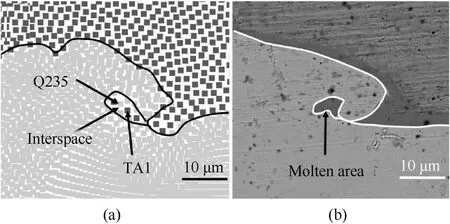
Fig.15.SEM and simulation images of vortex: (a) Simulation image of vortex;(b) SEM image of vortex.
3.6.Interfacial characteristic of TA1/Q235 explosive welding
The plastic strain,density,temperature and pressure variation rules of collision interface were obtained by numerical simulation to study the interfacial characteristic,as shown in Fig.16.
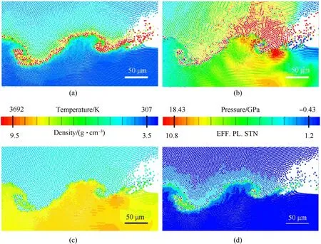
Fig.16.Interfacial characteristic diagrams of explosive welding: (a) Temperature distribution;(b) Pressure distribution;(c) Density distribution;(d) Plastic strain distribution.
Fig.16(a)-Fig.16(d)showed the temperature,pressure,density and effective plastic strain distributions of TA1/Q235 explosive welding interface,respectively.The temperature of the interface and vortex was close to 4000 K,and the interfacial pressure basically exceeded 18 GPa.As the distance from the interface increased,the temperature and pressure of base and flyer materials decreased rapidly.Both base and flyer materials melted,and intermetallic compounds were easily formed at the bonding interface [7,10,12].The molten layer at the interface was usually thin,and base and flyer materials still maintained good mechanical properties when the distance from the interface was 50 μm.The density of titanium and steel was 4.5 g/cm3and 8.0 g/cm3,respectively.However,the density of molten layer at the interface was 7.0 g/cm3,which was between that of titanium and steel.The interfacial metal melted under the action of high temperature and high pressure generated by high speed collision.The molten metal cooled in a very short time to form molten layer,and created conditions for the generation of intermetallic compounds[10,18].It was consistent with the SEM observation.The maximum effective plastic strain of the molten layer and the molten block in the vortex reaches 6.Generally,the higher the temperature was,the lower the strength of the metal was,and the pressure was sharply reduced as the distance from the interface increased [51].Therefore,the effective plastic strain value of the metal at the interface was much larger than that of materials far away from the interface.
4.Conclusions
The explosive welding of 200 μm thick titanium foil to steel plate was studied by numerical simulation and experiment.Optical microscope(OM),scanning electron microscope(SEM)and energy disperse spectroscopy (EDS) were used to observe the interfacial microscopic morphology of the TA1/Q235 clad plate.Smoothed particle hydrodynamics(SPH)simulation method code was used to study the forming mechanism of waveform and vortex,and the following conclusions could be obtained:
(1) Salt was used as a pressure transfer layer,which could decrease the acceleration process of explosive welding and avoid the high temperature burn caused by explosive detonation,and titanium foil/steel explosive welding was successfully achieved.No separation or local cracks were found at the interface of bending and tensile fracture specimens,and the interface remained intact,indicating that the clad plate exhibited good cold workability.
(2) Regular waveforms could be formed at the interface of the TA1/Q235 clad plate.The average thickness of the titanium layer was 170 μm,and the average wavelength and amplitude of the interfacial waveform were 100 μm and 35 μm,respectively.
(3) The interface of titanium foil/steel clad plate was mainly bonded in the form of molten layer.The molten layer was mainly composed of Ti element,containing a small amount of Fe element.There were molten blocks in the vortex of wave crest.According to the atomic ratio,the intermetallic compounds were mainly composed of FeTi and Fe2Ti.
(4) The re-entry jet resulted in indentation and bump on the surface of base material,which gradually developed into a complete waveform in the subsequent evolution,indicating the important role of jet on the formation of interfacial waveform.
Declaration of competing interest
The authors declare that they have no known competing financial interests or personal relationships that could have appeared to influence the work reported in this paper.
- Defence Technology的其它文章
- In-plane and out-of-plane quasi-static compression performance enhancement of 3D printed re-entrant diamond auxetic metamaterial with geometrical tuning and fiber reinforcement
- Flame behavior,shock wave,and instantaneous thermal field generated by unconfined vapor-liquid propylene oxide/air cloud detonation
- Frequency domain analysis of pre-stressed elastomeric vibration isolators
- Burning surface formation mechanism of laser-controlled 5-aminotetrazole propellant
- Blast disruption using 3D grids/perforated plates for vehicle protection
- Nonlinear tight formation control of multiple UAVs based on model predictive control

