Review:A comprehensive review of optical wireless power transfer technology
Syed Agha Hassnain MOHSAN ,Haoze QIAN ,Hussain AMJAD
1Optical Communication Laboratory,Ocean College,Zhejiang University,Zhoushan 316021,China
2School of Electronic Engineering,Beijing University of Posts and Telecommunications,Beijing 100876,China
3Satellite Communication and Networking Laboratory,Ocean College,Zhejiang University,Zhoushan 316021,China
Abstract: Ground-breaking optical wireless power transfer (OWPT) techniques have gained significant attention from both academia and industry in recent decades.Powering remote systems through laser diodes (LDs) to either operate devices or recharge batteries offers several benefits.Remote LDs can remove the burden of carrying extra batteries and can reduce mission time by removing battery swap-time and charging.Apart from its appealing benefits,laser power transfer (LPT) is still a challenging task due to its low transfer efficiency.In this paper,we discuss the necessity and feasibility of OWPT and discuss several projects,working principle,system design,and components.In addition,we show that OWPT is an essential element to supply power to Internet-of-Things (IoT) terminals.We also highlight the impacts of dynamic OWPT.We outline several OWPT techniques including optical beamforming,distributed laser charging (DLC),adaptive-DLC (ADLC),simultaneous lightwave information and power transfer (SLIPT),Thing-to-Thing (T2T) OWPT,and high intensity laser power beaming (HILPB).We also deal with laser selection,hazard analysis,and received photovoltaic (PV) cell selection for OWPT systems.Finally,we discuss a range of open challenges and counter measures.We believe that this review will be helpful in integrating research and eliminating technical uncertainties,thereby promoting progress and innovation in the development of OWPT technologies.
Key words: Wireless power transmission;Optical wireless power transfer;Distributed laser charging;Laser diode;Solar cell
1 Introduction
Wireless power transfer (WPT) is a technology in which power is transferred from a source device to a target device without using a physical link (Lu X et al.,2016).In recent years,WPT has gained sig‐nificant attention from researchers and has swiftly evolved from academia towards the market.WPT has become one of the hottest topics nowadays due to the rapidly growing ubiquity of mobile devices.Mean‐while,research on energy harvesting technology has started.A growing body of research studies is dedi‐cated to energy harvesting from radio frequency (RF) signals,including TV signals,cellular base stations,and wireless fidelity (Wi-Fi) (Lin JC,2006;Talla et al.,2015),which enables ultra-low power battery free devices.This technology is free from charging and replacing batteries,but providing high electric power is difficult (Costanzo et al.,2014).Thus,there is a need to develop and enhance existing WPT techniques.
Due to the flexibility and convenience of WPT technology,its market value is growing rapidly,al‐though the transfer efficiency of WPT is lower than that of wired technology.Designing a WPT system to charge an electronic device such as smartphone (Kim SM and Kim,2013b;Lee W and Yoon,2021) is not trivial,as it must satisfy several requirements:
1.It must be able to deliver more than 1 W power.The USB 2.0 standards permit <2.5 W power (Breton et al.,2011).
2.It must ensure the user’s safety.Safety con‐cerns are paramount in the case of high power wire‐less transmission across a room.High power acoustic and electromagnetic (EM) waves can have deleterious effects on human health (Smagowska and Pawlaczyk-
Łuszczyńska,2013).
3.It must be simple and cost-effective for suc‐cessful commercialization,and practical for deploy‐ment.It must meet form factor criteria and physical specifications,as users do not like complex and heavy‐weight systems with additional components.
WPT offers numerous advantages over wired technologies as it is much more secure,comfortable,and convenient in daily life.Another main advantage of using WPT is that it can effectively operate in those environments where WPT through a wired medium is hard,dangerous,and even impossible,such as un‐derwater applications (Lu M et al.,2018).Research‐ers have evaluated different WPT techniques and ex‐plored various applications.The currently available WPT technologies can be categorized into EM based and non-electromagnetic (non-EM) based (Costanzo et al.,2014) ones,as shown in Fig.1.Several WPT methods have been reported including capacitive WPT (Kline et al.,2011;Mostafa et al.,2017),magnetic resonance coupling (Kurs et al.,2007),inductive coupling (Ho et al.,2011),resonant inductive WPT (Li and Mi,2015,Machura and Li,2019),and opti‐cal wireless power transfer (OWPT) (Jin MHC et al.,2018) for various aerial,ground,and underwater applications.Among these different WPT techniques,the concept of OWPT (Fig.2) has become more at‐tractive (Sprangle et al.,2015;Fang et al.,2019;Kat‐suta and Miyamoto,2019b;Shahjalal et al.,2019).

Fig.1 An overview of wireless power transfer (WPT) technologies

Fig.2 Configuration of wireless power transfer (WPT) systems: (a) conventional electromagnetic (EM) induction and magnetic resonance;(b) optical wireless power transfer (OWPT) system
The transmission efficiency of non-radiative coupling based transfer technology is comparatively high,so it is widely used in household devices,such as smartphone charging pads.However,the trans‐mission distance of this technology is limited to sev‐eral meters.Inductive coupling is not applicable in some scenarios because of the associated short charg‐ing distance,whereas RF-aided transfer technology can transmit power over a longer distance.The trans‐fer efficiency of RF-based technology decreases by the square of the distance (Shinohara,2010).Some research groups have demonstrated power harvest‐ing from sources like radio frequency identification (RFID) readers (Clark et al.,2009),TV signals (Parks et al.,2014),and Wi-Fi (Luo and Chin,2021).These ambient power harvesting approaches are limited to ultra-low power applications.Although RF beamform‐ing based technology was introduced to enhance the transmission distance (Yedavalli et al.,2017),the transfer distance limitation still exists.Moreover,RF transmission causes disruptive electromagnetic inter‐ference (EMI),which affects the performance of sus‐ceptible electronic devices.EMI appears as power dis‐turbance,electrostatic discharge,and RF interference.Magnetic resonance coupling has some disadvantages including a short operational distance of up to a few meters,difficulty in tuning the resonator,and incon‐venience because of the coil weight and size in porta‐ble devices.In contrast,microwave radiation can trans‐mit power up to a few kilometers.However,it has safety considerations when RF density exposure is high,and it is hard to collimate the intended receiver.Although energy harvesting and beamforming systems based on microwave radiation have been proposed,their availability and reliability are restricted by official regulators such as the US Federal Communications Commission (FCC),due to health and safety concerns.For these reasons,RF power transfer is not suitable for practical charging of laptops,smartphones,and other mobile devices (Zeng and Zhang,2015;Zhang R et al.,2015a).Motivated by the above factors,we have focused on OWPT techniques in this study.We discuss a range of challenges,applications,and future prospects of this technology.This survey not only focuses on OWPT theory,but also provides guidelines for practical OWPT system design.
Previous studies have reported different OWPT techniques.Jin K and Zhou (2019) provided a com‐prehensive overview of laser power transfer (LPT) technology.They discussed high intensity laser power beaming (HILPB),the basic principles of laser power transmission,and suitable laser and photovoltaic (PV) cell selection.They highlighted several challenges and issues related to the implementation of LPT technol‐ogy.Soltani et al.(2021) provided a tutorial for safety analysis of laser based optical wireless communication (OWC).They investigated laser beam propagation to analyze the obtained power of different laser sources.They also presented a comprehensive framework for eye,skin,and other significant factors.Laser safety analysis with consideration of optical components like the diffuser,lens,and vertical cavity surface emitting lasers (VCSELs) was carried out.In this study,we address several OWPT techniques such as optical bea‑mforming,HILPB,distributed laser charging (DLC),adaptive distributed laser charging (ADLC),Thingto-Thing (T2T) OWPT,and simultaneous lightwave information and power transfer (SLIPT).Besides in‐troducing the OWPT theory,we provide practical guidelines for OWPT system design.We outline pre‐vious studies on OWPT and the selection of compo‐nents such as light emitting diodes (LEDs),suitable lasers,and PV cells.We have dedicated a complete section to LED based Internet-of-Things (IoT) assisted OWPT.Finally,we examine several challenges in OWPT and suggest necessary counter measures.
2 Optical wireless power transfer
In this section,we discuss the background knowl‐edge of OWPT,including OWPT working principles,system design,benefits,and some projects from the literature.
OWPT can provide a promising solution to the problem of insufficient transmission distance.OWPT is a WPT technology that considers a light source as a power transmitter.This approach can extend the trans‐fer distance using simple system components.In OWPT,a light source such as LED (Zhou YH and Miyamoto,2019b) or laser diode (LD) is used on the transmitter site for the conversion of electric power into optical power.A solar cell or PV cell (Takeda,2020;Kim SM and Won,2013) is used on the OWPT receiver site for the conversion of optical power into electric power.
Takeda (2020) demonstrated an OWPT system based on optical beamforming through white LED,but its efficiency must be improved for commercial‐ization.In contrast,laser beams can be transmitted over long distances through collimated monochro‐matic light beams (Alpert and Paschotta,2013;Kim SM and Kim,2013a;Dasgupta et al.,2018).They allow a narrow cross-sectional beam.A laser device has several benefits over other devices,including com‐pact layout,large coverage,and no interference with existing radios.Although microwave systems are used for solar powered satellites,OWPT systems have emerged as an alternative technology owing to their growing development.OWPT technology takes pre‐cedence over radiative RF-based technology.First,OWPT is able to transmit high power to a distant small aperture,as a laser beam can travel over a long distance (Jin and Zhou,2019).Second,OWPT offers longer effective transmission distances than radiative RF-based technology.The laser power decreases as an exponential function,while radiative RF-based tech‐nology decreases by the square of the distance.The attenuation coefficient of OWPT is lower than that of RF.Third,OWPT also avoids EMI to neighboring electronic devices.Fourth,OWPT systems can use a PV cell as an optical receiver.This allows a mobile de‐vice to capture power from both useful optical sources and unwanted optical sources,such as sunlight.It has the capability to automatically target with accu‐racy.It makes use of a proper communication pro‐tocol to power any mobile device.The transfer effi‐ciencies (Rhee and Kim,2016) of WPT technologies with respect to distance are shown in Fig.3.

Fig.3 Expected transfer efficiencies of wireless power transfer (WPT) technologies (Jawad et al.,2017)
Although the transfer efficiencies of the other tech‑nologies are higher than that of OWPT over short dis‐tances,it is envisaged that OWPT transfer efficiency would be higher over long distances.Several stud‐ies of OWPT have been published (Haydaroglu and Mutlu,2015;Fakidis et al.,2016;Mostafa et al.,2017;Saha et al.,2017;Ding et al.,2020).Most have demonstrated OWPT using a laser transmitter and a solar cell receiver (Kong et al.,2020;Tang et al.,2020),while some have used LED transmitters (Zhou YH and Miyamoto,2019a;Putra et al.,2020b).OWPT can be a promising choice for long distance WPT,but so far it has attracted little interest.Recently,some research groups (Kim SM and Park,2020;Putra et al.,2020a) and companies such as Wi-Charge (Man‐tese et al.,2020) have started investigating OWPT for consumer electronics.Consumer devices such as unmanned aerial drones can be recharged through LD (Jaafar and Yanikomeroglu,2021).The Swiss Federal Institute of Technology has developed labgrown diamonds (Gallo,2019),which can be used to recharge moving drones through lasers.Iyer et al.(2018) from the University of Washington,USA have introduced a smartphone charging system that uses lasers inside a room.Meanwhile,many research labo‐ratories around the world have been focusing on OWPT for far-field regions (Katsuta and Miyamoto,2018;Kim SM and Rhee,2018;Xu et al.,2020).Fig.4 illustrates different application scenarios of OWPT systems.
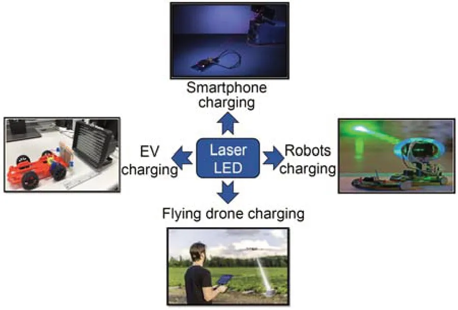
Fig.4 OWPT applications (Summerer and Purcell,2009;Boyle,2018;Carron,2018;Nguyen,2020)
In the interim,the growing research interest in marine development has increased the demand for underwater robots (Gu et al.,2020;Kim J,2020).For long-term missions using underwater robots,it would be efficient and secure to recharge batteries wirelessly (Teeneti et al.,2021).However,RF-based WPT tech‐nology is not efficient due to severe absorption in water.As visible light has relatively low absorption,visible light based OWPT can be a good choice for long-distance OWPT.Although many researchers have worked on OWPT,it is difficult to investigate OWPT that perfectly works in underwater environments.
Some researchers have been working on laserbased WPT systems,laser sources,high efficiency PV cells (Fakidis et al.,2018),and end-to-end power delivery systems (Iyer et al.,2018).Some previous studies focused on space-based solar power systems,aiming at energy harvesting for ground-based stations and power beaming for space exploration vehicles (Hoffert et al.,2004).In 2019,the US Naval Research Institute (NRI) successfully demonstrated a land-based power beaming system that used infrared (IR) laser (Jaffe et al.,2019).In 2020,the US Navy launched a power beaming satellite (Sanders and Kang,2020) into space.Laser-powered devices have been proposed for unmanned aerial vehicles (UAVs) (Nugent and Kare,2011).Also,the European Space Agency has shown interest in exploring the dark shadows of moon via laser-powered rovers (PHILIP,2019),as shown in Fig.5.Other devices have been proposed based on Fresnel lens solar concentrators for space applications (O’Neill et al.,2003) and laser-based ion engines for deep space missions (Wilson and Enoch,2000).

Fig.5 Rover testing at night (PHILIP,2019)
3 OWPT projects
3.1 OWPT projects from the literature
3.1.1 Power and data transfer over light
Philips Research Laboratories invented a tech demonstrator to transmit substantial power and data over light,considering a free space link.This technique can be used to power and read sensors and actuators over long distances without cables.This innovative technology has a higher optical quantum efficiency than IR.It provides higher data rates at low cost with relatively high power.It gives bidirectional commu‐nication with a data rate of more than 100 kb/s with native devices.Furthermore,it is possible to gain higher data rates if we use separate communication lasers.It can generate 3 V direct current (DC) to power sensors and processors without using con‐verters.In this project,researchers reported 40% opti‐cal and 12% end-to-end power transfer efficiency (Mehendale,2017).The experimental setup is pre‐sented in Fig.6.

Fig.6 Experiment for data and power transmission (Mehendale,2017)
3.1.2 Laser-powered aircraft
To increase public awareness of the potential and viability of alternative energy sources,the Na‐tional Aeronautics and Space Administration (NASA) researchers from the Marshall Space Flight Center,Dryden Flight Research Center,and the University of Alabama,USA demonstrated a ground-breaking IR laser based aircraft flight (Gibbs,2017),as shown in Fig.7.The aircraft was fitted with a 1.5 kW diode at 940 nm and an IR sensitive thin film PV array.It was outfitted with PV cells that can capture propul‐sive power from a ground based laser system to power its tiny 6 W motor.It was a lightweight radiocontrolled model airplane,designed using carbon fiber tubing and balsa wood.The aircraft body was covered by a cellophane like material,which was a ground-breaking technology for future LPT systems.Later,researchers introduced the Zephyr HALE (high altitude,long endurance) UAV,which can fly over‐night.The power beaming concept was used to en‐hance payload capacity,day/night recharging,range,flight duration,and operational flexibility.Later,the Lockheed Martin Stalker was demonstrated,which can operate continuously for 48 h.The aircraft has the ability to fly in day or night,and can track accurately under strong wind conditions.

Fig.7 Laser-powered aircraft (Gibbs,2017)
3.1.3 Autonomous rover
OWPT is also a very helpful technology for driving autonomous vehicles.Steinsiek (2003) from EADS Astrium developed ground-to-ground WPT through LDs.Researchers demonstrated this technol‐ogy using a small,completely independent rover vehicle integrated with PV cells (Fig.8).It was con‐sidered as the first step towards powering lunar sur‐face rovers and airships.The experiment was demon‐strated using a green frequency-doubled Nd:YAG laser of only a few watts,while a micro-camera was mounted on the rover as a payload for pointing and position tracking purposes for distances of up to 280 m by implementing active control loops.
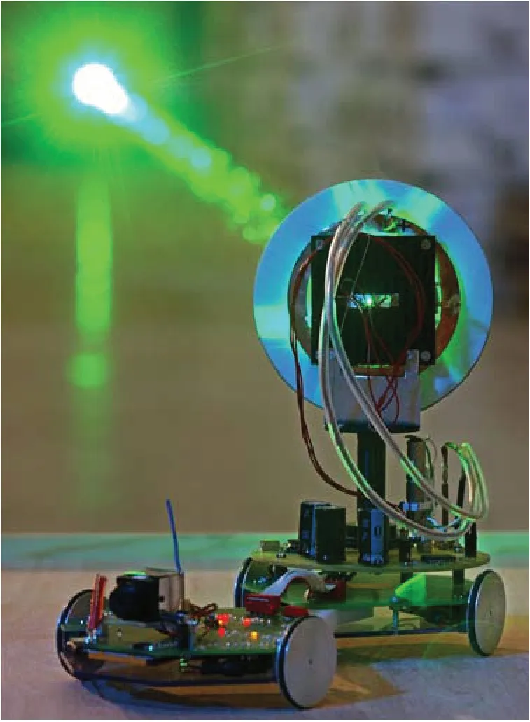
Fig.8 EADS developed laser-powered rover (Summerer and Purcell,2009)
3.1.4 OWPT for smartphone charging
OWPT can also bring us comfort and conve‐nience.Researchers from the University of Washing‐ton,USA proposed a secure novel method to charge smartphones with a laser,requiring minimal instru‐mentation to the environment.They demonstrated that a laser can be used to charge a smartphone,like a standard USB cable.They successfully delivered more than 2 W at 4.3 m for a smartphone,and at 12.2 m for a table-top form factor receiver.An invisible narrow laser beam in the IR spectrum was used for charging,while a thin power cell array was mounted on the back of smartphone.To ensure safety,they used a metal heatsink,such as aluminum strips,to dissipate excessive heat from the charging system.A retrore‐flector mechanism was used as a sensor to terminate the system if a person or object appeared in the path of the guard beam.Researchers were able to turn off the laser source at a maximum speed of 44 m/s,which reduced the exposure of human tissue to the high power laser.The heat dissipation and robust safety features may enable charging of tablets,cameras,and even computers in the future.Fig.9 shows an overview of the OWPT system developed by the University of Washington.

Fig.9 Smartphone charging system (Iyer et al.,2018)
3.1.5 OWPT system for mobile objects
Charging has always been a more difficult task for mobile objects.OWPT can be used for charging and tracking in consumer electronics.The process of charging mobile objects is called dynamic OWPT (DOWPT).This concept has been demonstrated through various experiments based on visible and in‐visible light for terrestrial and space applications.To validate the concept of DOWPT with visible light,solar energy is kept in a device containing Li-ion bat‐tery,DC-AC,and DC-DC converters.This device is used to deliver power to an LED light bulb fitted to a small electric vehicle (EV).This LED light bulb of 8 W is used as a transmitter,while a small solar panel is mounted on another EV as a receiver.The pro‐posed DOWPT system can operate at a maximum distance of 5 cm.It provides 2% efficiency at zero distance,and 1.57% at 3 cm (Nguyen,2020).For in‐visible light,a light source IR LED array of 850 nm is used,considering the same small EV.The overall reported efficiency is similar to that of the visible light experiment.This idea is illustrated in Fig.10.

Fig.10 DOWPT using invisible light (Nguyen,2020)
3.2 OWPT working principle
The basic OWPT system is based on a transmit‐ter unit (optical source) and a receiver unit (solar panel or photodiode (PD)).A high-efficiency optical source such as LD is used to convert electrical signals into a highly collimated beam,which can be transmitted over several meters with trivial losses (Kim SM and Kim,2013b;Tang and Miyamoto,2019).The solar cell re‐ceiver is used to convert optical signals into electric power.A DC circuit is used to operate the light source,while a solar cell gives a stable DC output.It is possi‐ble to achieve long-distance power transfer with a simple and compact system design.This system does not affect surrounding devices with EM noise.
A wireless transfer technique requires significant light irradiation to a solar cell from the optical source.Power transfer efficiency decreases and light is wasted when the solar cell receiver area is smaller than the light irradiated area.Moreover,the conversion effi‐ciency of the solar cell decreases.Thus,high efficiency can be maintained through an accurate irradiation beam size.Another factor that degrades the performance of an OWPT system is attenuation loss by the medium.The operation can be made unstable by weather-and time-dependent power generation (Rühle,2016).As a result,the OWPT system suffers from high losses in bad atmospheric conditions,owing to the charac‐teristics of light,which is highly absorbed and scat‐tered by aerosols in the atmosphere.Furthermore,laser light cannot penetrate rainfall and clouds.Some other critical concerns are pointing errors,blockages,mobility,and powering multiple devices.
To tackle these challenges,a beam control sys‐tem,a stable monochromatic light source,and an effi‐cient solar cell receiver are essential for an OWPT system (Kim SM and Won,2013).A monochromatic light source such as LD is suitable for OWPT sys‐tems to obtain high conversion efficiency in the solar cell receiver.A DC-DC circuit can operate efficiently with a few volts of output from a solar cell (Katsuta and Miyamoto,2017;Xu et al.,2020).Two types of solar cells are commercially available: GaAs solar cells and Si solar cells (Yamaguchi,2003;Lee TD and Ebong,2017;Matsuura et al.,2021).A singlechip GaAs solar cell provides 0.9‒1.1 V output (Kim SM and Rhee,2018;Matsuura et al.,2021),while a single-chip Si solar cell provides 0.5‒0.7 V output,which is insufficient to operate a DC-DC converter circuit.To increase the output voltage,a viable solu‐tion is to use multiple chips of solar cells in series.In this way,GaAs and Si solar cells can be used in OWPT systems with a series arrangement of multiple chips.
3.3 OWPT system design
An OWPT system has the advantage of deliver‐ing high intensity power over a long distance due to a small divergence angle and the small size of the laser beam.As the laser beam is small,it must be pointed accurately at the receiver.However,an addi‐tional device is required for laser beam steering.Dif‐ferent methods are used for beam steering and target recognition.In some studies,a four-element PD was used to detect and pinpoint the position of the target (Kawashima et al.,2007).Other researchers used a retro-directive mirror for this purpose (Wang X et al.,2016;Lim et al.,2019).Nonetheless,a perfect align‐ment between transceiver components is required to use these techniques.In this scenario,power delivery to a mobile target is difficult.Recently,Putra et al.(2020a,2020b) used DOWPT for mobile objects using an IR LED marker,a web camera with OpenCV image processing software,and beam steering using a Gal‐vano mirror.Fig.11 illustrates the OWPT system de‐sign.Researchers have explored OWPT system compo‐nents and performance in different application sce‐narios,including energy-hungry missions of flying drones and powering electronic devices (Kawashima et al.,2007;Parello et al.,2014),charging underwater vehicles and sensors (Jawad et al.,2017;Putra et al.,2019),charging implantable medical devices,e.g.,a pacemaker (Murakawa et al.,1999;Goto et al.,2001),and to deliver power to satellite and moon rovers (Shi et al.,2016).

Fig.11 Basic design of an OWPT system
4 OWPT components and research contributions
In this section we introduce several studies con‐sidering OWPT system components.We also briefly compare different optical sources,such as IR LED,edge emitting laser (EEL),and VCSEL.
In OWPT,a semiconductor laser is appropriate to generate collimated light.Although EELs can be used,VCSEL (Iga,2008) are preferable.A VCSEL has potential advantages of light output by a twodimensional (2D) array,and offers scalable array size.In the last two decades,several studies have reported laser-based WPT strategies for different application scenarios.A laser-based OWPT system was first in‐troduced for solar powered satellite application (Xu et al.,2020).Steinsiek (2003) used a 532 nm solid state LD for powering a mobile rover over a distance of 30‒200 m.Steinsiek (2003) investigated the feasi‐bility of a WPT link between a transmitter and a remote receiver.Hirota et al.(2015) demonstrated an OWPT system using a 975 nm VCSEL array and common Si solar cells.They successfully achieved 33% power generation efficiency using Si solar cell.Shi et al.(2015) reported a laser-based WPT system used on airships at a transmission distance of 50‒100 m.They achieved 13.43 W peak power at 88 W input power,resulting in a transfer efficiency of 15.26%.The use of an indoor laser based WPT system with a solar cell receiver at night was presented by Fakidis et al.(2016).They carried out OWPT system analy‐sis in the absence of ambient light.Katsuta and Miya‐moto (2018) reported an OWPT system with 15% ef‐ficiency using VCSEL and a GaAs solar cell.Recent studies reported more than 65% conversion efficiency using high power LDs with 940‒980 nm wavelengths (Crump et al.,2013).The OWPT systems used in these studies were based mainly on LD,due to its key features of a narrow spectrum,low divergence,high directionality,and high power (Hecht,2001).How‑ever,lasers also have some disadvantages.According to Japan’s safety regulations for laser products,la‐sers are classified in different groups on the basis of their power level,emission duration,and wavelength (OMRON,2022).Most laser hazards involve risks to eye safety.Thus,feasible light sources other than laser are needed.On account of its sufficiently narrow spectrum,increased output power,improved effi‐ciency,and low cost,a recent high performance LED (Optiwave Systems,2022) based OWPT system can be considered as a good alternative.Zhou YH and Miyamoto (2019a) presented an LED-based OWPT system which is capable of delivering high electric power to compact IoT terminals.They obtained effi‐cient power transfer using small GaAs solar cells and high intensity IR LED,and reported 200 mW output power at a transmission distance of 100 cm,with 41.7% solar conversion efficiency and 77% opti‐cal system efficiency.
Similarly,studies have confirmed that light col‐limation through passive optical elements such as lenses provides high directivity.Also,solar panels offer special potential for power harvesting from both a dedicated laser source and sunlight.Gray (2003) reported 100 mW/cm2irradiance from sunlight under standard test conditions (STC).Green et al.(2015) reported 12.3% efficiency for an amorphous silicon (a-Si) module at STC.They also estimated the effi‐ciency of mono-crystalline silicon and multi-crystalline silicon (multi-c-Si) cells as 25.6% and 18.5%,respec‐tively.Kinsey et al.(2011) reported the efficiency of amonix compound parabolic concentrator (CPC) solar power plants using concentrator PV technology.Green et al.(2015) reported 45.7% efficiency for a multijunction cell using a concentrator.Fakidis et al.(2014) investigated the use of an OWPT system exclusively for indoor applications.They highlighted the use of an optical wireless (OW) link for energy harvesting and backhaul communication.The OW link was gen‐erated using a white LED,parabolic mirror,and Si solar panel.The harvested power was 18.3 mW and the link efficiency was 0.1%.In a follow-up study,they created an OW link using 1‒5 red LDs,a colli‐mated lens,and a multi-c-Si solar panel (Fakidis et al.,2015).The calculated harvested power was 10.4 mW and the link efficiency was 0.74%.The reduced link efficiency was explained by the low efficiency of the solar cell and LD.The low level of harvested power was attributed to mismatch losses among solar cells and low optical power.Different OWPT systems used IR LEDs,EELs,and VCSELs.The different pa‐rameters of these optical sources are compared in Table 1.Table 2 summarizes research contributions to OWPT.

Table 1 A comparison of the different parameters of optical sources
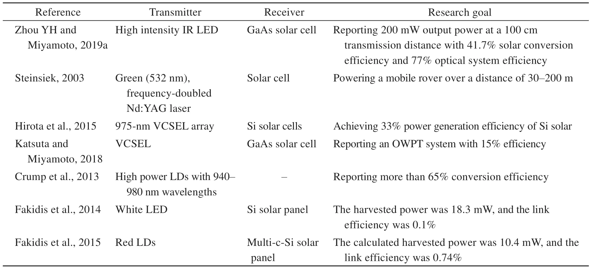
Table 2 Research contributions to OWPT
5 LED-based IoT-assisted OWPT
The information provided in this section reinfor‑ces our belief that IoT-assisted OWPT is a promising concept.We also briefly discuss the transmitter and receiver components for IoT-assisted OWPT systems.
IoT paves a way for various emerging applica‐tions in predictive maintenance,health monitoring,and smart cities.The IoT aims to connect ubiquitous devices to the Internet.Power supply is a key element to support communication and high-performance computation in IoT terminals.However,battery en‐durance is a major issue in battery-empowered IoT objects.There are two approaches for tackling this issue and increasing sustainability: improving battery charging techniques and enhancing the battery ca‐pacity.Enhancing the battery capacity can cause is‐sues such as recycling,cost,weight,and safety.In this scenario,using WPT to enhance battery endurance seems the right approach.OWPT systems can be im‐plemented in the context of wireless connectivity to IoT objects.An OWPT system designed like a porta‐ble flashlight device has been proposed in previous studies to power compact IoT terminals (Zhou YH and Miyamoto,2019a).The device is small and simple,and can be easily held by a drone,robot,or human.A small solar cell is used as a receiver,which can be put on IoT terminals.A commercially designed LED is used as the light source due to its large divergence angle,which gives high efficiency without any con‐trol system,through accurate irradiation.It is possi‐ble to target a small solar cell at a long distance (Liu WH and Feng,2017).The above discussion shows that a proper system configuration is essential to obtain a target irradiation size and specific trans‐mission distance.In previous studies,a 1-m transmis‐sion distance was achieved,which is suitable for charging various IoT terminals (Zhou YH and Miya‐moto,2021).The transmission distance can be in‐creased through proper modification of the optical system configuration or possibly considering a larger device.
5.1 Optical transmitters for IoT-assisted OWPT
The maximum conversion efficiency of a solar cell is around the spectrum limit of the bandgap en‐ergy.The numerical expression for bandgap energy is given by
whereEgis the bandgap energy,cis the velocity of light,andhis Planck’s constant.As a GaAs solar cell has a bandgap energy of 1.424 eV at 300 K (Luque et al.,2012),the related wavelength should be lower than 870 nm for IR LED.If the wavelength exceeds this value,then the quantum efficiency of solar cell will rapidly drop to zero.An IR LED with high inten‐sity is required to obtain significant electric power in IoT OWPT systems.Moreover,a small diver‐gence angle can lower the aperture of optical compo‐nents and stop optical energy leakage.A 2 mm×2 mm single-chip LED can provide a small irradiation area.In existing commercial market products,the highest intensity is 1 W for IR LEDs of 2 mm×2 mm or smaller.These LEDs have a divergence angle from a few degrees to a hundred degrees (Hecht,2001).An 810-nm (OSRAM,SFH-4703AS) IR LED with a ±40° divergence angle and 1.04 W intensity was im‐plemented in previous studies of OWPT systems.Re‐searchers successfully obtained 41.7% PV conversion efficiency.The electrical output from a GaAs solar cell was 223.9 mW and the total efficiency of the OWPT system was 6.3%.
In any OWPT system,the incident light rays are targeted on a small receiver from a long distance,requiring perfect accuracy of irradiation.To achieve high efficiency also requires a proper lens system.Researchers used a multi-lens system to achieve the divergence angle described above.The lens system combined the use of an aspheric condenser lens and a Fresnel lens.The aspheric condenser lens was used to control divergence to minimize the aperture of the Fresnel lens and optical energy leakage.The purpose of the Fresnel lens was to construct a large aperture using a small lens.Although the imaging perfor‐mance of a Fresnel lens is no better than that of a convex lens,it can be efficiently used for IoT-based OWPT applications.
5.2 Optical receivers for IoT-assisted OWPT
A solar cell is considered the best energy har‐vester in an OWPT system.Its semiconductor material is capable of converting optical energy into electric power under a PV effect.Commonly available solar cells are GaAs and Si solar cells.Although Si solar cells are cheaper,GaAs cells are preferred because of their high efficiency,based on their lightweight prop‐erties and high bandgap energy.Therefore,GaAs solar cells are usually selected,and researchers are work‐ing on their cost reduction due to their rapidly grow‐ing applications.If an LED requires a narrow spec‐trum,then a multi-junction solar cell (Yamaguchi,2003;Green et al.,2015) is not required to cover a broad range of spectrum.A low-cost single-junction GaAs solar cell matching the wavelength of an LED is appropriate to achieve high efficiency.Solar cells of 5 cm×5 cm or larger do not satisfy the require‐ments of IoT applications,and solar cells below 1 cm do not fulfill the power requirements of IoT termi‐nals,which need dozens of mW power (Nguyen and Chapman,2020).Zhou YH and Miyamoto (2019a) from Tokyo Institute of Technology,Japan demon‐strated an OWPT system for compact IoT terminals using a 1.7 cm×1.7 cm lightweight and flexible GaAs solar cell (Fig.12).
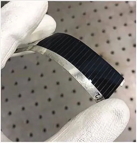
Fig.12 A thin and flexible GaAs solar cell used in an OWPT system (Zhou YH and Miyamoto,2019a)
6 OWPT techniques
The main focus of this section is to highlight dif‐ferent OWPT techniques such as optical beamforming,DLC,ADLC,and SLIPT.We also discuss research efforts dedicated to each technology.
6.1 Optical beamforming
Optical beamforming is the technique in which light from an optical source is focused on a receiver device.It enables wideband signal transmission and prevents beam-squint and imbalance loss effects.The block diagram of optical beamforming is illustrated in Fig.13.An LED or LD is used as an optical source and a solar panel is used as a receiver.A spatial light modulator (SLM) is used for LD light beamforming.An SLM is used to modulate the phase or intensity of LD light at each pixel.As an SLM can modulate light spatially in phase and amplitude,it acts as a dy‐namic diffractive module.The beam-formed light is precisely incident on the solar panel,and then optical energy is delivered from the optical source to the in‐tended object.The SLM should recognize the exact position of the intended object.A beam expander can be added to expand the laser beam size,while it can be omitted in case of an LED.Some SLM models also require a polarizer to modulate the phase of light.A Fresnel lens function controlled with a computer is used to operate an SLM as a dynamic focusing lens.After focusing the beam-formed light to the screen,optical energy is transferred to the receiver solar cell.
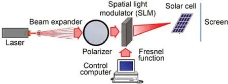
Fig.13 A block diagram of optical beamforming
Kim SM and Won (2013) proposed an optical beamforming algorithm which can automatically trace the position of an intended device.In this technique,LED-based visible light communication (VLC) and a solar cell receiver based device were used for a download communication link,while RF-based wire‐less communication,e.g.,Wi-Fi or bluetooth,was used for an uplink communication link.They also repeated their experiments using red and green LDs.Using this technology,they obtained 50%,40%,and 36% optical beamforming efficiency for green laser,red laser,and white LED,respectively.Fakharzadeh et al.(2008) demonstrated optical beamforming for targeting indoor a white LED on a receiver target.They proposed a robust,fast,and accurate algorithm to tune the coupling factors of parallel ring resona‐tors to create the target delay for optical beamform‐ing of the transmitter arrays.Recently,the US Navy made a breakthrough trialing optical beamforming for naval communications.It will test optical beam‐forming for use in challenging environments at sea.Isotropic Systems,a well-known manufacturer of broadband terminal technology,has a contract with the defense innovation unit (DIU) (Messier,2020) to design and test a new optical beamforming system (Fig.14) for reliable operation in harsh environments including intense wind,EMI,and salt water.
6.2 Distributed laser charging
During the transformation of electronic devices to wearable devices,desk phones to smart phones,and desktops to laptops or tablets,mobility has be‐come a critical challenge.IoT and mobile devices like smartphones and sensors are powered by batter‐ies with short operation times.It is difficult to charge IoT sensors installed in harsh environments,such as volcanoes and underwater environments.Carrying a power cord and finding a power socket to recharge mobile devices can be difficult and disruptive.There‐fore,a viable solution that has emerged is the wireless charging of mobile devices with the potential to re‐plenish the battery over the ether.It offers various benefits such as user convenience,product durability,usage flexibility,and on-demand availability (Lu X et al.,2015).Here,WPT appears to be a good alter‐native approach to support perpetual energy supplies.Different WPT technologies are suitable for various application scenarios,but it is still difficult to charge IoT devices including drones,laptops,smartphones,and smart sensors over a long distance.To overcome this challenge,DLC (Liu QW et al.,2016) has emer‑ged as a promising wireless charging technique.
DLC,also referred to as spatially distributed laser cavity resonance,is commercially available and has emerged as a practical light-aided charging technology.According to relevant Patent Cooperation Treaty (PCT) patents (US8525097B2 and US9225140B2) (Kim SM and Won,2013),this technology can be summarized as follows: retroreflectors are used in the receiver com‐ponent for the reflection of the incident beam from a transmitter and the detection of the transmitted optical beam path back at the transmitter.This supports the ability to adjust tunable beam parameters.The power flow due to resonance is stopped in case of unavailabi‑lity of a line-of-sight (LOS) path between transceivers.
The DLC technology offers self-alignment to charge IoT devices without any special positioning and tracking,as long as an LOS path is present be‐tween the transceivers.A small DLC receiver can be easily embedded into a sensor or smartphone or sen‐sor,and a transmitter can be attached to a ceiling.In addition,a single DLC transmitter has the capability to charge multiple devices simultaneously (Gong et al.,2013).As a DLC system uses PV cells rather than a collecting lens,it is a more practical,light‐weight,and cost-effective approach than using tradi‐tional heavy batteries.
Fig.15 shows an innovative mechanism to charge mobile electronic devices through DLC.In Figs.15a and 15b,DLC transmitter 1 with an LED array is used to design a DLC-assisted lightbulb.This DLC transmitter can be easily integrated to the wall or ceiling to charge mobile devices located in its prox‐imity.In another case,a DLC transmitter is embedded into a drone which can be used to charge IoT devic‐es such as mobile phones and tablets.A DLC receiv‐er is also integrated to the drone.Hence,DLC trans‐mitter 2 can also recharge it.Note that the efficiency of the DLC system is severely impacted by various parameters such as laser wavelength,laser transfer attenuation,and electricity-to-laser and laser-toelectricity conversion efficiency (Hu et al.,2020).Zhang QQ et al.(2018) introduced a multi-module DLC architecture and comprehensively discussed the evaluation of power conversion or transmission for each module,considering the effects of laser wave‐length,attenuation,PV cell,and temperature.Liu QW et al.(2016) briefly explained the DLC technique for safe mobile applications.They proposed two wireless charging techniques: a DLC-assisted infrastructure based network and a DLC-assisted ad-hoc network.Similarly,Wi-Charge obtained about 2 W power at a distance of 10 m to simultaneously charge several smartphones and laptops.Wang W et al.(2019) also demonstrated resonant beam charging (RBC) for IoT objects and achieved 2 W power at 2.6 m distance.Fang et al.(2019) proposed a first-access first-charge (FAFC) scheduling algorithm to enhance WPT per‐formance for multiple IoT objects by improving charg‐ing efficiency,prolonging charging time,increasing transmitted power,and restricting the number of re‐ceivers.To the best of our knowledge,several re‐search groups have explored this technology,but com‐mercial products have not yet been disclosed.Table 3 summarizes a comparison of DLC with different WPT techniques.
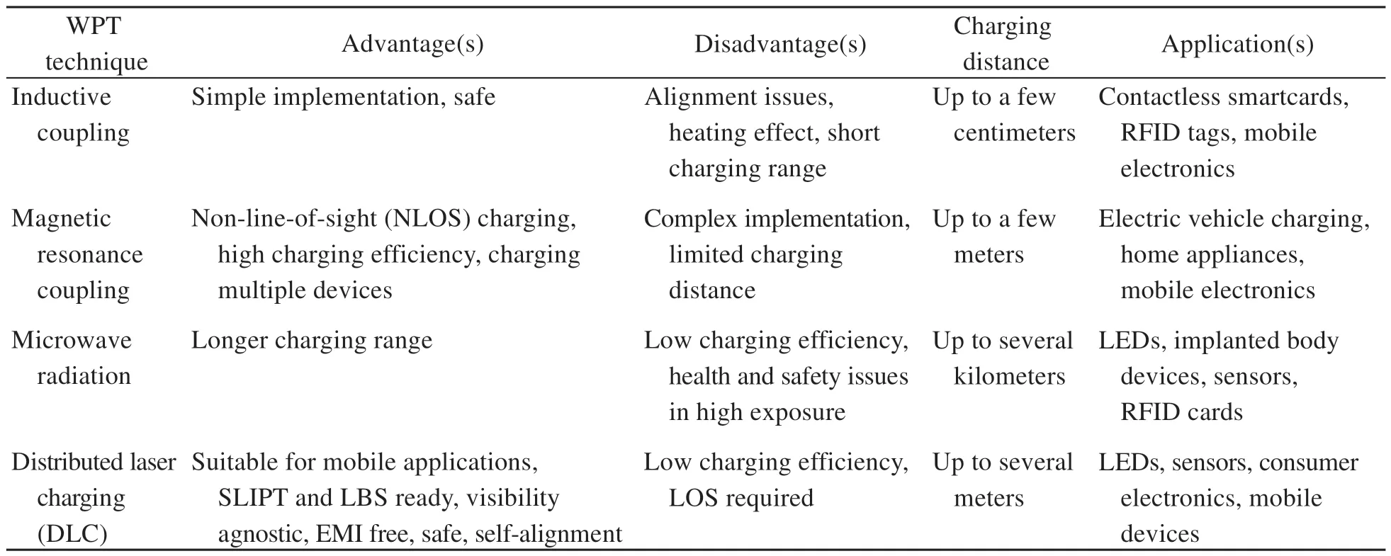
Table 3 A comparison of different WPT techniques (Liu QW et al.,2016)
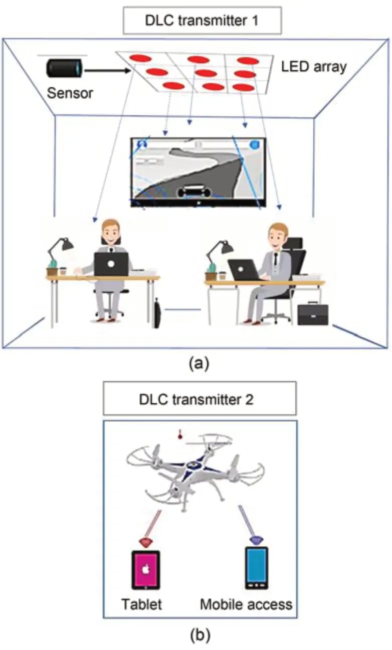
Fig.15 DLC potential applications: (a) LED array trans‐mission;(b) drone transmission
DLC provides various advantages over other LPT techniques including access control,compact layout,and a long transmission distance.However,DLC also has some potential drawbacks such as propagationattenuation,DLC receiver tracking,power conversion efficiency (PCE),laser hazard,quality-of-service (QoS),inherent LOS dependence,and DLC transmission dis‐tance under path-loss constraints.Some features (Liu QW et al.,2016) of DLC are as follows:
1.EMI-free: In DLC,there is no leakage of power outside the resonating beam.It does not im‐pose RF radiation like other WPT techniques.
2.Compact layout: In DLC,a compact receiver such as smartphone camera is used,which is suitable for the beam diameter of one millimeter.
3.Visibility agnostic: DLC can rely on visible as well as IR and ultraviolet (UV) lasers.This visibil‐ity agnostic characteristic of DLC makes it flexible and reliable for various applications.
4.Concurrent wireless charging: When a re‐ceiver comes across the LOS link of the transmitter,the DLC system creates a resonating beam.Thus,a single transmitter has the potential to generate multiple resonating beams pointed towards different receivers,which ensures concurrent charging of multiple re‐ceivers from a single transmitter.
5.Intrinsic safe: In case of a high power level up to dozens of watts,the DLC system raises safety con‐cerns.However,DLC is unique from integrated reso‐nating lasers due to the spatially distributed resonator architecture.Whenever an object appears into a reso‐nating beam path of the DLC system,the laser is cur‐tailed quickly without any extra decision-making circuit.
6.Self-aligning: In DLC,the charging process remains active until the LOS path remains between the transceiver elements.In such a situation,the distri‑buted resonator has the capability to generate a reso‐nating beam without any aiming or tracking features.
Liu QW et al.(2016) presented different fea‐tures of DLC including intrinsic safety,self-alignment,and concurrent charging (Fig.16).
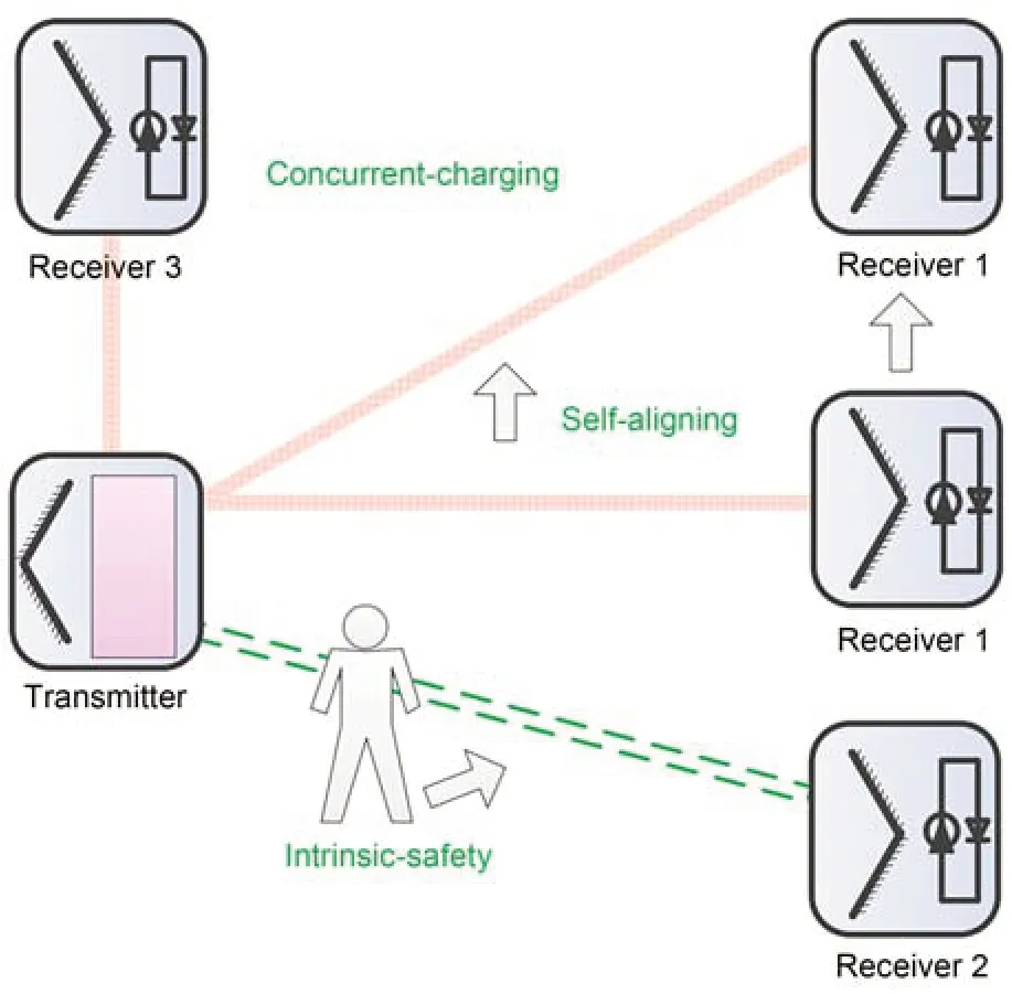
Fig.16 Distributed laser charging (DLC) features (Liu QW et al.,2016)
6.3 Adaptive distributed laser charging
In DLC,battery overcharging can lead to ther‐mal effect,energy waste,and safety concerns,while uncharging may cause capacity reduction and charg‐ing time extension.DLC is similar to WPT technology,and it can provide constant power to charge any bat‐tery.However,some batteries,such as the commonly available Li-ion batteries,require variable current and voltage.Therefore,dynamic power is required for the optimization of battery charging performance and capacity maximization.Therefore,a DLC system cannot optimize both battery charging performance and transfer efficiency.For a Li-ion battery,a slight undercharging can reduce capacity while overcharg‐ing can cause damage.It requires power control for security and optimal performance.To solve these problems,an alternative solution is ADLC or adap‐tive resonant beam charging (ARBC).It is similar to link adaptation in wireless communication,which is used to optimize information delivery.In ADLC,adaptive power is transmitted on the basis of feed‐back information from the ADLC receiver.The ADLC technique can significantly enhance energy use.There have been several studies of battery charging opti‐mization to control power dynamically to provide the required charging values.According to Zhang QQ et al.(2019a),the adaptive mechanism in DLC can save up to 61% of energy in battery charging.Zhang QQ et al.(2019b) applied the ARBC technique to provide perpetual energy to EVs in Internet of Intel‐ligent Vehicles (IoIV).Zhang QQ et al.(2017) also demonstrated an ARBC system to optimize both battery charging performance and transfer efficiency.They analyzed ADLC’s power conversion to evaluate performance and saved 60.4% of energy compared to a conventional constant power charging mechanism.Xiong et al.(2019) introduced a time division multiple access (TDMA) based scheduling algorithm,which provided flexible driving power control,individual user power control,constant driving power,concur‐rent charging,and continuous charging features.TDMA-based WPT inspires this concept of improv‐ing ADLC systems,such as quality of service and flow control.
Fig.17 presents the basic block diagram of an ADLC system,which is based on a power supply and gain medium at the transmitter site and a PV cell,bat‐tery,and a DC-to-DC converter at the receiver.The feedback system is based on a power controller and power monitor.The power monitor is used to track the battery current and voltage.The required laser power is determined by the PV cell output power and battery charging profile.The feedback information system can be designed to use infra-communication,bluetooth,or Wi-Fi.The power controller at the trans‐mitter is used to handle the feedback information.It is used to simulate different powers on the gain medium to create variable resonating beam power.There are several challenges in ADLC which must be investigated in the future.For instance,the tempera‐ture effect on the system and the effect of resonating laser beam propagation loss must be evaluated (Zhang QQ et al.,2017).

Fig.17 Block diagram of an adaptive distributed laser charging (ADLC) system
6.4 Simultaneous lightwave information and power transfer
Some studies have demonstrated the idea of SLIPT,in which networking and communication modules are incorporated within the DLC transceiver.Both visible and invisible light-aided communication methods can be implemented with the assistance of DLC to realize SLIPT (Zhang R and Ho,2013;Zhang R et al.,2015b).Moreover,both WPT and control signaling can be incorporated in a single resonating beam without any dependency on radio communica‐tion,like bluetooth or Wi-Fi.SLIPT offers the advan‐tage to transmit information and power simultane‐ously.However,SLIPT can be a source of interfer‐ence and RF pollution to data transfer.One viable approach to overcome RF shortcomings is to harvest energy from LEDs and LDs.Through an optical source,simultaneous data and energy transfer can be achieved.This strategy is mooted as a key enabler to wirelessly recharge batteries of the IoT,Intelligent Internet-of-Things (IIoT),and Internet of Underwater Things (IoUT).Researchers modified this idea call‐ing it SLIPT (Diamantoulakis et al.,2018).Recently,SLIPT has obtained significant interest as a promis‐ing technique to support WPT between communica‐tion terminals.It is a cost-efficient approach for wire‐less systems,e.g.,remote sensors and autonomous selfpowered devices.
The idea of SLIPT has been demonstrated for in‐door IoT applications and powering of IoUT devices (de Oliveira Filho et al.,2020).SLIPT can be imple‐mented through indoor VLC (Ma et al.,2019) and IR communication using a solar panel as the receiver.Pan et al.(2019) investigated SLIPT for secure commu‐nication,hybrid VLC-RF,and multiple-input multipleoutput (MIMO) techniques.Recently,Fakidis et al.(2020) performed SLIPT for 1 Gb/s GaAs VCSEL and PV link,which has significant importance for next-generation backhaul connectivity.Through pre‐cise optimization,it is possible to achieve significant gains in power transfer,spectral efficiency,interfer‐ence management,and reducing time delay and energy consumption.This technique also provides a signif‐icant trade-off between rate and harvested energy (Diamantoulakis et al.,2017).MIMO VLC (Fig.18) can be used in MIMO SLIPT VLC to achieve a suit‐able trade-off among cost,data transmission,and en‐ergy harvesting (Pan et al.,2019).
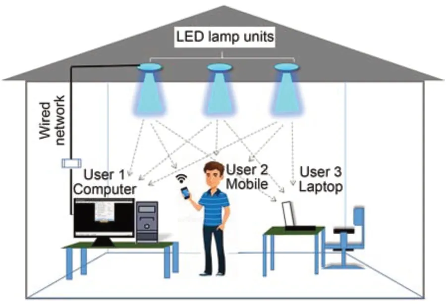
Fig.18 Multiple-input multiple-output visible light communication
6.4.1 SLIPT for IoUT
Recently,SLIPT has been proposed for power‐ing IoUT devices.The motivation behind this is the rapidly growing demand for underwater communica‐tion systems because of ongoing expansion of marine activities such as offshore oil field monitoring,under‐sea earthquake monitoring,scientific data collection,underwater exploration,marine current power grid connections,pollution tracking/control,and marine life observation.Underwater data transmission can be achieved using optical,radio,and acoustic waves.Generally,acoustic communication is used for under‐water applications as it can cover several kilometers.The associated frequency range for acoustics is 10 Hz to 1 MHz.However,it is prone to limited bandwidth,low propagation speed,and high latency.Moreover,RF waves can propagate over a large distance with low frequencies (30‒300 Hz) and suffers badly from attenuation.RF waves are not sufficient for practical applications as they need high power and large anten‐nas.In contrast,underwater optical wireless commu‐nication (UOWC) provides high transmission data in several Gb/s with large bandwidth.SLIPT has emerged as a complementary technology to UOWC for both wireless charging and continuous connec‐tivity in harsh ocean environments.Multiple theoreti‐cal and experimental SLIPT studies in free space have been reported,but only a few have discussed under‐water media.SLIPT in underwater media is yet to be explored.In a previous study,an underwater commu‐nication link was designed with a 5 cm2solar panel as the receiver in a 7 m long water tank.Kong et al.(2019) demonstrated a VLC system using AquaE-lite,white laser,and Si thin film solar cells in 20 m of air and 2.4 m of turbid poor water.de Oliveira Filho et al.(2020) reported energy harvesting and communica‐tion scenarios in an underwater environment.Charg‐ing was achieved by light beams emitted from a boat or autonomous underwater vehicle (AUV).The battery of a submerged module can be recharged by turbidity or temperature sensors.The major issues in deploy‐ing SLIPT-based underwater devices are pointing,acquisition,and tracking (PAT) requirements,but these can be minimized using a solar cell as a photo-detector.A much greater research effort is needed from the re‐search community to overcome channel-related issues and other major technical challenges before widescale underwater deployment can be achieved.
6.4.2 Open issues in SLIPT
There are several challenges related with differ‐ent SLIPT techniques,which are associated to either a propagation effect over wireless underwater media or the hardware,such as battery lifetime and the band‐width of the solar cell.Here we discuss open issues and propose solutions for future research directions.
1.LOS issue.One of the critical challenges for underwater SLIPT is an obstructed propagation path.This can be removed by enhanced UV scattering to establish an NLOS path.However,it needs a solarblind solar cell for energy harvesting from UV light.A deep understanding of this technique is required to tackle safety challenges from UV exposure.
2.Beam divergence.During propagation in an unguided medium,the light beam diverges.This leads to an increase of radius.Losses because of beam di‐vergence are referred to as geometrical attenuation.Such losses are related to the LED or LD source,op‐erating wavelength,and propagation distance.Beam divergence must be taken into account for SLIPT sys‐tems.The designed system should maximize the cap‐ture of incident light,and received power must fulfill both the communication and power transfer functions of SLIPT.
3.Propagation effects.As light propagates through water,the light intensity decreases exponentially.A light beam can also face turbulence,which is due to air bubbles,salinity variation,and temperature fluctu‐ations.Salinity variation and temperature inhomoge‐neity cause rapid variation in the refractive index of water,while air bubble can partly or fully block a light beam.Some studies have proposed statistical channel modeling to find the impact of turbulence on UOWC systems.To perform SLIPT functions in an underwater channel,turbulence and attenuation must be taken into account for high performance of both SLIPT functions.The impact of turbulence can be reduced using multiple wavelengths for energy harvesting and communication purposes.Continuous connectivity of devices can be achieved using differ‐ent wavelengths.Different wavelengths can be used to send different data streams and a power splitting ap‐proach can be used for battery charging.
4.Hardware challenges.Another limiting factor for SLIPT performance is the bandwidth of the re‐ceiving component.The bandwidth of commercially available solar cells is limited to dozens of kHz.The restriction on the data rate can be alleviated using ad‐vanced modulation schemes,like Mary quadrature amplitude modulation (M-QAM) orthogonal frequency division multiplexing (OFDM).In addition,the transmission capacity can be improved by a power split‐ting SLIPT approach in which a PD is used at the re‐ceiver instead of a solar cell.A high bandwidth PD can be used at the expense of a pointing error,as it has a small detection area compared to a solar cell.Addi‐tional hardware challenges are associated with the bat‐tery lifetime of IoUT devices.
6.5 Fly-eye lens system for OWPT
Katsuta and Miyamoto (2019b) constructed a fixed OWPT system to transmit 10 W power over a 2 m transmission distance.They added a fly-eye lens to the OWPT system,and developed a technique for solar cell irradiation with multiple optical sources of high frequency.Previously,they had reported work on optimization of the fly-eye lens system (Katsuta and Miyamoto,2019a).In their proposed configura‐tion,a solar cell was attached with a fly-eye lens.A high-power single-chip VCSEL array was used as it was commercially available with 20‒40 W output power.A fly-eye lens system contained several small single lenses in the form of a 2D array (van Giel et al.,2007).A schematic of the fly-eye lens system can be seen in Fig.19.By embedding a pair of fly-eye lenses,the incident optical beam over the fly-eye lens was split by the array lens,and then the imaging lens was used to image the beam on the irradiation surface.In the proposed system,uniform intensity distribution can be achieved by irradiating light of a similar ge‐ometry to a single lens.In this fly-eye lens system,various optical sources can be used and each optical source was at an arbitrary position.Due to this char‐acteristic,fly-eye lenses were used for semiconductor manufacturing equipment and projectors (Kasazumi et al.,2004).In an OWPT system,a fly-eye lens ap‐pears to be a promising approach to obtain uniform intensity distribution and a rectangular irradiation pat‐tern at a distant point from an optical source,with high efficiency.

Fig.19 Overview of a fly-eye lens system in OWPT (Katsuta and Miyamoto,2019b)
Katsuta and Miyamoto (2019b) have presented a fly-eye lens system with a different configuration.As in an OWPT system,light leakage occurs outside the solar cell,which decreases the transfer efficiency.Therefore,a precise alignment between transmitter and receiver modules is needed.This causes an in‐crease in the expenditure of installation and degrada‐tion of performance because of misalignment through aging.By designing a system to maintain tolerance of positional misalignment,it is possible to over‐come aging deterioration and alignment precision.A passive mechanism is required,as this configuration becomes complex while using an active mechanism.The proposed configuration involves an optical sys‐tem of a fly-eye lens incorporated with a solar cell (Fig.20).In this configuration,light irradiation is achieved within the size of a fly-eye lens,and trans‐mission distance is not dependent upon the focal length of the imaging lens.This use of a fly-eye lens in an OWPT system provides uniform irradiation and re‐duces light leakage outside the solar cell.This results in an effective method to expand usage conditions,and can support the installation precision required for an OWPT system.This structure can enhance the allowable incident angle and positional shift,and can adjust the transmission distance.
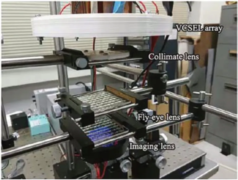
Fig.20 Experimental demonstration of the fly-eye lens (Katsuta and Miyamoto,2019b)
6.6 OWPT system by spatial wavelength division and distributed laser cavity resonance
Spatially distributed laser cavity resonance is a promising solution for optical charging systems.In this scheme,optical power is transmitted over a 2D field of view busing two orthogonal diffraction gratings.This scheme allows wavelength bands to be distrib‐uted to optoelectronic devices across space (Oh et al.,2016).A diffraction grating is used in the transmitter part to spatially disperse the light from a semicon‐ductor optical amplifier (SOA).At the receiving unit,multiple resonant cavities are formed using retroreflecting beam splitters to reflect the incident beam back to the transmitter.Retroreflectors tap power from the resonant cavities by enabling a user-friendly alignment.An automatic safety mechanism can be incorporated to cease the cavity resonance if any vul‐nerable object breaks the LOS between the trans‐mitter and receiver candidates.A drawback of this technique is the limit to high power radiated by the maximum permissible exposure (MPE) defined by the International Electro-technical Commission (IEC) (IEC,2007).A spatially distributed resonator laser system was reported which has a planned path to com‐mercialization.According to relevant PCT patents (US8525097B2 and US9225140B2) (Kim SM and Kim,2013a),we can summarize this technology as follows: a light beam is reflected using retro-reflecting components in the receiver element,and retraces the incident light beam path back to the transmitter com‐ponent.It supports the addition of components within the cavity to configure beam parameters or amplifi‐cation.When the LOS path between transceivers is blocked,power transmission is immediately stopped.When the path is restored,high optical power is trans‐mitted to distant receiver components.As a proofof-principle,Lim et al.(2019) carried out experiments for DLC by merging the ideas of distributed laser cavity resonance and diverging angular dispersion.They used an SOA to enable a broadband gain spec‐trum,a diffraction grating for angular dispersion of IR light of different wavelengths,and a retroreflector to reflect the light beam to the SOA to establish a reso‐nant cavity.The proposed OWPT system is shown in Fig.21.This OWPT system employs diverging angu‐lar dispersion and distributed laser cavity resonance to enhance the WPT,with fewer hazards.The system is based on the use of a transmitter unit to accommo‐date multiple receiver units.A gain medium is used to amplify power,a diffraction grating for angular dis‐persion,and a telescope to distribute it over a wide field-of-view (FOV).The receiver includes a retroreflecting beam splitter to reflect a narrowband light to the transmitting unit,developing a resonant chan‐nel which stimulates laser excitation.In the case of hazard-prone objects interfering with the LOS,a safety mechanism is incorporated to reduce the power emis‐sion from the transmitter.With FOV optimization and careful retroreflector design,this novel design can be exploited for commercialization.

Fig.21 A schematic of the proposed OWPT system (Lim et al.,2019)
6.7 OWPT-based rapid charging
Raavi et al.(2013) presented an OWPT system to deliver power to mobile portable devices.The system contained an optical antenna,a DC-DC converter,and a commercially available GaAs solar cell.A nanostructured optical antenna embedded with a GaAs solar cell expedited the charging process to employ a plasmonic electric field enhancement effect.A singlejunction GaAs solar cell was developed to achieve high efficiency,while maximizing the output power.A step-up DC-DC circuit was used to obtain the required DC voltage and stable current from the solar cell for recharging batteries of portable devices.It was an effi‐cient,compact,and secure OWPT system.This sys‐tem can achieve fast and smart charging over long distances,while ensuring high efficiency and compli‐ance with human safety regulations.The proposed OWPT system is presented in Fig.22.The optical sources are attached to the room ceiling and emit light beams compliant with FCC human safety regu‐lations.The central station linked with the optical sources receives the pilot signal from charging devices and adjusts the activation and deactivation process of optical sources.The mobile devices to be charged con‐tain an optical antenna embedded with a solar cell and a DC-DC circuit.These devices can be installed at any point in the room to receive optical energy.
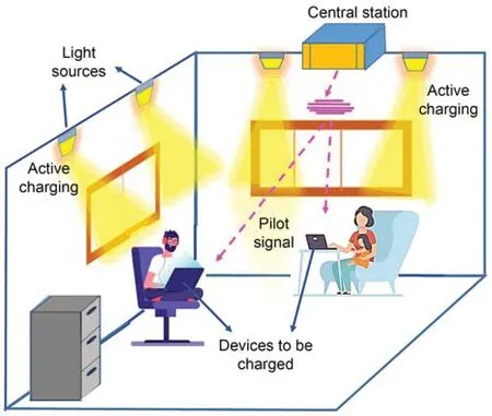
Fig.22 A schematic overview of the wireless energy transfer system
An innovative technique for rapid charging is to amplify the power density of light using a PV semi‐conductor device with an optical antenna.GaAs is selected due to its high efficiency and absorption coefficient.In this solar cell structure,both the p-AlGaAs window layer andn-AlGaAs layers reduce the surface recombination.An anti-reflection coating is required to suppress the reflection,which can be as higher as 20%–30%.The photon confinement by the optical antenna can reduce the emitter and base thick‐ness to enhance the efficiency of excited minority carriers.The amplification achieved by the optical an‐tenna is 2–3 times higher and is not restricted by the principles of geometrical optics.A performance com‐parison with and without an optical antenna is shown in Fig.23,which indicates a clear increase in output power.
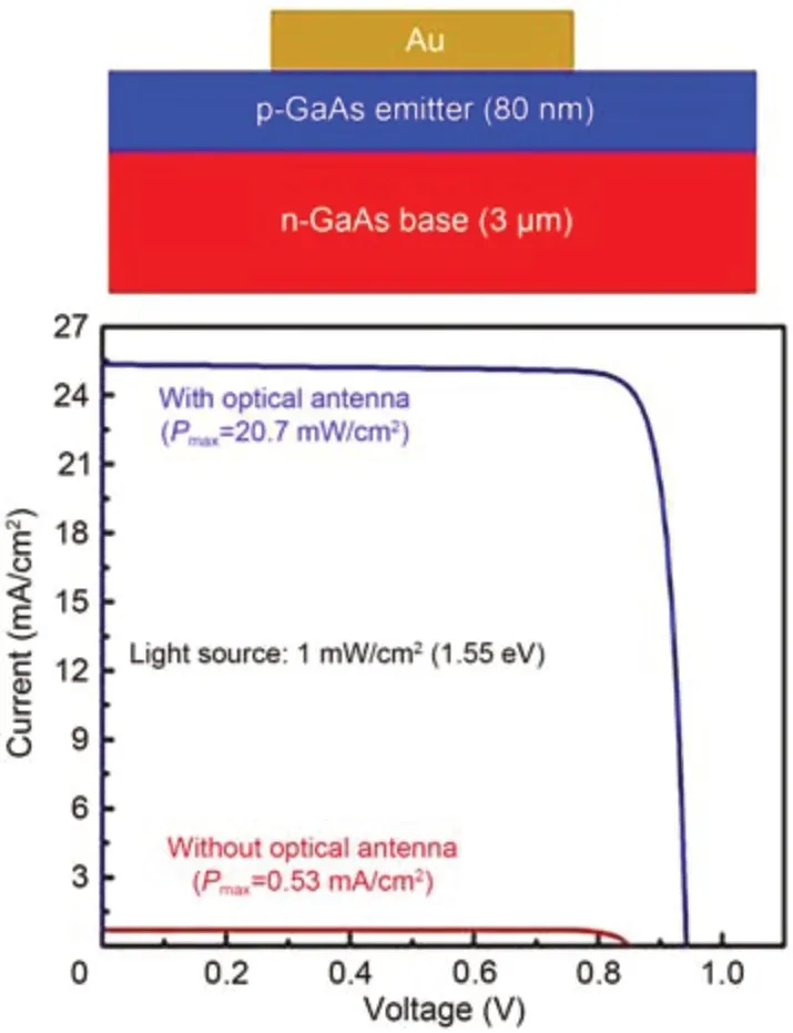
Fig.23 Maximum output power from a single-junction GaAs solar cell incorporated with and without an optical antenna (Raavi et al.,2013)
6.8 Thing-to-Thing OWPT
Recently,Nguyen et al.(2020) have demonstrated a novel OWPT system for objects,either mobile or stationary.Unlike existing OWPT systems,in which the transmitter and receiver are two different devices,this novel conceptual system deploys only a single device (optical transceiver),which performs both tasks of light absorption and emission.In this proposed system,things/objects are partly or fully covered by perovskite transceivers to enable wireless charg‐ing or discharging functions.This idea removes the unidirectional WPT limitation and supports bidirec‐tional OWPT between both mobile and stationary ob‐jects.The proposed OWPT system is presented in Fig.24.The system is composed of a transmission medium,e.g.,air,outer space,or seawater,and devices on which optical transceivers are deployed.The opti‐cal transceiver is fabricated from lightweight,thin,flexible,and low-cost metal halide perovskite.The flexibility characteristic of a perovskite transceiver makes it adaptive to any surface.Metal halide pero‑vskites offer several advantages including compati‐ble to low-cost solution processing,bandgap tenabil‐ity,high absorption coefficients,large carrier diffu‐sion lengths,and high carrier mobility.The maximum PCE of perovskite solar cells is 25.2% (Park and Zhu,2020).Moreover,perovskites can be used as emitters of LEDs due to their efficient photolumines‐cence feature.Recently,over 20% external quantum efficiency has been reported with perovskite LEDs (Lin KB et al.,2018).
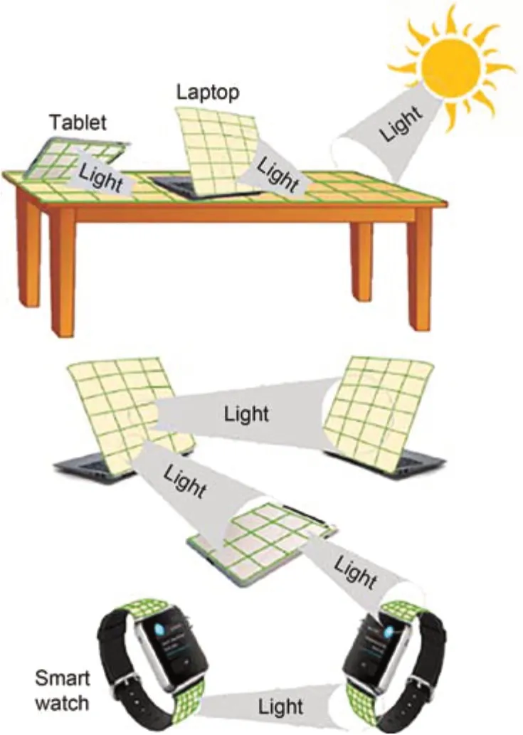
Fig.24 The proposed T2T OWPT system (Nguyen et al.,2020)
6.9 High intensity laser power beaming
HILPB is a promising technique for long-range WPT for both terrestrial and space applications.In an HILPB system,a high-power LD source is used because of its excellent characteristics of small size,high reliability,and high efficiency.A schematic block diagram of HILPB is shown in Fig.25.The transmitter converts power into a monochromatic light beam through an LD.This laser beam is directed towards a solar panel via a beam director.At the receiver,the optical signal is converted to electric power.In practi‐cal HILPB systems,the system performance is re‐stricted by the conversion efficiency of the light source and receiver.Since each component has a fundamental role in the overall system efficiency,high-performance components are chosen for designing an efficient system.
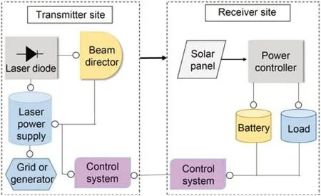
Fig.25 A schematic of a high intensity laser power beaming system
HILPB technology is capable of transmitting energy to remote mobile devices,e.g.,robots,UAVs (Raible,2008),and satellites (Nayfeh et al.,2011).It can be used for optical refueling of resourceconstrained platforms which use electrical energy as sources of propulsion and capability.In addition,HILPB has the ability to connect power plants,land‐ing sites,and lunar habitats.The extensive applications of the HILPB system make it an attractive endeavor for a complete WPT system,but every component must ensure high end-to-end efficiency.There was little research interest in HILPB until a variety of LPT projects were developed in the 2000s.Steinsiek (2003) designed a laser-based minirover for space exploration missions.They demonstrated this project with an Nd:YAG 532 nm laser with 5 W output power.An orthogonal angle between the laser beam and the PV cell was maintained through a tracking system over a 280-m distance.Then,in 2003,researchers from NASA demonstrated a laser-based aircraft flight (Raible,2008).The aircraft was fitted with 1.5 kW diode at 940 nm and a thin film PV array.Researchers from Kinki University,Japan developed a laser-based small airplane (Kawashima et al.,2007),and a laserbased robot (Kawashima and Takeda,2008).Becker et al.(2010) designed an HILPB-based robot climber for the NASA Centennial Challenges.He et al.(2014) from Beijing Institute of Technology,China demon‐strated a laser-based WPT system operating at 100-m distance using a PV converter.In 2016,Russian sci‐entists successfully implemented cell phone charging at 1.5 km using a laser and PV converter.The Rus‐sian Academy of Cosmonautics intended to apply this LPT technology to military vehicles and satellites (Jin and Zhou,2019).Table 4 summarizes some HILPB systems.

Table 4 Different high intensity laser power beaming systems
7 Transceiver selection in OWPT
In this section,we discuss hardware technolo‐gies,such as laser and PV cells,which enable OWPT.In our end-to-end discussion,the appropriate selection of these components is important.Understanding these devices and their capabilities is crucial for de‐signing an efficient OWPT system.
7.1 Laser selection
The American National Standard for Safe Use of Lasers (ANSI Z136.1) (Rockwell et al.,2015) pro‐vides instruction for the installation,safe operation,maintenance,and service of lasers for optical com‐munication systems.It gives guidelines for laser se‐lection and safety operations throughout the USA,in‐cluding the market,government,and academic sectors.The above reference contains important information about laser selection,safety concerns,and standard operations.Currently,different types of lasers are com‐mercially available.Accurate selection of the laser must comply with several constraints including (1) OWPT through different environments and (2) the maxi‐mum target transfer energy.The transmission medium requires selection of a laser with an appropriate wave‐length.The laser must operate with maximum energy transfer for the high performance of any OWPT sys‐tem.Duncan (2016) reported laser-empowered ele‐ment selection in which the 780 nm and 1100 nm re‐gions were appropriate for commercially available laser technologies.Similarly,the spectral windows of 800,900,and 1500 nm are preferred for power beam‐ing to UAVs.The main factors of lasers contain:
1.Directionality: Generally the laser light pro‐vides a low divergence (Silfvast,2004).
2.Coherence: The emitted photons show con‐stant phase coherence.
3.Monochromaticity: A laser beam contains a narrow range of wavelengths.
Table 5 summarizes existing laser technologies,and presents different laser types which support beam‐ing in dozens of kilowatts (Mason,2011).The diodepumped solid-state lasers (DPSSLs),like disk and fiber lasers,are good for high-power and long-range LPT systems as they support both beam quality and high power.A few high-power lasers are commercially available (Iwai et al,2009;Alsulaiman et al.,2014).On the other hand,high-power LDs are more com‐pact,cost-effective,and efficient as compared to DPSSLs.In addition,safety concerns are essential while performing LPT experiments.Most lasers are hazardous for human skin and eyes.An LPT system with low power levels can also pose a safety risk,and thus it is challenging to design a hazard-free inhouse charging system (IEC,2007;Sahai and Graham,2011).Computer models have been developed to pre‐dict the injury threshold at different wavelengths (Jean et al.,2021).Table 6 summarizes eye safe lasers,and Table 7 summarizes the related standards for eye safety of laser products (Soltani et al.,2021).
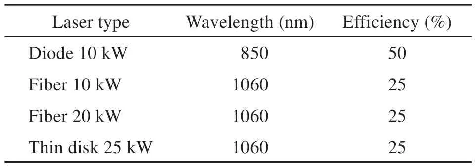
Table 5 Existing laser technologies (Mason,2011)

Table 6 Eye safe lasers (Kaushal and Kaddoum,2017)

Table 7 Related standards for eye safety of laser products (Soltani et al.,2021)
A high-efficiency high-power semiconductor light source is effective as an optical transmitter for OWPTsystems.LD is preferred to generate collimated light.The other optical sources have low power conversion efficiencies,except LED.Some LEDs are also more efficient than LD,but their light use efficiency is still limited.An interesting optical source for an OWPT system is a VCSEL (Fördös et al.,2018).It has charac‐teristics of a scalable array size and optical output by 2D array (Seurin et al.,2013).Moreover,a VCSEL is preferred for catastrophic optical hazard-free oper‐ation (Moser and Latta,1992).Commercially avail‐able GaAs and Si solar cells are suitable for its beam reception.Reported efficiencies of EELs and VCSELs are presented in Fig.26.A plot of the historical power conversion efficiencies of VCSELs is presented in Fig.27.Semiconductor lasers (Welch,2000) are the subject of extensive research and their efficiency has been dramatically improved by up to 70% at around the wavelength of 0.9 µm (Crump et al.,2007).Effi‐ciency is 40% or higher in the wavelength range of 0.4 to 1.5 µm.The efficiency of VCSEL is slightly lower and reaches a maximum of 60% in the range of 0.8‒1.1 µm (Kageyama et al.,2009).Liu PQ et al.(2010) have introduced a highly power-efficient quan‐tum cascade laser.However,improvement in the over‐all efficiency of the laser is not so easy.As OWPT sys‐tems do not require a single longitudinal wave‐length,single transverse mode,or high modulation frequency,it may be possible to improve efficiency in the future by further exploring suitable optical sources.
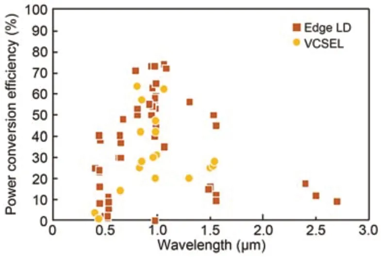
Fig.26 Summary of the reported power conversion efficiency (PCE) of semiconductor lasers (edge LD and VCSEL) (Miyamoto,2018)
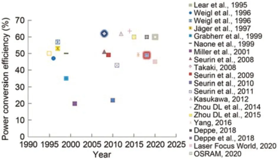
Fig.27 Historical plot of the vertical cavity surface emitting laser (VCSEL) efficiency (Lear et al.,1995;Weigl et al.,1996;Jäger et al.,1997;Grabherr et al.,1999;Naone et al.,1999;Miller et al.,2001;Seurin et al.,2008,2009,2010,2011;Takaki,2008;Kasukawa,2012;Zhou DL et al.,2014,2015;Yang,2016;Deppe,2018;Deppe et al.,2018;Laser Focus World,2020;OSRAM,2020)
7.2 PV cell selection
The receiver element of any OWPT system must be intelligently developed to efficiently convert optical signals into electrical signals.The most traditional conversion techniques are thermoelectric,PV,and py‐roelectric.Among these techniques,PV technology is known as the most mature,as it offers the highest efficiency to deliver high power over far distances.To achieve high performance,temperature,PV cell ma‐terial,laser power,and wavelength must be kept into consideration.In addition,the photon energy is as‐sumed to be equal to or more than the bandgap energyof the material for any PV cell receiver.This photon energy is proportional to its frequency.Thus,a mono‐chromatic optical source with ideal frequency is tak‐en as an ideal light source.The spectral response of different PV cells is shown in Fig.28 (Mason,2011).
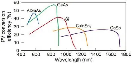
Fig.28 Spectral response of photovoltaic (PV) materials (Mason,2011)
It can be noticed from the graph results that the commonly available Si and GaAs PV cells provide the highest conversion efficiencies at 900 and 850 nm,respectively,while AlGaAs provides the highest re‐sponse over 550‒600 nm.Moreover,a PV cell offers an effective response for a given temperature with generating more power if an intense light beam is incident on it (Höhn et al.,2016).Thus,we can con‐clude that PV cells efficiently work at high laser power intensity.In particular,GaAs (Matsuura et al.,2021) and Si (Putra et al.,2019) are commonly used,but it is also essential to choose the optical receiver accord‐ing to the wavelength of the transmitter in order to improve the system’s efficiency.
Table 8 summarizes the efficiencies of various PV materials when they are illuminated by different laser sources.The GaAs PV cell has the highest effi‐ciency around 850 nm wavelengths (Valdivia et al.,2015).A Si PV cell has the highest efficiency around 900‒950 nm wavelengths,but this region faces severe atmospheric absorption (Mason,2011).On the other hand,InGaP and InGaAs are ideal for DPSSLs as they show the highest efficiency at wavelengths greater than 1000 nm.

Table 8 Efficiencies of various PV materials (Valdivia et al.,2015)
Miyamoto (2018) calculated the wavelengthdependent PCE of a solar cell (Fig.29).He stated that the wavelength of the optical source can be al‐tered according to the bandgap energy of the solar cell to minimize thermal loss in any OWPT system.It is clear from Fig.29 that the bandgap energy varies according to the wavelength of the irradiated light.High efficiency can be achieved at high irradi‐ation optical power density and with a short wave‐length range.The thermal heating of the solar cell lim‐its the irradiation power.Photodetectors can also be used at larger wavelengths,but their narrow bandgapenergy (Eg) puts a limitation on PCE.There have been few studies using short wavelengths of UV and blue light,as this range is not suitable for solar power sys‐tems.Thus,researchers should focus on designing spe‐cific OWPT systems (Fafard et al.,2016;Perales et al.,2016) and widegap solar cells for a better PCE.
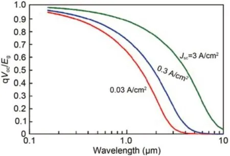
Fig.29 Calculated power conversion efficiency (PCE) of a solar cell for various wavelengths and irradiation optical power (Miyamoto,2018)
Fortunately,the high efficiency wavelength of an LD matches theEgof the commercially available solar cells GaAs (λg=0.88 µm) and Si (λg=1.1 µm).Thus,the combination of these materials and corre‐sponding wavelengths is practical.Table 9 summarizes OWPT efficiencies of current and future devices (Miyamoto,2018).Currently,10%‒20% efficiency is possible through commercially available devices,while the best devices were reported to achieve almost 50% efficiency.These efficiencies are sufficient for systems which do not require higher efficiency for their oper‐ation.Moreover,70% or higher efficiency is expected by improving the efficiencies of both the LD and solar cell.However,this performance requires a lot of effort by the research community in research on widegap optical sources and solar cells.

Table 9 Efficiencies of various PV materials (Miyamoto,2018)
Recently,Ishikawa et al.(2020) from Tokyo City University,Japan evaluated the use of bromide-based perovskite flexible thin film solar cells to develop an OWPT system.Bromide-based perovskite has a high bandgap of 2.3 eV,which makes it suitable for solar cell applications.The flexible thin film solar cells pro‐vide good performance under monochromatic light,with efficiency of more than 20%.High-efficiency perovskite silicon tandem solar cells (Todorov et al.,2014;Sahli et al.,2018) have also emerged as pro‑mising candidates for OWPT (Schubert et al.,2009) and IoT devices (Raifuku et al.,2016).The Shockley and Queisser theory shows that the open-circuit volt‐age (Voc) of a solar cell is a linear function of the band‐gap energy.Therefore,ifEgincreases then the maxi‐mum voltage efficiency also increases.For OWPT applications,the CsPbBr3 system offers some advan‐tages,including thermal stability.In a recent research (Ishikawa et al.,2020),the MAPbBr3 system has shown the best optical properties among wideband perovskite materials.An efficiency of 20.2% under blue LED has been achieved by high-quality MAPbBr3.A research group from Tokyo City University is also working on OWPT applications of CsPbBr3 (Murata et al.,2020).
Current,most solar cells are designed to capture sunlight.In such conditions,the surface of the solar cells appears to be black after absorbing light of vari‐ous wavelengths.In OWPT applications,this property of solar cells becomes a potential obstacle.Typically,the solar surfaces are black,which restricts the visi‐ble appearance of OWPT devices.
In an OWPT system,the optical source is ef‐fective monochromatic light from a laser or LED,which is different from common sunlight.The wave‐length of the optical source is chosen according to power transmission properties.At present,the IR range is considered optimal for mature GaAs and Si solar cells.Even though there are several restrictions and conditions,it is feasible to alter the appearance of a solar cell using color filters.Visible color filters can be applied to alter the common black appearanceof a solar cell to enhance the visual appearance of consumer appliances,without compromising the effi‐ciency of the solar cell.
Different kinds of filters are available,based on their absorption: sharp wavelength cut filter (SCF),visible dichroic filter (DIF),and visible dichroic mirror (DIM).The colors of the different filters are shown in Fig.30.

Fig.30 Colors of DIF-MAG (a),DIF-YEL+SCF-52Y (b),DIM-GRE+SCF-52Y (c),and DIF-RED+SCF-52Y (d)
A research group from the Tokyo Institute of Technology,Japan applied frosted glass to alter the rough surface of a solar cell to obtain light scattering.They concluded that the typical appearance of OWPT can be altered with an acceptable low deterioration in performance.Although filters can change the color,they are not enough to control the overall appearance.Thus,Liu Y and Miyamoto (2019a) applied frosted glass to achieve light scattering,which can enhance the appearance characteristics.Anti-reflection coated devices can be applied to enhance the performance of OWPT systems in the future.In a previous study (Liu Y and Miyamoto,2019b),a connected thin film GaAs solar cell was fabricated using a 3D printer.Fig.31 shows two color filters,DIF-RED and DIM-GRE,with and without frosted glass.The module surface became smooth and the appearance was improved after adding frosted glass.

Fig.31 OWPT light receiver module without (a) and with (b) frosted glass (Liu Y and Miyamoto,2019a)
8 Challenges and counter measures in OWPT
This section highlights several critical challenges for OWPT.We briefly discuss challenges associated with efficiency,safety,communication,propagation losses,thermal effects,beam collimation,and the pointing issue.We also suggest some solutions to overcome these challenges.
8.1 Efficiency improvement
Improving the efficiency of any OWPT system is a challenging task.With the expanding advance‐ments in OWPT,its use cases are increasing.The overall efficiency is not suitable for its commercial development as HILPB systems provide efficiency of only around 10%‒20%,which is a great hurdle.The research fraternity is focusing on efficiency improve‐ment for commercial deployment and researchers are working to improve PV cell efficiency.In 2003,the US Department of Defense (DoD),under the Defense Advanced Research Projects Agency (DARPA) Super High Efficiency Diode Sources (SHEDS) program,dedicated significant research and resources to improv‐ing the efficiency of LDs to 85%.
8.2 Safety
At present,laser technology is being implemented in hospitals,offices,and private enterprises.Therefore,it is critically essential to introduce a laser-safe envi‐ronment.Inappropriate usage of laser devices can cause hazards,including irreparable injury to the skin and eyes.The biological hazard occurred by la‐sers is due to thermal,photochemical,and acoustical effects.Thus,it is important to design stringent safe‐ty solutions,like scanning light detection and rang‐ing (LIDAR).Thus,precautionary steps must be taken to mitigate retinal damages.A possible solution is to consider larger wavelengths beyond this region.How‐ever,it incurs complacency,low efficiency,and high cost.It is imperative to design laser safety guidelines and regulations.This involves accurate control,effec‐tive hazard analysis,laser safety analysis,and knowl‐edge of laser regulations (IEC,2007).Effective haz‐ard analysis includes many parameters,as discussed below.
8.2.1 Maximum permissible exposure and accessible emission limit
The MPE defines an accurate number for laser safety calculations: it is the lowest radiant exposure or irradiance that does not cause any biological damage to human eyes or skin.It is a function of ex‐posure time and laser wavelength.It is the highest power in W/cm2that is non-hazardous for specific exposure conditions.MPE and exposure time variation for common laser wavelengths is shown in Fig.32.

Fig.32 Maximum permissible exposure (MPE) vs.exposure time (Sun et al.,2019)
Another crucial factor is the accessible emission limit (AEL),which refers to the maximum radiation power that can be emitted from a particular laser.It is used to classify lasers,but does not define system safety.The AEL value should be kept into account for the proper use of lasers.For instance,if we keep the power level below a certain threshold,any unin‐tentional exposure to the laser beam will not cause any hazard.
8.2.2 Laser beam control measures
Direct beam exposure can be substantially re‐duced by accurate safety constraints built into the system.The presence of any object within the fieldof-view of a laser is crucial.Sufficient time is re‐quired before any object appears into the proximity of the optical beam path.In these conditions,suitable engineering control mechanisms are needed that can accurately attenuate or terminate the optical beam.Beam control is also important,as the receiver can reflect some part of the incident optical power.The receiver part contains a gimbal sensing mechanism that can reduce the reflected energy to redirect it into a safe dissipation area.Furthermore,mobile and endto-end OWPT systems should be designed to over‐come reflection and redirect this optical power into any absorber target,to avoid any damage.
8.2.3 Nominal ocular hazard distance
The nominal ocular hazard distance (NOHD) (de Luca et al.,2012) refers to the distance from the source where the MPE is equal to the radiation.Here,the energy at a distance smaller than the NOHD is equal to or lower than the MPE limit,while distances longer than the NOHD are called nominal hazard zones (NHZs).The value of NOHD is calculated using the ANSI Z136.1 standard,to find the safe re‐gions near the laser.In addition,physical laser precau‐tionary measurements should be taken into account.Eye wear is also specific for lasers.An important pa‐rameter of eye wear is the optical density (OD) of the lens,which is a function of the irradiance and power and affects the attenuation of energy passing through the eye wear lens.Correctly selected eye wear will attenuate the beam to a level below the MPE limit.
8.3 Optical communication
In the future,LPT technologies such as HILPB will integrate efficient optical communication.By using a PV cell as a receiver to ensure communica‐tion,data can be transferred along with power trans‐fer,resulting in a dual-application system.A tech‐nique to integrate a communication link onto trans‐mitted photon energy will introduce cutting-edge ro‐bust free space optical communication.However,it is still a crucial concern to integrate a communication link into an optical power link.
8.4 Propagation losses in the optical beam
Three factors of free space usually limit the performance of the optical system: (1) expansion of waves beyond the capability of the optics to colli‐mate,(2) distortion of wave fronts because of varia‐tion in the refraction index of air,which is influenced by gradient caused by wind and temperature,and (3) dust and water particles,which scatter or absorb photons.
Absorption and scattering coefficients alter ac‐cording to the sizes of airborne particles.In normal situations,absorption and scattering do not pose severe effects such as those caused by atmospheric gradi‐ents and distance.Distance is a prominent parameter that causes severe impacts on beam transmission.The laser mode structure is the appropriate determinant of optical power over distance.In common cases,two different kinds of lasers are considered,single-mode and multi-mode.Single-mode lasers,e.g.,disk laser,are used to transmit optical power up to 1 km dis‐tance.However,it is hard to reach the diffraction limit by multi-mode lasers.Therefore,both have cer‐tain limitations.
8.5 Thermal effects on system performance
As lasers perform better in colder conditions,it is essential to remove heat.The PCE is better in a cooling environment.Crump et al.(2006) demon‐strated a PCE of 76% at 10 ℃,and up to 85% at −50 ℃ for a 975 nm broad area LD.At ambient temperature,a heatsink arrangement can be a good choice.We need to be careful for specific lasers such as a C-Mount laser,which is not good at removing heat.Thermal heat also degrades the overall perfor‐mance of the optical system.Lasers and PVs are dif‐ferent from silicon integrated circuits as they show sensitivity to heat.A 14XX InP laser loses efficiency at 1.1% per degree Celsius of heat,while a 12XX quantum dot laser loses efficiency at 0.6% per degree Celsius.Nowadays,these lasers are not available beyond 1400 nm wavelengths.Heat also reduces the PV voltage.So,it seems that a proper way to reduce thermal effects and sink heat from packages is the key objective.Fig.33 shows the thermal effect on a multi-mode InGaAsP/InP 1400 nm edge-emitting LD.
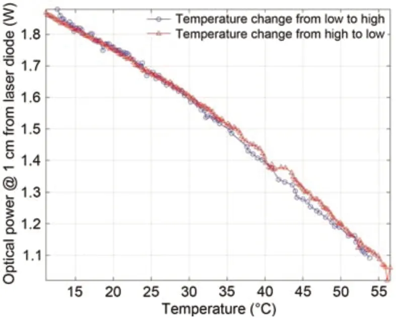
Fig.33 Thermal derating of a multi-mode edge-emitting InGaAsP/InP LD (Sahai and Graham,2011)
Thermal degradation of PV cells is also impor‐tant.Usually,limited power is available at the receiver site for a power beaming system.Thermal perfor‐mance can be enhanced using efficient materials which operate near match points with a better interconnec‐tion.A fan can be incorporated as another suitable alternative.
8.6 Pointing
There should be accurate pointing between the transmitter and the receiver.For a 10-m distance,with a tolerance of +3 mm or −3 mm at the receiver,the system should point within 0.3 mrad.A good me‐chanical design is required to lock the device without jostling it at this close tolerance.In addition,the threads of off-the-shelf machine nuts and screws lack proper consistency in some systems.It is suggested that the receiver should point at the transmitter de‐pending upon the accurate optical arrangements.
8.7 Collimation of multi-mode lasers
1.Fast axis collimation.Collimating a fast diver‐gence beam is difficult.A relatively large amount of light is lost if a high-powered laser beam is 40° be‐yond the axis.An aspheric lens is a suitable option for the collimation of fast beams,as it can adjust the two axes differently.
2.Slow axis collimation.Collimation of a multimode laser is also complicated,as it has many hori‐zontal modes.The beam size will vary with the dis‐tance.To ensure safe operation,it is required that the beam should not appear to a focus at any specific range,and thus adjusting this divergence is hard.
9 Conclusions
WPT technologies are still in their infancy,and require a deep research focus and wider investiga‐tions in the context of reliable consumer electronics and realistic mobile devices.Among WPT techniques,OWPT offers several advantages in terms of sending power in underwater environment and implantable devices inside human skin.It has the potential to trans‐mit high intensity light over longer distances due to its small divergence angle and beam size.However,it requires an additional element for beam steering,as the laser beam must be steered at the receiver.For IoT terminals such as beacons,tags,and sensors,physical wires and batteries are not effective due to their complexity,installation,and maintenance costs.OWPT is a promising alternative to traditional charg‐ing mechanisms with its potential features of small beam size,good directionality,and long-distance transmission.
In this study,the basic concepts of OWPT have been presented.In particular,the OWPT working principle,system design,potential features,and vari‐ous OWPT projects for mainstream applications are discussed.We have also suggested that OWPT is an essential element to supply power to IoT terminals.We have highlighted the impacts of dynamic OWPT.Moreover,our study dealt with the rudimentary physics of OWPT technologies including optical beamform‐ing,DLC,ADLC,SLIPT,HILPB,and T2T OWPT.We also shed some light on research efforts dedicated to these OWPT technologies.Besides introducing the OWPT theory,this survey provides a practical guide‐line for OWPT system design.We have given a com‐prehensive overview of OWPT technologies and basic principles,and the challenges involved in implement‐ing OWPT technologies with regard to suitable laser and PV cell selection.We have discussed a range of open challenges and counter measures.We believe that this review will be helpful in integrating research and eliminating technical uncertainties,thereby promoting progress and innovation in the development of OWPT technologies.
Contributors
Syed Agha Hassnain MOHSAN drafted the paper.Haoze QIAN and Hussain AMJAD helped organize the paper.Syed Agha Hassnain MOHSAN and Haoze QIAN revised and finalized the paper.
Compliance with ethics guidelines
Syed Agha Hassnain MOHSAN,Haoze QIAN,and Hussain AMJAD declare that they have no conflict of interest.
 Frontiers of Information Technology & Electronic Engineering2023年6期
- Frontiers of Information Technology & Electronic Engineering的其它文章
- Model division multiple access for semantic communications∗
- A joint image compression and encryption scheme based on a novel coupled map lattice system and DNA operations∗#
- Underwater object detection by fusing features from different representations of sonar data*
- A multipath routing algorithm for satellite networks based on service demand and traffic awareness∗
- A new focused crawler using an improved tabu search algorithm incorporating ontology and host information*#
- Visual-feature-assisted mobile robot localization in a long corridor environment*
