
An overview of bearing voltages and currents in rail transportation traction motors
2023-03-21 08:26YaoLILinQIUYongjianZHIZifanGAOJienMAJianZHANGYoutongFANG
Yao LI, Lin QIU, Yongjian ZHI, Zifan GAO, Jien MA, Jian ZHANG, Youtong FANG
Review
An overview of bearing voltages and currents in rail transportation traction motors

1College of Electrical Engineering, Zhejiang University, Hangzhou 310027, China2CRRC Zhuzhou Institute Co. Ltd., Zhuzhou 412001, China
In modern rail transportation, inverter drive systems have been extensively used due to their excellent speed control capabilities. However, in recent years, premature failure problems caused by bearing voltage and current phenomena have been frequently reported in electric motors, with electrical bearing failures making up a considerable percentage. The purpose of this review is to provide a comprehensive overview of facets relating to the electrical erosion of bearings in an electrical environment represented by railway vehicles. First, the origins of the phenomenon as well as typical bearing electrical failure modes are discussed. Next, we introduce the distinctive features of the electrical environment of railway traction motor bearings, including output voltages with high common-mode components and systems with complex grounding configurations. Then, we classify the fundamental mechanisms for generating bearing voltages/currents into four groups, and present their modeling processes, including equivalent circuit establishment and parameter determination methods. Furthermore, we summarize the strategies frequently used to protect bearings, and describe a typical solution to suppress electrical bearing failures in railway vehicles. Finally, we present a case example to illustrate a research procedure for systematic investigation of inverter-induced bearing currents in rail transportation.
Rail transportation; Bearing current; Common-mode voltage; Bearing electrical erosion; Grounding configuration
1 Introduction
In the context of electrical drives, nearly half of motor failures are due to rolling element bearing failures, which are the primary cause of downtime (Bonnett and Yung, 2006; Zhang et al., 2011). Among the causes of the bearing faults, bearing voltages and associated bearing currents are well known to accelerate bearing degradation. According to their mode of generation, bearing voltages are divided into two categories: magnetic flux asymmetry and inverter-induced voltage effects.
The existence of alternating shaft voltages in line-operated electrical machines was first reported early in the 20th century (Punga and Hess, 1907; Fleishmann, 1910). Investigators found that such voltages may cause a circulating current across the bearings, which reduces their life. Alger and Samson (1924) considered unbalanced magnetic fields to be the cause of this kind of bearing current. For a four-pole electric machine, the flux of each pole after crossing the air gap can be categorized into a clockwise flux and a counterclockwise flux through the yoke (Fig. 1). Due to manufacturing details such as axial cooling holes in the stator lamination joints between stator segments, regions A and C have a much higher reluctance than regions B and D. Thus, pole 1 sends most of its flux through D to pole 4 in a clockwise direction, leading to a parasitic alternating-current (AC) magnetic fluxparasiticsurrounding the motor shaft, which further produces the shaft voltage during the rotational process of cutting the magnetic induction line. In the decades that followed, numerous researchers conducted thorough studies on classical bearing currents, and the problem was fixed with advances in motor manufacturing specifications and the implementation of bearing protection strategies (Alger and Samson, 1924; Boyd and Kaufman, 1958; Ammann et al., 1988; Buckley et al., 1988; Costello, 1993; Raymond, 1999). For industry applications, IEEE112 gives guidelines for monitoring shaft voltages and defines thresholds for shaft or bearing voltages of machines under traditional operation (IEEE, 1997).
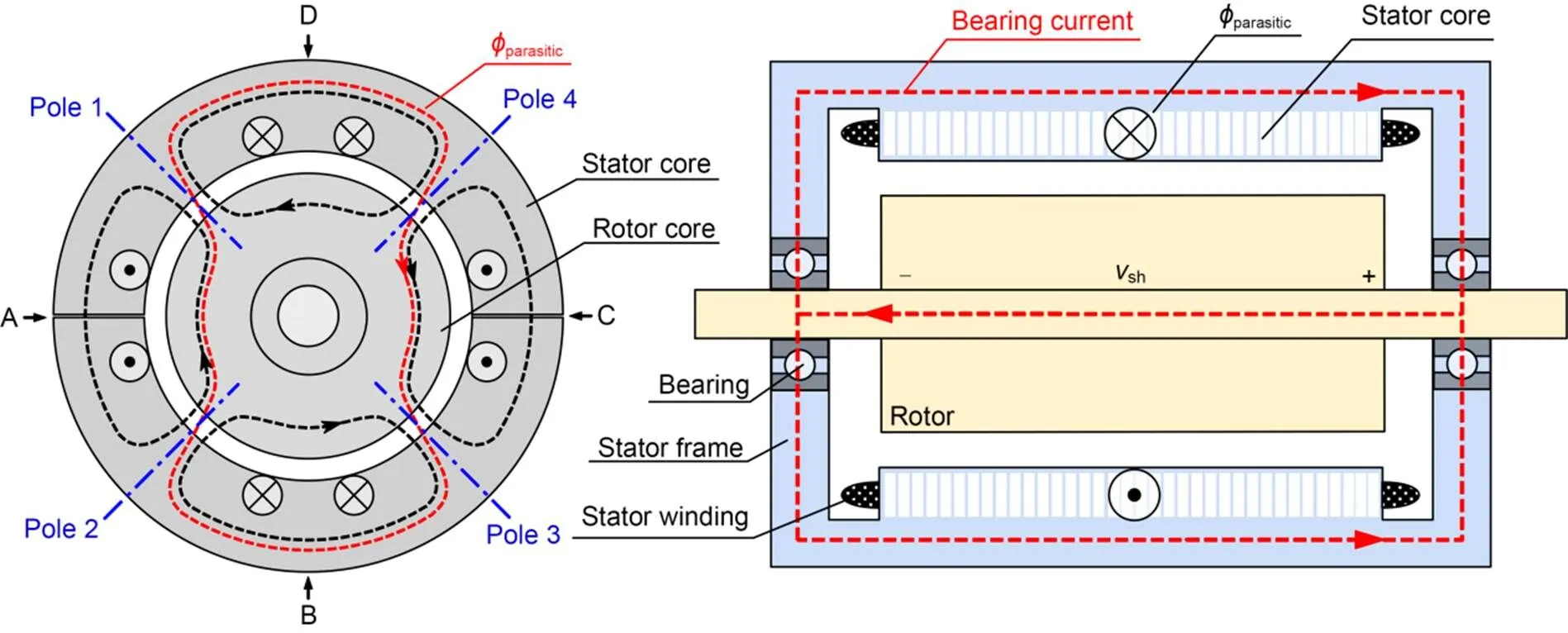
Fig. 1 Bearing currents due to magnetic asymmetries. vsh is the shaft voltage
In recent decades, pulse width modulation (PWM) inverters with high-performance semiconductor switching devices have been frequently used in modern electric vehicles to achieve variable speed control. However, electric motors operated by PWM inverters are subjected to high-frequency (HF) bearing currents that were not previously a problem. The phenomena of HF bearing currents were first explained and modeled (Chen SM et al., 1996; Chen ST et al., 1996; Chen and Lipo, 1998). The non-zero common mode (CM) voltage generated by the PWM inverters is regarded as the source, and the capacitive coupling paths consist of the stator winding-to-frame capacitancewf, rotor-to-frame capacitancerf, stator winding-to-rotor capacitancewr, and bearingsb. Four types of HF bearing currents can be distinguished: d/dbearing currents (whereis the voltage andis the time), electric discharge machining (EDM) bearing currents, circulating bearing currents, and rotor ground bearing currents (Fig. 2). Due to the presence of coupling capacitances, a voltage dropbacross the bearing which mirrors the CM voltage is generated. With an intact lubricating film, d/dbearing currents flow through the path of the "stator winding–rotor–bearing–stator frame." Whenbexceeds the breakdown voltage of the lubrication, therfdischarges over the shorted bearing, leading to EDM bearing currents. The HF ground current caused by thewfproduces a flux encircling the shaft, creating circulating bearing currents along the loop of the "stator frame–non drive end–shaft–drive end." Rotor ground bearing currents occur when the rotor is connected to the ground with a lower impedance path than the stator frame. In this case, part of the overall ground current flows through the "stator winding–stator frame–bearing–rotor–ground." A zero sequence equivalent circuit model for electrical analysis of EDM currents has been proposed and the related model parameter formulas derived (Busse et al., 1997a, 1997b, 1997c, 1997d, 1997e). With the calculated bearing current density, the electrical bearing life can be estimated (Busse et al., 1997a, 1997c). Muetze (2004) published a series of papers, including: a systematic summary of bearing currents generation theory, improved approaches for the calculation of related parameters (Muetze and Binder, 2007b), analytical calculation and measurement for EDM currents (Muetze, 2004), modeling and calculation of circulating bearing currents (Muetze and Binder, 2007a), guidelines for bearing currents assessment (Muetze and Binder, 2007c), and mitigation technique selection (Muetze and Binder, 2006). Industrial measurement techniques for HF bearing voltages and currents are now provided by various bearing companies. A simple but intrusive way to measure the bearing voltages involves the use of shaft brushes (AEGIS, 2007). SKF (2014) used an electrical discharge detector pen to count the number of discharges to estimate the extent and severity of the bearing defect. In addition, Rogowski coils are widely used to monitor ground currents associated with high d/d(ABB, 2021). A patented solution for bearing current protection was provided by AEGIS. This solution consists of a conductive ring mounted on the shaft, providing a low-impedance path to the ground for bearing currents, and is now used widely (Muetze and Oh, 2008a, 2008b). Recently, diagnostic methods based on artificial intelligence (AI) have attracted much attention (Cheng et al., 2020; Zhang et al., 2020; Shamsirband and Khansari, 2021). SKF (2019, 2022) used AI visual to differentiate electrical current damage from abrasive wear. Other measurement and mitigation techniques can be found in IEC60034-25 (IEC, 2014).
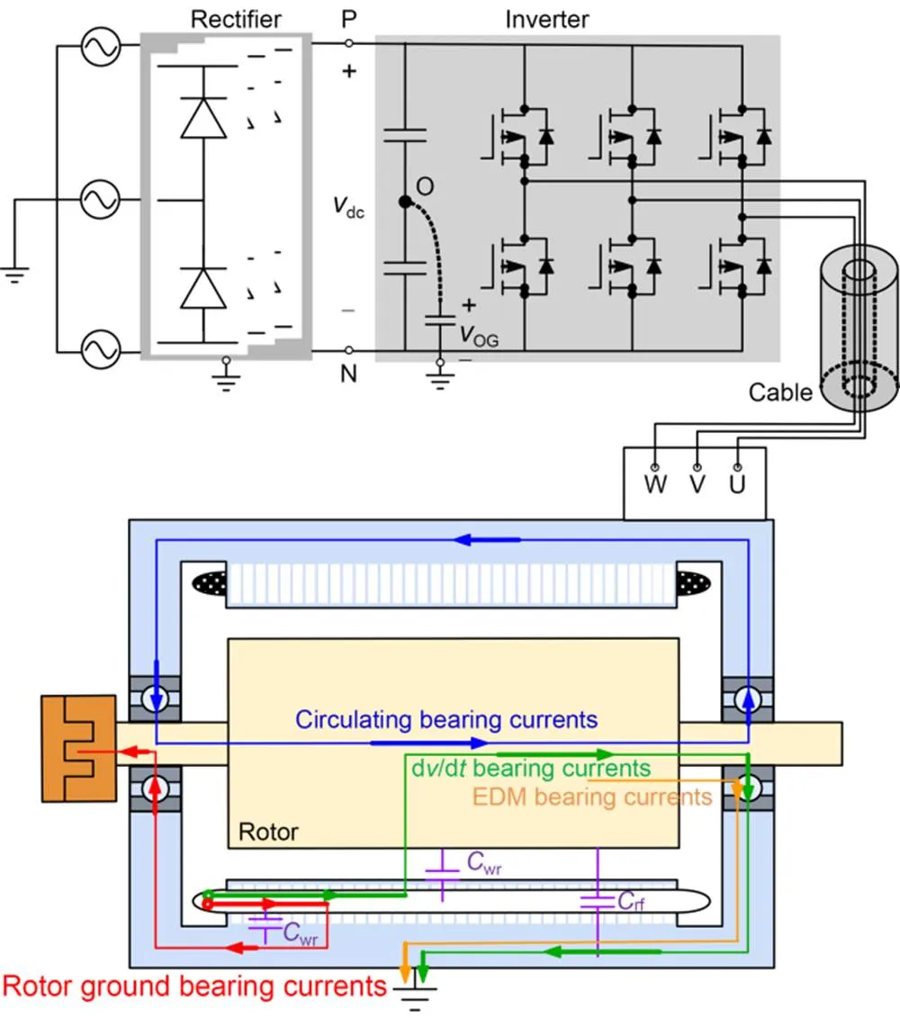
Fig. 2 Bearing currents due to inverter operation. vdc is the direct current (DC)-link voltage; vOG is the voltage of virtual neutral point O to ground. P and N are the positive and negative DC rails, respectively; U, V, and W represent the three inverter phases
The problem of electric currents passing through rolling bearings and causing damage in the contact area of rollers and inner/outer ring raceways is well-known, leading to a new kind of failure mode. The electric-related damage can be divided into five types: pitting, frosting, fluting, white etching cracks, and grease degradation (Boyanton and Hodges, 2002; Sunahara et al., 2011; Tischmacher and Gattermann, 2012a, 2012b; AEGIS, 2018; Plazenet and Boileau, 2021). Once the bearing voltage reaches a level sufficient to overcome the dielectric properties of the bearing grease, they arc through the motor's bearings, leaving small craters on the metallic surface, formed by the local melting of the metal due to the arc current. These pits have an average diameter of about 0.5 μm and can be seen using scanning electron microscopy (Fig. 3a) (AEGIS, 2018). The frosting consists of countless pits caused by frequent discharges, and appears as a grey discolored line around the bearing race. Fig. 3b shows an example of the frosting as seen under a microscope (AEGIS, 2018). Fluting is the most common pattern seen on visual inspection of the bearings, and is characterized by rolling axis paralleled and equally spaced flutes. The washboard-like ridges such as those shown in Fig. 3c (AEGIS, 2018) cause vibration and noise and indicate a catastrophic bearing failure. Meanwhile, bearing currents have been regarded as one of the factors inducing white etching cracks. A rolling contact fatigue mode will develop into irreversible brittle flaking, spalling, or radial cracking of bearing components, and is characterized by a wide subsurface network of cracks typically from 0.1 to 1.0 μm in width (Fig. 3d) (Plazenet and Boileau, 2021). In addition, the energy released by bearing current discharge events may cause grease degradation, which is a self-amplifying process (Tischmacher and Gattermann, 2012b). With a degraded lubrication film, the vibration level and frequencies increase (Tischmacher and Gattermann, 2012a), which further affects film thickness and the electrical field strength, increasing the number of voltage breakdowns in a certain period. As a result, corrugated patterns are formed, which in turn increase the vibration levels. Fig. 3e depicts the burnt grease (AEGIS, 2018).
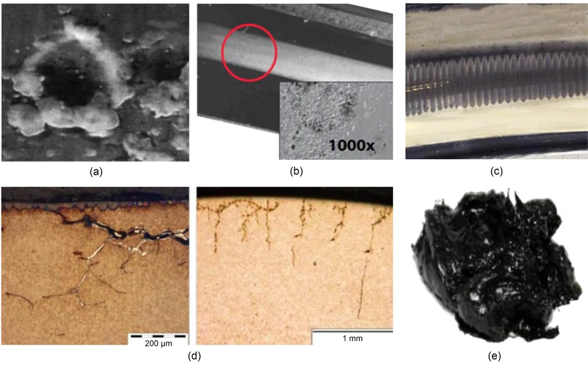
Fig. 3 Electrical bearing failure modes: (a) pitting; (b) frosting; (c) fluting; (d) white etching cracks; (e) grease degradation
Over the years, electrical bearing failures are more likely to occur in rolling mills because of their poor working conditions, including heavy impact, excessive radial and axial loads, and high temperature. However, with the development of rail transportation, bearing failures in railway traction motors have been widely reported due to long operation times and complex and harsh environments. Fig. 4 shows inverter-induced bearing damage in railway vehicles. Since the assembly and disassembly of bearings are complicated, the bearing failures in a running train are difficult to detect in the early stages using traditional fault diagnostic techniques. This not only adds to the cost of bearing replacement, but also poses potential threats to the safe and stable operation of the traction system. The consequences of bearing damage range from train delay and suspension to train brake failure and accidents. Unlike in other AC motor applications, inverter-induced electrical erosion in rail transportation has the following special features: (1) It has a high CM component in inverter output voltages with high d/d. Considering the high voltage and large current in practical onboard traction converters, the switching frequency is limited to several hundred Hz to reduce switching loss, which is close to the output frequency of the converter in the high-speed region. Thus, synchronized modulation strategies and a six-step operation are adopted (Zhao et al., 2020), which generate high d/dstepwise CM voltage between the motor neutral and its stator frame. (2) It has a complicated grounding configuration. In ideal cases, the stator frame is grounded to earth with a low-impedance cable, and the rotor is not grounded. However, in railway vehicles, the impedance of the protective earth return path is non-negligible, and includes the "stator frame–bogie–vehicle body–protective resistor–return busbar–grounding brushes–wheelset contact." Additionally, for railway vehicles operating at low speed, the rotor is grounded via the gearbox to earth potential, which forms a lower impedance path than the grounding of the stator frame.
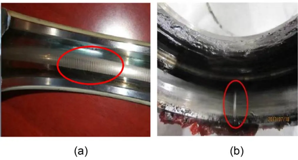
Fig. 4 Bearing failures in metro vehicles (a) and electric multiple units (EMU) trains (b)
In this paper, we provide a review of electrical bearing current phenomena in railway vehicles. In the following sections, the mechanisms that generate bearing currents, classified into four categories, are introduced first. Then, the established models for analyzing bearing currents are reviewed, including railway vehicle system configurations and the related impedance determination of the coupling path. In addition, the strategies frequently used in the industry for bearing protection are summarized, and a typical solution used to suppress electrical bearing failures in railway vehicles is described. Finally, a case study is presented to illustrate the research procedure for the systematic investigation of inverter-induced bearing currents in railway vehicles.
2 Analysis and modeling of bearing currents
2.1 Classification of bearing currents
The origin of the bearing current phenomena is the CM voltagecm, which is defined by the arithmetic mean of the line-to-ground voltages (Eq. (1)). Due to the discrete switching states in PWM, the sum of three output voltages is not equal to zero. The HF components of this voltage interact with the parasitic capacitances of the motor, exciting the inverter-induced bearing currents, which can be further classified into non-circulating and circulating bearing currents by their flow paths.
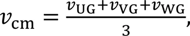
whereUG,VG, andWGare the voltages of the three inverter phases U, V, and W to ground, respectively.
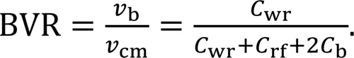
The non-circulating type of bearing currents includes the d/d, EDM, and rotor ground bearing currents. At elevated motor speed, the lubricating film of the bearing has insulating properties, and the bearing acts as a capacitorb. When the rotor is not grounded, the CM voltage generates bearing voltagebacross the bearing due to the voltage divider of the motor parasitic capacitances. The ratio betweenbandcmis named the bearing voltage ratio (BVR), and can be calculated as follows:
The d/dbearing currents can be capacitive or conductive (Bhattacharya et al., 1999). At each switching instant, the charge/discharge capacitive currents flow through the path of the "stator winding–rotor–bearing–stator frame," and their magnitudes are given by Eq. (3). However, at low motor speed, the lubrication film is bridged by metallic contact. In this case, the bearing is an ohmic resistance, and conductive currents are generated. In the literature, the effect of this kind of bearing current is neglected because of its much smaller amplitude (typically 5–200 mA) than other types of bearing currents (Muetze and Binder, 2007a).
Rotor ground bearing currents arise when the rotor-to-ground impedance is lower than the stator-to-ground impedance (Muetze, 2004; Muetze and Binder, 2006). In this case, the bearing voltage is reconfigured, which results in considerable rotor ground bearing currentsb,rgflowing through "stator winding–stator frame–bearing–rotor–ground."b,rgmay reach considerable magnitudes (1–35 A) and is harmful to the bearings.
Unlike the non-circulating bearing currents, the generation of a circulating current is due to both inductive coupling and capacitive coupling. The steep edges of the HF CM voltage at the motor terminals couple with the parasitic capacitancewf, generating the HF CM currentcmflowing through the stator core. This causes an alternating fluxcirencircling the shaft, and inducing a voltageshalong the motor shaft. Ifshis capable of puncturing the bearing lubrication film, the HF bearing currents (0.5–20 A) circulate in the loop "stator frame–non drive end–shaft–drive end." This type of bearing current mirrorscmand flows in opposite directions in two bearings (Chen and Lipo, 1998; Muetze and Binder, 2007b).
Based on the above analysis, for large motors in railway vehicles, the rotor ground bearing currents and circulating bearing currents are major contributors to inverter-induced bearing failures. According to experimental results (Muetze and Binder, 2006, 2007a), a proper thickness of insulation can reduce the HF circulating bearing currents to less than 40% of the values associated with non-insulated bearings. Therefore, the rotor ground bearing currents are the main cause of bearing electrical erosion in railway vehicles.
2.2 Modeling of non-circulating bearing currents
Chen ST et al. (1996) first proposed the equivalent lumped parameter circuit model of inverter-induced bearing currents. On the basis of the transmission line theory, an equivalent lumped parameter π- network is used for a simplified analysis of the parasitic coupling phenomenon. However, the model parameters need to be identified by matching simulation results with experimental measurements. For a more comprehensive understanding of the phenomena, Busse et al. (1997a, 1997b, 1997c, 1997d, 1997e) proposed the resistance-inductance-capacitance (RLC) equivalent circuit model. The model provides an efficient tool for the analysis of system parameters, such as the inverter output CM voltage, series and parallel impedance elements (seriesandparallel, e.g. long cables, CM chokes, transformers, and line reactors), the stator windings zero-sequence impedance (0), and their influence on bearing currents. In addition, Muetze (2004) used a controllable switch to model the breakdown process of the lubrication film and investigated the inaccuracy of the measurable and real bearing currents. To discuss the effect caused by the presence of the rotor grounding path, the bearing current model was extended by adding the frame-to-ground impedancefgand rotor-to-ground impedancerg(Guttowski et al., 2006; Liu et al., 2015a). Based on the above analysis, a model of non-circulating bearing currents is depicted in Fig. 5.
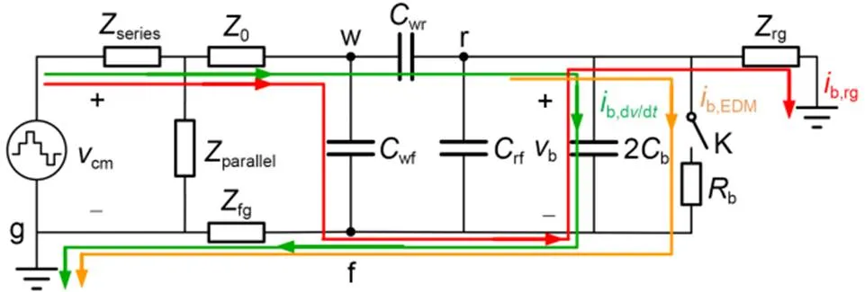
Fig. 5 Equivalent circuit model for non-circulating bearing currents
However, the system configurations for rail transportation are more complicated (Fig. 6) (Zhang, 2008; Yan et al., 2019). For metro vehicles, the positive supply rail of the inverter is connected to 1500 V DC, and the negative one is connected to the return bus bar. The bus bar is further grounded to the wheel with earth return devices, which provide return paths for both working earthing and protective earthing. The protective earthing connection for traction motors includes "motor frame–bogie chassis–vehicle body–protective resistor–bus bar." For EMU trains, the system is powered by 25 kV/50 Hz, and the supply voltage for the single-phase rectifier is lowered to 900 V with a step-down transformer. Unlike metro vehicles, the earth return devices are installed at the bogie chassis. Thus, the tractive current returns to the ground via "vehicle body–bogie chassis–earth return devices," and the working earthing for traction motors is simplified to "motor frame–bogie chassis–earth return devices." In addition, for railway vehicles, the rotor is grounded with a low-impedance path consisting of "rotor–shaft coupling–gearbox–wheel." Therefore, the bearing currents have two coupling paths. The motor frame groun ding impedance of metro vehicles is higher than that of EMU trains, which means metro vehicles are more prone to bearing electric erosion caused by rotor ground bearing currents.
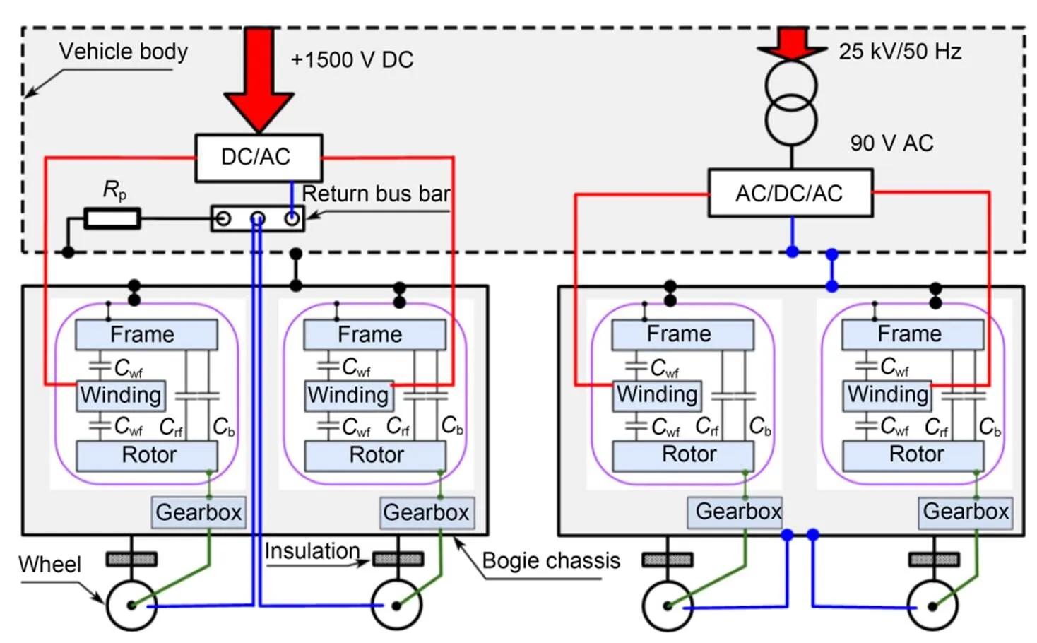
Fig. 6 System configurations for railway vehicles
2.3 Determination of coupling capacitances
For HF components of CM voltage less than 100 kHz, the coupling paths are simplified to be pure capacitive, including three equivalent parasitic capacitances and two bearing capacitances. Theoretical methods for calculating equivalent capacitances can be classified as analytical methods (Busse et al., 1997d; Muetze, 2004; Liu et al., 2014a; Wang et al., 2015) or finite element methods (FEMs) (Magdun et al., 2010b; Liu et al., 2014a, 2015b). A schematic of a stator slot segment is shown in Fig. 7, which illustrates the parameters used in an analytical method.
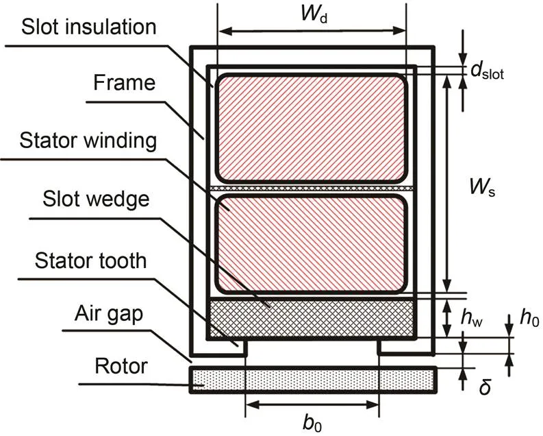
Fig. 7 Schematic of a stator slot segment used in an analytical method
Busse et al. (1997d) first introduced the analytical calculation ofwf, which consists ofsparallel capacitors. Each slot is modeled as a rectangular conductor, with lengthFe, widthd, and depths. The dielectric material separates the stator winding and frame byslotwith a relative permittivity ofr1. The effect of the winding irregular surface is considered by the factorc(Muetze, 2004), which is in the order of 0.8 to 1, and set as 1 in this paper, for simplicity. With these assumptions,wfis calculated as
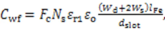
where the permittivity of the vacuum0=8.854×e-12F/m. Additionally, Adabi et al. (2010) considered the stator windings-to-stator teeth equivalent capacitance, which makes the results more accurate.
The capacitancerf1is considered as that of a cylindrical air-insulated capacitor between the rotor surface and stator iron (Busse et al., 1997d). On this basis, the Carter coefficientcis introduced to account for the influence of the stator slot openings. Since the air gap lengthis much smaller than the outer diameter of the rotorre, the analytical expression ofrf1is further simplified as (Muetze, 2004):
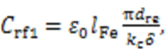
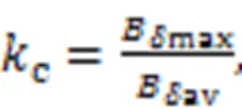
whereBavis the average magnetic field density in the air gap along the circumference, andBmaxis the maximum magnetic field density in the air gap. Generally,cis slightly greater than 1, and is set to 1 in this paper, for simplicity.
The analytical calculation of stator winding-to-rotor capacitancewrwas first proposed by Busse et al. (1997d).wrconsists ofssets of parallel plate capacitors formed by the stator coils in slots and the rotor surface, with widthd, lengthFe, and a dielectric distance of. However, the method neglects the effect of the slot wedge and stator slot opening. Subsequently,wris modeled as a series connection of the capacitance of the air gapand the slot opening0, and the capacitance of the slot wedgewand the slot insulationslot(Muetze, 2004), which can be calculated as
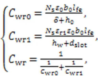
where0is the width of the stator tooth. For more accuracy, the capacitance formed by stator windings, stator teeth, and rotor surface is considered (Adabi et al., 2010).
Magdun et al. (2010b) first presented the FEM calculation of motor capacitances. Based on the electric field energy calculation, the capacitances are calculated using a 2D solid conductor model. Althoughrf1is correctly calculated, the distribution of the stator windings in the slot and their end effects are not considered. To this end, the scattered line model along with the 3D FEM was introduced to increase the computational accuracy (Magdun et al., 2010b; Liu et al., 2014a, 2015b).
Busse et al. (1997d) first proposed the theoretical calculation of bearing capacitance, which comprisesbparallel sphere capacitors formed by the ball element sphere (ball) and raceway sphere (ball+g):
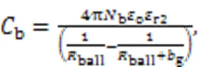
wherer2is the relative permittivity of the lubrication film.
However, this methodology will result in significant inaccuracy of the capacitance value due to the inappropriate simplification of the sphere capacitor. Combined with elastic deformation and fluid mechanics analysis, the formulas of the grease film thicknessHertzand the Hertzian contact areaHertzare obtained, then the bearing capacitanceHzcan be evaluated by Eq. (10) (Muetze, 2004). To improve the cxalculation accuracy, the electrical coupling between the ball elements and inner/outer ring is considered byair(Fig. 8) (Magdun and Binder, 2009; Liu et al., 2014b).
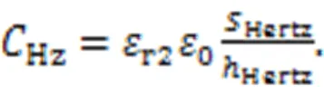
Additionally, a novel approach to calculating the equivalent bearing capacitance was proposed by Liu et al. (2017). On the basis of the elastohydrodynamic lubrication analysis, hHertz can be determined. Thus, 3D bearing models can then be established in ANSYS Maxwell finite element analysis software and the capacitance can be obtained.
3 Techniques for suppressing bearing currents
The main purpose of investigating bearing current phenomena is to prolong the bearing life and achieve long-term reliability. Numerous strategies have been put forward to suppress bearing currents, and according to their functions, these methodologies can be categorized into two groups.
The first group includes inverter-side mitigation strategies that target the HF CM voltage caused by PWM inverters. The schematic diagram of a typical converter-motor system is shown in Fig. 2. The calculation of CM voltage can be written as Eq. (11), which includes two parts.
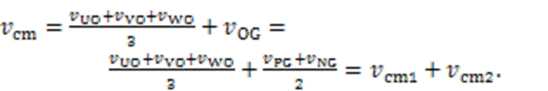
Under the assumption ofOG=0, the case is simplified to a three-phase two-level inverter-motor system and the CM voltage levels include ±dc/6 and ±dc/2, forming a four-level staircase waveform. The analytical harmonic solution forcm1with double-edge naturally sampled PWM can be described as (Holmes and Lipo, 2003):
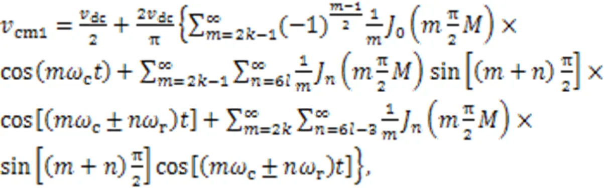
whereis the modulation index,cis the carrier wave angular frequency,ris the fundamental wave angular frequency, andJis the Bessel function of order. From Eq. (12),cm1consists of odd carrier harmonics and sideband harmonics with even combinations of±, while the fundamental component and even carrier harmonics are eliminated. For the second partcm2,PGandNGare determined by the conducting diodes of the input rectifier. The sum of thePGandNGoscillates with a frequency equal to three times the frequency of the source voltage (Tischmacher et al., 2015; Furtmann et al., 2016). The simulation waveforms ofcm,cm1, andcm2and their respective fast Fourier transform (FFT) spectra are depicted in Fig. 9.
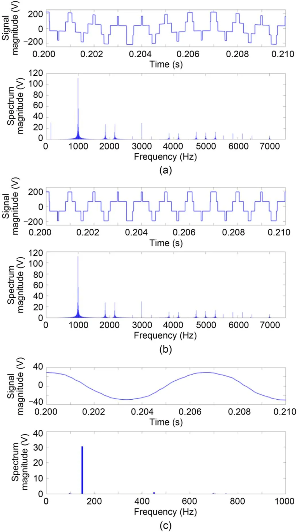
Fig. 9 Simulation waveforms of vcm (a), vcm1 (b), and vcm2 (c) and their respective FFT spectra (sinusoidal pulse width modulation, fc=1 kHz)
From the above analysis ofcm, the most direct approach for bearing current mitigation techniques is to lower the switching frequency with limited control performance (Muetze and Binder, 2007d), which is not recommended. Filter techniques are used to reduce the HF CM voltage at the motor terminals, such that the bearing voltage is kept in check (Hyypio, 2005; Akagi and Tamura, 2006; Hedayati et al., 2013). Without additional hardware costs, the CM voltage is limited by advanced PWM control techniques (Un and Hava, 2009; Han et al., 2019). Compared with the conventional modulation techniques such as space vector PWM and discontinuous PWM, the peak amplitude of CM voltages generated by the active zero state PWM and near-state PWM is reduced from ±dc/2 to ±dc/6. On the other hand, the CM voltage can be naturally suppressed by multilevel inverters (Wang, 2000; Zhang et al., 2000). In addition, Muetze and Sullivan (2011) suppressed CM currents using magnetic rings that have an easy-to-install design and a simple structure. Experimental results show that these low-cost CM chokes can effectively reduce the circulating bearing currents and rotor ground bearing currents, while having little effect on the EDM bearing currents.
The second group consists of mitigation strategies in the motor. The most commonly used method is to break the HF bearing current loops with insulated/hybrid/full ceramic bearings (Muetze and Binder, 2007c; Plazenet et al., 2018). Insulated bearings are steel bearings with an insulating aluminum oxide layer deposited on the outer surface of the outer bearing ring. These bearings already have been used to suppress classical, circulating, and rotor ground bearing currents. For small motors that suffer from EDM bearing currents, hybrid bearings consisting of steel bearing rings and ceramic bearing rolls/balls are recommended. Although hybrid bearings can suppress all kinds of bearing currents completely, less expensive insulated bearings are more commonly used since they are sufficient to suppress the bearing currents for large machines (Muetze and Binder, 2006). Full ceramic bearings have inner/outer races and balls made of either silicon nitride, zirconium oxide, or silicon carbide. These are designed for applications operating in extreme special environments where conventional bearings are not suitable, such as vacuum environments and semiconductor manufacturing. Another typical approach is to use the shaft grounding mechanism to ensure a low potential on the motor shaft. In industry, many trouble-free AC motor applications are protected against bearing voltages by means of specially designed brushes, which provide a low-impedance path to ground for the harmful bearing currents. Based on similar principles, an alternative brush concept with less maintenance than traditional grounding brushes is emerging in the industry (Muetze and Oh, 2008a, 2008b, 2010). Making use of conductive microfibers, this kind of brush has ultralow friction and is very robust toward contamination. Besides, it is particularly suitable for use with EDM and circulating bearing currents. Although being the opposite of insulating methods, greases with enhanced conductivity are effective in preventing fluting (Suzumura, 2016). However, there is still a lack of industrial lubricants with superior conductivities and outstanding lubricities. Furthermore, Busse et al. (1997d) proposed a modified induction motor by mounting a Faraday shield in the air gap between the stator and rotor. Experimental results prove that the electrostatic shielded induction motor solves the inverter-induced bearing voltage with increased eddy current loss. Likewise, grounded slot wedges or electrodes can be constructed in the stator slots to suppress EDM bearing currents using the electrostatic shield principle (Ferreira et al., 2012; Bai et al., 2015; Vostrov et al., 2021). In addition, recent studies addressing the problem by modifying the design of the electric machine provide a different perspective (Yea and Han, 2020; Berhausen and Jarek, 2022).
For railway vehicles, the problems of bearing currents are commonly solved by the bearing insulation and shaft grounding mechanism because of their technological maturity and ease of implementation. In addition, inspired by the mechanism of generation of rotor ground bearing currents, researchers suggest this kind of bearing current can be limited by optimizing the grounding configuration (Liu et al., 2015a; Yan et al., 2019; Chen, 2021; Luo, 2021). Taking metro vehicles as an example, the commonly used topology is shown in Fig. 10, where the vehicle body is connected to the return bus bar with a protective resistor. Then, the bus bar is grounded to wheels via the earth return devices. Accordingly, the overall protective earthing loop is so long that the equivalent grounding impedance at the motor frame has an order of magnitude similar to that at the motor shaft, which means considerable HF grounding currents will flow across the bearing. To reduce the cable length between the vehicle body and earthing device, a protective resistor is installed at each bogie chassis for each car body, which is referred to as the "double-resistor scheme" (Fig. 10). In this case, the vehicle body is directly grounded with the protective resistor above the bogie chassis, and the grounding impedancefgis significantly decreased. Consequently, HF motor grounding currents are more likely to flow back to earth throughfgcompared withrg, which suppresses the bearing currents.
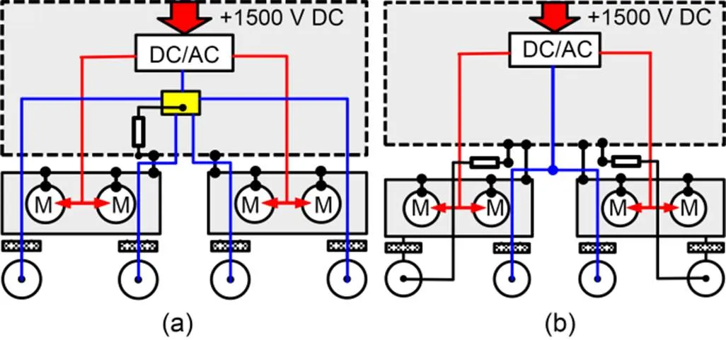
Fig. 10 Grounding configuration before (a) and after (b) optimization
4 Case example
Here, we describe a case example to illustrate the research procedure for the systematic investigation of inverter-induced bearing currents in railway vehicles. It involves an inverter-driven 190-kW four-pole squirrel cage induction motor with insulated bearings, used in a metro project.
First, the mechanism of generation of the bearing currents is identified. For metro vehicles operating at low speed, a lubrication film in the gearbox is not formed. The rotor is grounded to the axle via a non-insulated coupling and a short-circuited gearbox. In this case, rotor ground bearing currents are the main cause of bearing electric erosion. At elevated running speed, a lubrication film with small capacitance on the gear meshing surface is formed, which blocks the rotor grounding path. A four-level staircase bearing voltage waveform along with EDM currents is generated. For a 190-kW motor, such EDM bearing currents are not likely to cause much bearing damage, but the endangerment of bearings due to rotor ground bearing currents at low speed should be investigated.

Fig. 11 Equivalent circuit model of metro traction system
Next, the equivalent circuit model of the metro traction system is proposed (Fig. 11). The related parameters are explained in Table 1. The CM voltage generated by the traction inverter couples with the motor parasitic capacitances and system earthing impedances, forming a current flowing through the bearing.
Table 1 Explanation of parameters in the equivalent circuit model
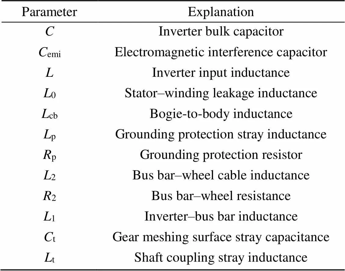
ParameterExplanation CInverter bulk capacitor CemiElectromagnetic interference capacitor LInverter input inductance L0Stator–winding leakage inductance LcbBogie-to-body inductance LpGrounding protection stray inductance RpGrounding protection resistor L2Bus bar–wheel cable inductance R2Bus bar–wheel resistance L1Inverter–bus bar inductance CtGear meshing surface stray capacitance LtShaft coupling stray inductance
Then, related parameters are determined to predict the bearing voltage in such a system configuration. Through field research, the switching frequency of the traction inverter is in the range of 400 to 1500 Hz, and is set to 1000 Hz in the simulation. The electromagnetic interference (EMI) capacitor is equal to 1 μF and the cable inductance2is set as 0.5 μH.0can be extracted by the port impedance test results measured by the impedance analyzer (Magdun and Binder, 2014; Zhao et al., 2021), which is 48.1 μH.
The coupling capacitances in the motors are analytically calculated with some simplification based on Eqs. (5)–(8). Forwf, we assume the slots are to be filled with stator windings and slot insulation, and the surface of the windings is regular (c=1).wris formed as a series connection of capacitors, including the slot insulation, slot wedge, and air. For simplification, the permittivity of slot insulation is set as the same as that of the slot wedge. In this way, the analytical value ofwrcan be calculated using Eq. (8). Note that, for motors with insulated bearings, the capacitance of the insulating layerinsshould be included in the calculation ofrfin the static state. In addition, the 3D model of the structure of stator and rotor is established (Fig. 12). The theoretical results are listed in Table 2 (Zhou et al., 2022).
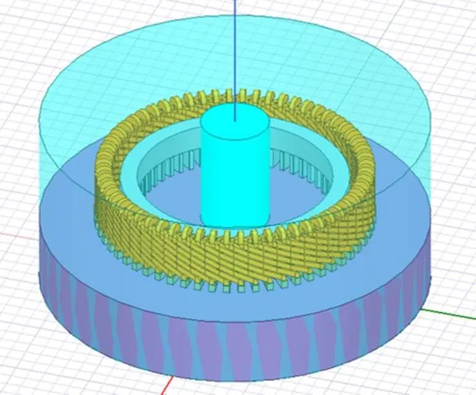
Fig. 12 3D model of the structure of the stator and rotor
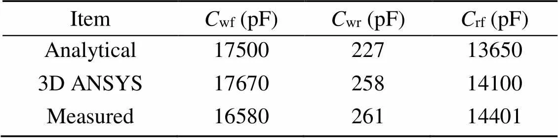
Table 2 Calculated motor equivalent capacitances
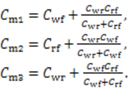
In practice, the motor capacitances are measured using the method proposed by Liu et al. (2014a) (Fig. 13). For insulated motors, the measurement comprises the following steps: (1) keep the motor still; (2) use the inductance-capacitance-resistance (LCR) meter and three different configurations to derivem1,m2, andm3; (3) calculatewf,wr, andrfaccording to Eq. (13). The experimental results are listed in Table 2.
Compared with the measured values of motor capacitances, the analytical result ofwfis larger due to the assumption that the slots are full, which overestimatessin Eq. (5), whilewris smaller due to neglecting the effect of stator winding ends. The latter problem is dealt with by the 3D ANSYS, and the calculated capacitance agrees well with the measured value. According to Muetze (2004) and Liu et al. (2017), the analytical result of bearing capacitance is 152 pF and the measured value is 171 pF. In comparison, the analytical result is smaller becauseHertzis smaller than the actual area, and the electrical coupling air capacitanceairis neglected.
Fig. 13 Diagram of capacitance measurement
To verify the correctness of the proposed equivalent circuit for the prediction of the bearing voltages in a metro vehicle traction system, simulations have been done in the MATLAB/Simulink environment and compared with the measured waveform of a metro project (Fig. 14). The peak bearing voltage is beyond 100 V in the starting and braking stages, and the staircase amplitude is much smaller at elevated speed. The four-level staircase waveform is not apparent for low-voltage utilization, and a reversed bearing voltage is observed due to the film discharge and switching state change. At low speed, the overlap of transient response makes the bearing voltage peak amplitude variable. The simulation waveforms of bearing voltage are shown in Fig. 15. Neglecting the film discharges, the staircase waveform is consistent with the experimental result. However, the voltage at low speed is not well predicted because the rising time of insulated gate bipolar transistors and the accuracy of parasitic parameters have great impacts on its waveform. With the equivalent circuit, the mechanism of generation and waveform characteristics of the bearing voltage are revealed.
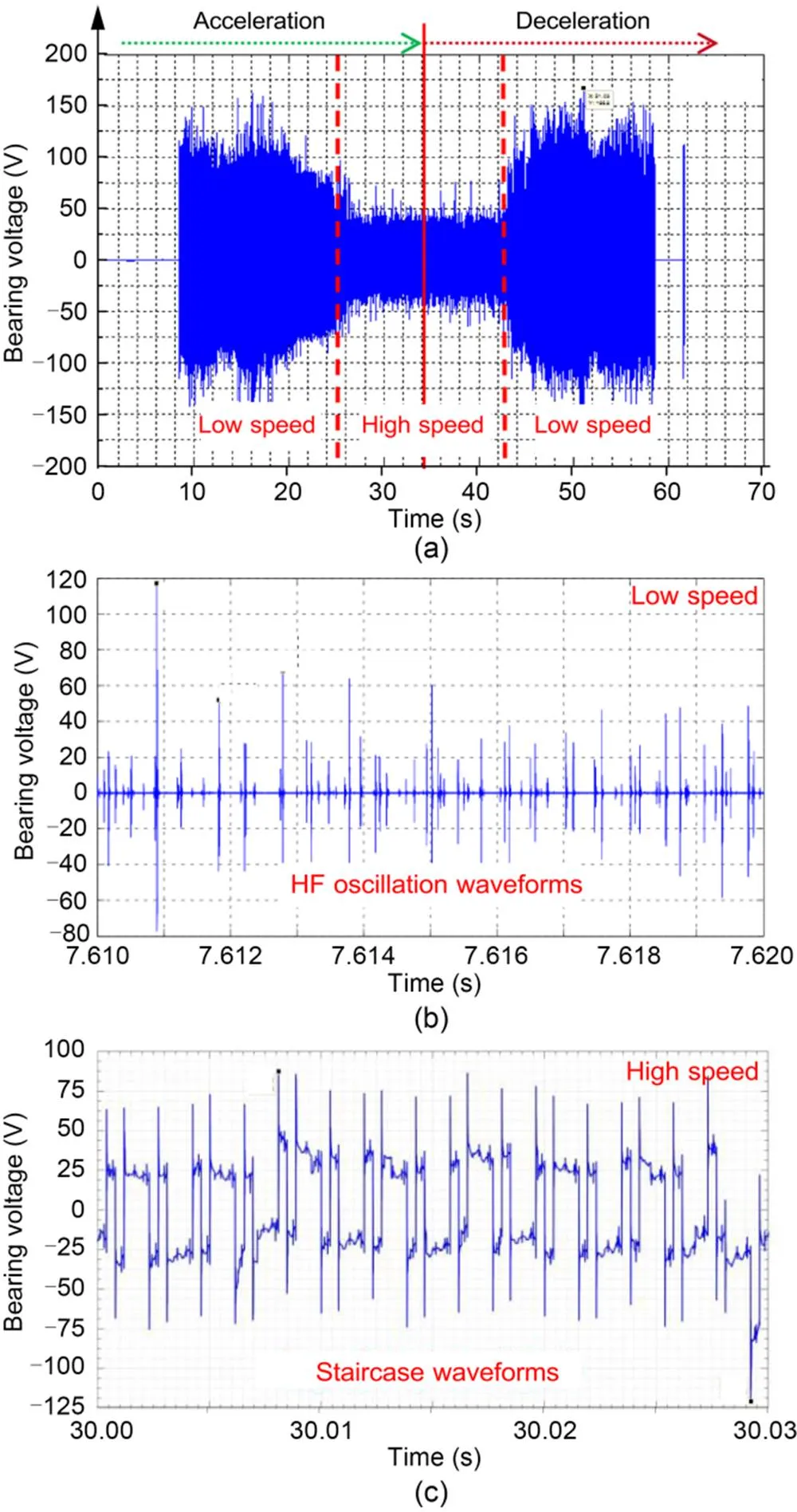
Fig. 14 Measured bearing voltage waveforms of a metro project with a single-resistor scheme: (a) overall waveform; (b) low-speed waveform; (c) high-speed waveform
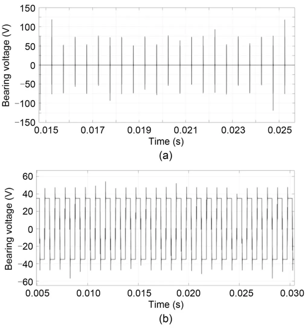
Fig. 15 Simulated bearing voltage waveform: (a) low speed; (b) high speed
Finally, mitigation techniques such as shaft groun ding rings and grounding configuration optimization were applied to the metro projects to validate their effectiveness. With the use of the shaft grounding ring, the motor frame and shaft are short-circuited, and the bearing capacitance is isolated. The bearing voltage is significantly suppressed to 15 V (Fig. 16). However, the introduction of grounding rings may cause reflux through the vehicle body and gear meshing surface, which further leads to electromagnetic interference and gearbox damage. In addition, the service life and maintenance requirements are yet to be determined.
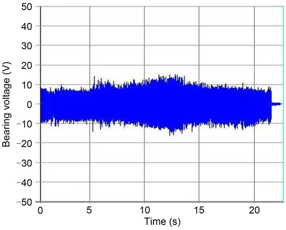
Fig. 16 Bearing voltage waveform with the use of shaft grounding rings
With improved grounding configurations, the value of equivalent grounding inductance2is decreased, and more HF currents will flow through this path rather than across the bearing. Fig. 17 shows the test results using the double-resistor scheme for a domestic metro project. Compared with Fig. 14, the use of the double-resistor scheme appears to effectively reduce the bearing voltage.
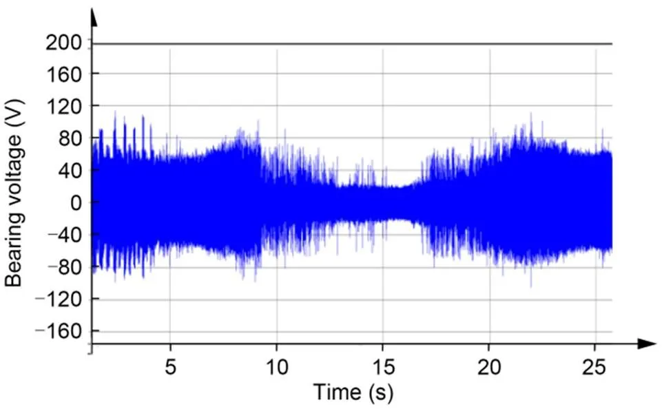
Fig. 17 Measured bearing voltage waveform of a metro project with the double-resistor scheme
5 Conclusions
The premature electrical failure of bearings has become a critical issue that has for decades restricted the lifetime of electric motor-based traction systems. In this study, an overview of electrical bearing failures in rail transportation has been presented. Related facets such as CM voltages, bearing electrical failure modes, generation and composition of bearing voltages and currents, modeling of bearing currents, and determination of coupling capacitances have been discussed to obtain a comprehensive and systematic perspective on the phenomena. On this basis, feasible ways to solve the problem are summarized, and a case study is presented to illustrate the research procedure recommended for the systematic investigation of inverter-induced bearing currents in rail transportation.
Despite the significant progress made in this area, further study is required in the following pertinent directions:
(1) A generalized prediction model for bearing currents. In this review, four typical bearing current modes are analyzed in simplified inverter-motor systems. However, the overall electrical system topology in practical applications is not consistent. For instance, the direct grounding of the motor frame and inverter is not achievable in metro vehicles, which complicates the composition of bearing currents. In these complex motor systems, more research is needed to predict the bearing currents quantitatively.
(2) Additional low-cost industrial bearing protection techniques. In Section 3, a summary of numerous bearing current mitigation techniques has been presented. Given their cost and reliability, it is still challenging to adopt these techniques for industrial use. Recent developments in lubrication materials with new electrical properties offer a broader perspective for possible solutions to bearing currents.
This work is supported by the National Key R&D Program of China (No. 2018YFB1201804) and the National Natural Science Foundation of China (Nos. 52293424, 51827810, and 51977192).
Yao LI conducted the literature survey and wrote the first draft of the manuscript. Yongjian ZHI, Zifan GAO, Jien MA, and Jian ZHANG assisted with the literature survey and processed the experimental data. Lin QIU and Youtong FANG put forward the original idea of the proposed framework and supervised the research activities.
Yao LI, Lin QIU, Yongjian ZHI, Zifan GAO, Jien MA, Jian ZHANG, and Youtong FANG declare that they have no conflict of interest.
ABB, 2021. Rogowski Coil Current Sensors for Arc Flash Detection. ABB Review. https://new.abb.com/news/detail/78554/rogo-wski-coil-current-sensors-for-arc-flash-detection
Adabi J, Zare F, Ghosh A, et al., 2010. Calculations of capacitive couplings in induction generators to analyse shaft voltage., 3(3):379-390. https://doi.org/10.1049/iet-pel.2008.0332
AEGIS, 2007. Shaft Grounding Rings for Low Voltage Motors. https://www.est-aegis.com/product/sgr/
AEGIS, 2018. Bearing Protection Handbook: Best Practices for Bearing Protection in New and Repaired Motors, Testing In-Service Motors, and Inspecting Damaged Motor Bearings. https://www.morganadvancedmaterials.com/media/7645/aegis-bearing-protection.pdf
Akagi H, Tamura S, 2006. A passive EMI filter for eliminating both bearing current and ground leakage current from an inverter-driven motor., 21(5):1459-1469. https://doi.org/10.1109/TPEL.2006.880239
Alger PL, Samson HW, 1924. Shaft currents in electric machines., XLIII:235-245. https://doi.org/10.1109/T-AIEE.1924.5060981
Ammann C, Reichert K, Joho R, et al., 1988. Shaft voltages in generators with static excitation systems-problems and solution., 3(2):409-419. https://doi.org/10.1109/60.4749
Bai BD, Wang Y, Wang XC, 2015. Suppression for discharging bearing current in variable-frequency motors based on electromagnetic shielding slot wedge., 51(11):8109404. https://doi.org/10.1109/TMAG.2015.2439961
Berhausen S, Jarek T, 2022. Analysis of impact of design solutions of an electric machine with permanent magnets for bearing voltages with inverter power supply., 15(12):4475. https://doi.org/10.3390/en15124475
Bhattacharya S, Resta L, Divan DM, et al., 1999. Experimental comparison of motor bearing currents with PWM hard- and soft-switched voltage-source inverters., 14(3):552-562. https://doi.org/10.1109/63.761699
Bonnett AH, Yung C, 2006. A construction, performance and reliability comparison for pre-EPAct, EPAct and premium-efficient motors. Record of Conference Papers– IEEE Industry Applications Society 53rd Annual Petroleum and Chemical Industry Conference. https://doi.org/10.1109/PCICON.2006.359691
Boyanton HE, Hodges G, 2002. Bearing fluting [motors]., 8(5):53-57. https://doi.org/10.1109/MIA.2002.1028391
Boyd J, Kaufman HN, 1958. The causes and control of electrical currents in bearings., 2(6):28-35.
Buckley GW, Corkins RJ, Stephens RN, 1988. The importance of grounding brushes to the safe operation of large turbine generators., 3(3):607-612. https://doi.org/10.1109/60.8075
Busse DF, Erdman JM, Kerkman RJ, et al., 1997a. Bearing currents and their relationship to PWM drives., 12(2):243-252. https://doi.org/10.1109/63.558735
Busse DF, Erdman JM, Kerkman RJ, et al., 1997b. Characteristics of shaft voltage and bearing currents., 3(6):21-32. https://doi.org/10.1109/2943.628116
Busse DF, Erdman JM, Kerkman RJ, et al., 1997c. The effects of PWM voltage source inverters on the mechanical performance of rolling bearings., 33(2):567-576. https://doi.org/10.1109/28.568024
Busse DF, Erdman JM, Kerkman RJ, et al., 1997d. System electrical parameters and their effects on bearing currents., 33(2):577-584. https://doi.org/10.1109/28.568025
Busse DF, Erdman JM, Kerkman RJ, et al., 1997e. An evaluation of the electrostatic shielded induction motor: a solution for rotor shaft voltage buildup and bearing current., 33(6):1563-1570. https://doi.org/10.1109/28.649969
Chen SM, Lipo TA, Fitzgerald D, 1996. Source of induction motor bearing currents caused by PWM inverters., 11(1):25-32. https://doi.org/10.1109/60.486572
Chen ST, Lipo TA, 1998. Circulating type motor bearing current in inverter drives., 4(1):32-38. https://doi.org/10.1109/2943.644884
Chen ST, Lipo TA, Fitzgerald D, 1996. Modeling of motor bearing currents in PWM inverter drives., 32(6):1365-1370. https://doi.org/10.1109/28.556640
Chen ZW, 2021. Comparative Study of Grounding Reflux Schemes for Metro Vehicles. MS Thesis, Beijing Jiaotong University, Beijing, China(in Chinese).
Cheng ZL, Zhou WH, Ding Z, et al., 2020. Estimation of spatiotemporal response of rooted soil using a machine learning approach., 21(6):462-477. https://doi.org/10.1631/jzus.A1900555
Costello MJ, 1993. Shaft voltages and rotating machinery., 29(2):419-426. https://doi.org/10.1109/28.216553
Ferreira FJTE, Cistelecan MV, De Almeida AT, 2012. Evaluation of slot-embedded partial electrostatic shield for high-frequency bearing current mitigation in inverter-fed induction motors., 27(2):382-390. https://doi.org/10.1109/TEC.2012.2187452
Fleishmann L, 1910. Currents in bearings and shafts., 11(8):11-17 (in German).
Furtmann A, Tischmacher H, Poll G, 2016. Extended HF equivalent model of a drive train. XXII International Conference on Electrical Machines, p.2244-2250. https://doi.org/10.1109/ICELMACH.2016.7732834
Guttowski S, Weber S, Schinkel M, et al., 2006. Troubleshooting and fixing of inverter driven induction motor bearing currents in existing plants of large size–an evaluation of possible mitigation techniques in practical applications. Twenty-First Annual IEEE Applied Power Electronics Conference and Exposition, p.6. https://doi.org/10.1109/APEC.2006.1620544
Han Y, Lu HF, Li YD, et al., 2019. Analysis and suppression of shaft voltage in SiC-based inverter for electric vehicle applications., 34(7):6276-6285. https://doi.org/10.1109/TPEL.2018.2873079
Hedayati MH, Acharya AB, John V, 2013. Common-mode filter design for PWM rectifier-based motor drives., 28(11):5364-5371. https://doi.org/10.1109/TPEL.2013.2238254
Holmes DG, Lipo TA, 2003. Pulse Width Modulation for Power Converters: Principles and Practice. John Wiley & Sons, Inc., Hoboken, USA.
Hyypio D, 2005. Mitigation of bearing electro-erosion of inverter-fed motors through passive common-mode voltage suppression., 41(2):576-583. https://doi.org/10.1109/TIA.2005.844373
IEC (International Electrotechnical Commission), 2014. Rotating Electrical Machines—Part 25: AC Electrical Machines Used in Power Drive Systems—Application Guide, IEC TS 60034-25. IEC.
IEEE (Institute of Electrical and Electronics Engineers), 1997. IEEE Standard Test Procedure for Polyphase Induction Motors and Generators, IEEE Standard 112-1996. IEEE.
Liu RF, Chen JY, Ma XP, et al., 2014a. Calculation and measurement of coupling capacitances in AC motors based on bearing currents problem induced by PWM inverters., 29(1):60-67 (in Chinese). https://doi.org/10.19595/j.cnki.1000-6753.tces.2014.01.009
Liu RF, Lou ZF, Ma XP, et al., 2014b. Modeling of bearing capacitance and resistance in motor bearing current problem., 34(15):2430-2437 (in Chinese). https://doi.org/10.13334/j.0258-8013.pcsee.2014.15.013
Liu RF, Sang BQ, Cao JC, 2015a. Investigation on the influence of motors grounding states on bearing voltage in inverter drive system., 35(S1):177-183 (in Chinese). https://doi.org/10.13334/j.0258-8013.pcsee.2015.S.024
Liu RF, Li JF, Sang BQ, et al., 2015b. Modeling of coupled capacitances and bearing voltage in induction motors fed by inverters based on numerical calculation of electromagnetic field., 30(14):161-169 (in Chinese). https://doi.org/10.3969/j.issn.1000-6753.2015.14.022
Liu RF, Sang BQ, Li WL, 2017. Calculations and measurements of bearing capacitance in AC motor bearings., 37(10):2986-2993 (in Chinese). https://doi.org/10.13334/j.0258-8013.pcsee.160610
Luo ZX, 2021. Research on traction motor bearing electric erosion of metro vehicle and its improvement measures., (2):37-41 (in Chinese). https://doi.org/10.13890/j.issn.1000-128x.2021.02.007
Magdun O, Binder A, 2009. Calculation of roller and ball bearing capacitances and prediction of EDM currents. The 35th Annual Conference of IEEE Industrial Electronics, p.1051-1056. https://doi.org/10.1109/IECON.2009.5414669
Magdun O, Binder A, 2014. High-frequency induction machine modeling for common mode current and bearing voltage calculation., 50(3):1780-1790. https://doi.org/10.1109/TIA.2013.2284301
Magdun O, Gemeinder Y, Binder A, 2010a. Investigation of influence of bearing load and bearing temperature on EDM bearing currents. IEEE Energy Conversion Congress and Exposition, p.2733-2738. https://doi.org/10.1109/ECCE.2010.5618061
Magdun O, Gemeinder Y, Binder A, 2010b. Prevention of harmful EDM currents in inverter-fed AC machines by use of electrostatic shields in the stator winding overhang. The 36th Annual Conference on IEEE Industrial Electronics Society, p.962-967. https://doi.org/10.1109/IECON.2010.5675498
Magdun O, Gemeinder Y, Binder A, et al., 2011. Calculation of bearing and common-mode voltages for the prediction of bearing failures caused by EDM currents. The 8th IEEE Symposium on Diagnostics for Electrical Machines, Power Electronics & Drives, p.462-467. https://doi.org/10.1109/DEMPED.2011.6063664
Muetze A, 2004. Bearing Currents in Inverter-Fed AC-Motors. PhD Thesis, Technische Universität Darmstadt, Darmstadt, Germany.
Muetze A, Binder A, 2006. Don’t lose your bearings., 12(4):22-31. https://doi.org/10.1109/MIA.2006.1678327
Muetze A, Binder A, 2007a. Calculation of circulating bearing currents in machines of inverter-based drive systems., 54(2):932-938. https://doi.org/10.1109/TIE.2007.892001
Muetze A, Binder A, 2007b. Calculation of motor capacitances for prediction of the voltage across the bearings in machines of inverter-based drive systems., 43(3):665-672. https://doi.org/10.1109/TIA.2007.895734
Muetze A, Binder A, 2007c. Practical rules for assessment of inverter-induced bearing currents in inverter-fed AC motors up to 500 kW., 54(3):1614-1622. https://doi.org/10.1109/TIE.2007.894698
Muetze A, Binder A, 2007d. Techniques for measurement of parameters related to inverter-induced bearing currents., 43(5):1274-1283. https://doi.org/10.1109/TIA.2007.904413
Muetze A, Oh HW, 2008a. Application of static charge dissipation to mitigate electric discharge bearing currents., 44(1):135-143. https://doi.org/10.1109/TIA.2007.912758
Muetze A, Oh HW, 2008b. Design aspects of conductive microfiber rings for shaft-grounding purposes., 44(6):1749-1757. https://doi.org/10.1109/TIA.2008.2006421
Muetze A, Oh HW, 2010. Current-carrying characteristics of conductive microfiber electrical contact for high frequencies and current amplitudes: theory and applications., 25(8):2082-2092. https://doi.org/10.1109/TPEL.2010.2046499
Muetze A, Sullivan CR, 2011. Simplified design of common-mode chokes for reduction of motor ground currents in inverter drives., 47(6):2570-2577. https://doi.org/10.1109/TIA.2011.2170101
Plazenet T, Boileau T, 2021. Overview of bearing white etching cracks due to electrical currents. IEEE 13th International Symposium on Diagnostics for Electrical Machines, Power Electronics and Drives, p.440-446. https://doi.org/10.1109/SDEMPED51010.2021.9605561
Plazenet T, Boileau T, Caironi C, et al., 2018. A comprehensive study on shaft voltages and bearing currents in rotating machines., 54(4):3749-3759. https://doi.org/10.1109/TIA.2018.2818663
Punga F, Hess W, 1907. Bearing currents., 25(8):615-618 (in German).
Raymond OKJ, 1999. An Investigation of Shaft Current in a Large Sleeve Bearing Induction Machine. PhD Thesis, McMaster University, Ontario, Canada.
Shamsirband S, Khansari NM, 2021. Micro-mechanical damage diagnosis methodologies based on machine learning and deep learning models., 22(8):585-608. https://doi.org/10.1631/jzus.A2000408
SKF, 2014. Electrical Discharge Detector Pen. SKF. https://www.skf.com/group/products/condition-monitoring-systems/basic-condition-monitoring-products/electrical-discharge-current-measurement
SKF, 2019. SKF @ptitude Analyst. https://www.skf.com/binaries/pub12/Images/0901d1968059796b-PUB-CM-P8-10299-12-EN-SKF-Aptitude-Analyst-brochure_tcm_12-582180.pdf
SKF, 2022. The Future of Bearing Failure Analysis is Here. https://evolution.skf.com/en/the-future-of-bearing-failure-analysis-is-here/
Sunahara K, Ishida Y, Yamashita S, et al., 2011. Preliminary mea surements of electrical micropitting in grease-lubricated point contacts., 54(5):730-735. https://doi.org/10.1080/10402004.2011.597543
Suzumura J, 2016. Prevention of electrical pitting on rolling bearings by electrically conductive grease., 57(1):42-47. https://doi.org/10.2219/rtriqr.57.1_42
Tischmacher H, Gattermann S, 2010. Bearing currents in converter operation. The XIX International Conference on Electrical Machines, p.1-8. https://doi.org/10.1109/ICELMACH.2010.5608126
Tischmacher H, Gattermann S, 2012a. Investigations on bearing currents in converter-fed electrical motors. The XXth International Conference on Electrical Machines, p.1764-1770. https://doi.org/10.1109/ICElMach.2012.6350120
Tischmacher H, Gattermann S, 2012b. Multiple signature analysis for the detection of bearing currents and the assessment of the resulting bearing wear. International Symposium on Power Electronics Power Electronics, Electrical Drives, Automation and Motion, p.1354-1359. https://doi.org/10.1109/SPEEDAM.2012.6264380
Tischmacher H, Tsoumas IP, Furtmann A, 2015. Extended probability model for discharge activities in the drive train of converter-fed electric motors. The 17th European Conference on Power Electronics and Applications, p.1-10. https://doi.org/10.1109/EPE.2015.7309392
Un E, Hava AM, 2009. A near-state PWM method with reduced switching losses and reduced common-mode voltage for three-phase voltage source inverters., 45(2):782-793. https://doi.org/10.1109/TIA.2009.2013580
Vostrov K, Pyrhönen J, Lindh P, et al., 2021. Mitigation of inverter-induced noncirculating bearing currents by introducing grounded electrodes into stator slot openings., 68(12):11752-11760. https://doi.org/10.1109/TIE.2020.3045695
Wang F, 2000. Motor shaft voltages and bearing currents and their reduction in multilevel medium-voltage PWM voltage-source-inverter drive applications., 36(5):1336-1341. https://doi.org/10.1109/28.871282
Wang Y, Bai BD, Liu WF, et al., 2015. Hertz bearing current density calculation of variable frequency driven motors by frequency domain parasitic capacitance method., 30(2):189-195 (in Chinese). https://doi.org/10.19595/j.cnki.1000-6753.tces.2015.02.025
Yan GL, Zhi YJ, Chen X, et al., 2019. Research on mechanism and suppression technique of metro vehicles traction motor bearing electrocorrosion., (4):102-106 (in Chinese). https://doi.org/10.13890/j.issn.1000-128x.2019.04.113
Yea M, Han KJ, 2020. Modified slot opening for reducing shaft-to-frame voltage of AC motors., 13(3):760. https://doi.org/10.3390/en13030760
Zhang DM, Zhang JZ, Huang HW, et al., 2020. Machine learning-based prediction of soil compression modulus with application of 1D settlement., 21(6):430-444. https://doi.org/10.1631/jzus.A1900515
Zhang HR, von Jouanne A, Dai SA, et al., 2000. Multilevel inverter modulation schemes to eliminate common-mode voltages., 36(6):1645-1653. https://doi.org/10.1109/28.887217
Zhang PJ, Du Y, Habetler TG, et al., 2011. A survey of condition monitoring and protection methods for medium-voltage induction motors., 47(1):34-46. https://doi.org/10.1109/TIA.2010.2090839
Zhang SG, 2008. CRH1 EMU. China Railway Publishing House, Beijing, China, p.134-166 (in Chinese).
Zhao QC, Yang EL, Liu RF, et al., 2021. Modeling of high frequency bearing currents of induction motors powered by frequency converters., 41(23):8139-8147 (in Chinese). https://doi.org/10.13334/j.0258-8013.pcsee.210810
Zhao SF, Huang XY, Fang YT, et al., 2020. DC-link-fluctuation-resistant predictive torque control for railway traction permanent magnet synchronous motor in the six-step operation., 35(10):10982-10993. https://doi.org/10.1109/TPEL.2020.2975497
Zhou LM, Huai XJ, Shen Z, et al., 2022. Common mode equivalent circuit modeling and parameter testing of traction motor., 45(1):30-34. https://doi.org/10.16212/j.cnki.1672-1187.2022.01.007
Mar. 30, 2022;
Revision accepted Aug. 30, 2022;
Crosschecked Feb. 10, 2023
© Zhejiang University Press 2023
 Journal of Zhejiang University-Science A(Applied Physics & Engineering)2023年3期
- Journal of Zhejiang University-Science A(Applied Physics & Engineering)的其它文章
- High-speed railway transport technology
- Recent advances in traction drive technology for rail transit
- Impact of extreme climate and train traffic loads on the performance of high-speed railway geotechnical infrastructures
- Adaptive cropping shallow attention network for defect detection of bridge girder steel using unmanned aerial vehicle images
- Adaptive fault-tolerant control of high-speed maglev train suspension system with partial actuator failure: design and experiments
- Effect of low operating temperature on the aerodynamic characteristics of a high-speed train