Enhanced oxygen reduction reaction performance of Co@N–C derived from metal-organic frameworks ZIF-67 via a continuous microchannel reactor
Chenxu Wng,Huifng Yun,Feng Yu,c,*,Jie Zhng,Yngyng Li,Wento Bo,Zhimou Wng,Ke Lu,Jie Yu,Ge Bi,Gng Wng,Bnghu Peng,*,Lili Zhng
a Key Laboratory for Green Processing of Chemical Engineering of Xinjiang Bingtuan,School of Chemistry and Chemical Engineering,Shihezi University,Shihezi 832003,China
b Institute of Chemical and Engineering Sciences,Agency for Science,Technology and Research,Jurong Island 627833,Singapore
c Bingtuan Industrial Technology Research Institute,Shihezi University,Shihezi 832003,China
Keywords:Microchannel reactor Metal-organic frameworks Electrocatalyst Oxygen reduction reaction Zn-air batteries
ABSTRACT Traditional methods of preparing metal-organic frameworks (MOFs) compounds have the disadvantages such as poor dispersion,inefficient and discontinuous process.In this work,microchannel reactor is used to prepare MOFs-derived zeolite-imidazole material via flash nanoprecipitation to form ZIF-67+PEI(FNP),which reduces the MOF synthesis time down to millisecond time interval while keeping the synthesized ZIF-67+PEI(FNP) highly dispersed.The Co@N–C(FNP)catalyst obtained by flash nanoprecipitation and carbonization has a higher Co content and thus more active sites for oxygen reduction reaction than the Co@N–C(DM) catalyst prepared by direct mixing method.Electrochemical tests show that the Co@N–C(FNP) catalyst prepared by this method has excellent oxygen reduction performance,good methanol resistance and high stability.The onset potential and half-wave potential of Co@N–C(FNP) are 0.92 VRHE and 0.83 VRHE,respectively,which are higher than that of Co@N–C(DM) (Eonset=0.90 VRHE and E1/2= 0.83 VRHE).Moreover,the Zn-air battery assembled with Co@N–C(FNP) as the cathode catalyst has high open circuit voltage,high power density and large specific capacity.The performance of these batteries has been comparable to that of Pt/C assembled batteries.Density functional theory (DFT) calculations confirm that the Co (220) crystal plane present in Co@N–C(FNP) have stronger adsorption energy than that of Co (111) crystal plane in Co@N–C(DM),leading to better electrocatalytic performance of the former.
Metal-organic frameworks (MOFs),also known as porous coordination polymers (PCPs),are mainly composed of metals and organic ligands through coordination and self-assemble into threedimensional network [1,2].In recent years,MOFs have gained increasing interests in the fields of gas adsorption and separation[3,4],sensors [5–7],catalysis [8–13] and energy storage [14] due to their numerous advantages including structural diversity,highly porous network with large surface area,easy functionalization,unique design with tunability and abundant active sites [15].Insitupyrolysis of MOFs and their derivatives result in porous carbon incorporated with abundant metal carbides [16].Dinget al.[17] used Co-MOF(ZIF-67) as the precursor to prepare a series of Co-Co3O4-based nanostructures through a two-step pyrolysisoxidation process,which were embedded in hollow nitrogendoped polyhedrons.The electrochemical performance test showed that Co3O4/HNCP-40 with yolk@shell structure possessed both high OER (with a low overpotential of 333 mV at 10 mA/cm2,a small Tafel slope of 69 mV/dec) and ORR activity (half wave potential is 0.834 V).Therefore,the use of pyrolyzed MOFs and their derivatives as electrochemical catalysts has broad prospects.
Currently,synthesis strategies to make MOFs mainly include direct mixing [18],solvothermal [19,20],microwave [21] and ultrasonic method [22].Guoet al.[23] first prepared single layer ZIF-67 nanocrystals on exfoliated graphene oxide by a direct mixing method.Co3O4/Co@N-G-450 was then obtained after lowtemperature (450 °C) pyrolysis,which gave a starting potential of 0.962 V and a half-wave potential of 0.808 V,without pickling or oxidation when used as ORR catalyst.The performance is comparable to commercial Pt/C catalysts and other MOFs-derived catalysts.Liet al.[24] prepared Fe-MOF with solvothermal method.Thiourea was further introduced as a sulfur source to prepare FeS/Fe3C@NS-C-900 nanoparticles by pyrolysis.When tested as the catalyst for Zn-air battery,the MOF derived nanoparticles showed a low potential difference of △E=0.72 V,a high-power density of 90.9 mW/cm2and a specific capacity of 750 mAh/g.In recent years,people have developed some new preparation methods.For example,Zhouet al.[25] synthesized ZIF-61 by microwave method and studied its catalytic performance.Seoaneet al.[26] synthesized ZIF-7,ZIF-8,ZIF-11 and ZIF-20 by ultrasonic synthesis.Compared with the traditional method,they obtained smaller crystal grains with narrow grain size distribution in a shorter time and at a lower temperature.
In this work,a microchannel reactor was used to synthesize MOFs-derived zeolite-imidazole material ZIF-67+PEI(FNP) from Co2+,2-methylimidazole and polyethyleneimine (PEI).As a continuous reactor,microchannel reactor can be used to prepare nanoparticles with adjustable size,high specific surface area,stable morphology and structure,and excellent surface and interface properties [27].More importantly,the formation of nanoparticles is completed in millisecond time interval,which greatly shortens the preparation time compared to traditional methods.The reactor was first designed by Prud’homme from Princeton University [28],and has been used to produce various organic nanoparticles in the past ten years,including active pharmaceutical ingredients [29],genes [30],organic pigments [31],fluorescent nanoparticles [32],photosensitizer nanoparticles and surface spots or internal structured polymeric nanoparticles [33,34].Zhanget al.[35] prepared a 2D MgAl-LDO carrier using a microchannel reactor and studied its CO methanation performance.They found that the catalyst prepared by microchannel reactor had more oxygen vacancies and exposed active sites than the catalyst prepared by co-precipitation method,with better CO conversion and CH4selectivity.We are inspired to use microchannel reactor to prepare MOFs,aiming for a more efficient way to produce MOFs and their derivatives.Our Co@N–C(FNP) obtained after carbonization of MOFs gave a starting potential of 0.92VRHEand a half-wave potential of 0.83VRHEwhen used as ORR catalyst.In addition,it also showed better stability and methanol tolerance than commercial 20 wt% Pt/C.The assembled Zn-air battery had high open circuit voltage,high power density and large specific capacity.The performance was comparable to that of Pt/C assembled batteries.Density functional theory (DFT)calculation confirmed that Co@N–C(FNP) catalyst has stronger adsorption energy than Co@N–C(DM) prepared from direct mixing method,due to higher amount of exposed Co (220) crystal plane in the former.
The comparison between the traditional direct mixing (DM)and microchannel reactor’s flash nanoprecipitation (FNP) method is shown in Fig.1.The time interval for DM and FNP is in terms of hours and minutes,respectively,highlighting the highly effi-cient FNP method using microchannel reactor.SEM images of both ZIF-67+PEI(DM) and ZIF-67+PEI(FNP) showed irregular polyhedral grains with a large number of PEI nanoparticles around them,forming PEI nested ZIF-67 structure.PEI can effectively prevent the ZIF-67 structure from agglomeration during the pyrolysis process.It can also be seen from the XRD pattern (Fig.1d) that the characteristic peaks of ZIF-67+PEI(FNP) and ZIF-67+PEI(DM) matched well with the standard ZIF-67,further confirming that we have successfully synthesized ZIF-67 using microchannel reactor.
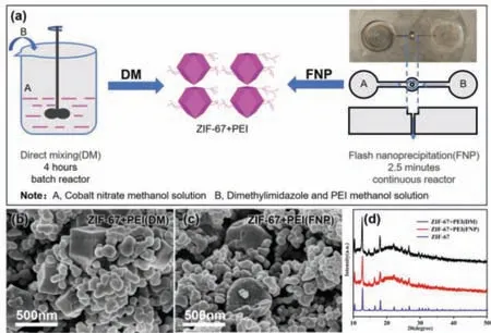
Fig.1.(a) Schematic diagram of the synthesis of ZIF-67+PEI(FNP) in a microchannel reactor.(b) SEM images of ZIF-67+PEI(DM) and (c) ZIF-67+PEI(FNP).(d) XRD spectra of ZIF-67+PEI(DM) and ZIF-67+PEI(FNP).
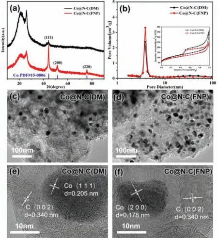
Fig.2.(a) XRD patterns of Co@N–C(DM) and Co@N–C(FNP).(b) N2 adsorptiondesorption isotherms and pore size distributions of Co@N–C(DM) and Co@N–C(FNP).(c) TEM images of Co@N–C(DM) and (d) Co@N–C(FNP).(e) HRTEM images of Co@N–C(DM) and (f) Co@N–C(FNP).
Fig.2a shows the XRD patterns of Co@N–C(DM) and Co@N–C(FNP) upon carbonization.A wide peak was observed at around 2θof 26° with an additional sharp peak nearby for both samples.The wide peak was associated with the (002) crystal plane of carbon,indicating the presence of graphitized carbon [36]; while the additional sharp peak was caused by the catalytic graphitization effect [37].Co@N–C(FNP) had other sharp diffraction peaks at 2θ=44.2°,51.5° and 75.8°,which were associated with Co (111),Co (200) and Co (220),respectively [38].On the other hand,Co@N–C(DM) only had a small diffraction peak at 2θ=44.2°,corresponding to Co (111).The XRD result showed that the crystallinity of Co in the sample prepared by microchannel reactor was higher than the one prepared by direct mixing.The Co content in Co@N–C(FNP) was 8.6 wt% by Inductive coupled plasma (ICP),which is more than 4 times higher than that in Co@N–C(DM) (1.9 wt%) (Table S2 in Supporting information).It is consistent with TEM observation in Figs.2c and d that more Co nanoparticles were found on Co@N–C(FNP) than on Co@N–C(DM),and the metal particles were uniformly dispersed.High resolution TEM (HRTEM) (Figs.2e and f) images showed that the lattice spacing in Co@N–C(DM) sample was 0.205 nm and 0.340 nm,corresponding to the Co (111) plane and C (002) plane,respectively; while the lattice spacing in Co@N–C(FNP) sample was 0.178 nm and 0.340 nm,corresponding to the Co (200) plane and C (002) plane [39],respectively.These results are consistent with previous XRD results.
The N2adsorption-desorption isotherms and pore size distributions of Co@N–C(DM) and Co@N–C(FNP) samples are shown in Fig.2b.Both samples exhibited type IV isotherm,indicating the presence of mesoporous structure.Co@N–C(FNP) had a BET specific surface area of 324 m2/g and an average pore diameter of 4.75 nm (Table S1 in Supporting information),which was smaller than that of Co@N–C(DM) (360 m2/g and 6.00 nm,respectively).This may be due to the fact that there were more Co nanoparticles in Co@N–C(FNP) than in Co@N–C(DM) which partially enter the pores of the catalyst,resulting in slightly smaller specific surface area and average pore diameter of the former.The element distribution of Co@N–C(FNP) catalyst was analyzed by EDS element mapping.It can be seen from Fig.S1 (Supporting information) that the elements of Co,C,N and O were evenly distributed,which indicated that the catalyst prepared by the microchannel reactor had good dispersion.
The Raman patterns of Co@N–C(DM) and Co@N–C(FNP) are shown in Fig.S2 (Supporting information).It can be seen that both catalysts had two obvious main peaks at 1344 cm-1and 1582 cm-1,corresponding to the D and G bands of the carbonaceous framework,respectively [40].The relatively higherID/IGof Co@N–C(FNP) than Co@N–C(DM) implied more defects present in Co@N–C(FNP) [41].The defects can increase the active sites for the adsorption of ORR intermediate,thereby enhancing catalytic activity.Meanwhile,the characteristic peak at 674 cm-1for Co@N–C(FNP)was caused by the vibration of Co-O bond [42],indicating the presence of Co oxide in the catalyst.The local surface oxidation of the catalyst can form a heterogeneous structure,which can further increase the catalytic activity [43].In addition,2D peak at 2681 cm-1was seen on Co@N–C(DM) but not on Co@N–C(FNP).This implied the existence of thick graphite structure in Co@N–C(FNP),which cannot only provide more edge positions and defects,but also be more durable and corrosion resistant than the thinner ones [44].
XPS results of the two samples are shown in Fig.S3 (Supporting information).The survey spectra of both Co@N–C(DM) and Co@N–C(FNP) showed the co-existence of C,N,O and Co elements.The Co content of Co@N–C(FNP) (0.56%) was higher than that of Co@N–C(DM) (0.37%) (Table S2).This is consistent with the results from ICP,XRD and TEM.The main form of carbon in both Co@N–C(DM)and Co@N–C(FNP) catalysts is C=C (284.8 eV) and C=N (285.6 eV),while the N element in the two catalysts is mainly pyridinic N(398.8 eV) and graphitic N (401.2 eV),with Co@N–C(DM) has additional oxidized N.By calculating the ratio of peak areas,the pyridinic N and graphitic N content in Co@N–C(FNP) was found to be about 26.3% and 70%,respectively,while that in Co@N–C(DM)was about 24.7% and 54.7%,respectively.It is reported that catalysts with pyridinic N and graphitic N have better oxygen reduction performance [45].The result implies that Co@N–C(FNP) is a more favorable catalyst of the two.Fig.S3d shows the Co 2p spectra and the Co elements were found to be in the form of Co0(778.7 eV) and Co2+(781.1 eV).Co@N–C(FNP) had a higher peak intensity than Co@N–C(DM),indicating more Co species with more active sites for ORR reaction.
The ORR activity of Co@N–C(FNP) catalyst was tested by cyclic voltammetry (CV) in 0.1 mol/L KOH saturated with N2and O2.As shown in Fig.3a,there was no reduction peak in N2-saturated electrolyte.An obvious reduction peak was seen in O2-saturated electrolyte,indicating that Co@N–C(FNP) catalyst had significant ORR electrocatalytic activity.In order to further understand the ORR kinetics,linear sweep voltammetry (LSV) was used to test a series of LSV curves of Co@N–C(FNP) catalyst with a speed range of 400–2500 rpm (Fig.3b).The current density of the voltammetry curve increased with the increase of the speed.When the voltage range of different rotating speeds was 0.4–0.7 V,the average electron transfer number was calculated to ben=4.01 based on the KL diagram obtained from the LSV curve (Fig.3d),indicating a fourelectron transfer mechanism in ORR process with Co@N–C(FNP)as the catalyst [46].Linear sweep voltammetry (LSV) was used to test the ORR performance of Co@N–C(DM) and Co@N–C(FNP)(Fig.3c).It was seen that the ORR catalytic activity of Co@N–C(FNP) (Eonset=0.92VRHE;E1/2= 0.83VRHE) was higher than that of Co@N–C(DM) (Eonset=0.90VRHE;E1/2= 0.83VRHE),which was mainly because of more Co species providing more active sites in the former.Moreover,Table S3 (Supporting information) summarizes the performance of metal-doped nitrogen and carbon catalysts prepared by different methods.Compared with other methods,the ORR performance of the catalyst prepared by microchannel reactor in this work has a great advantage in terms of the effi-cient production.
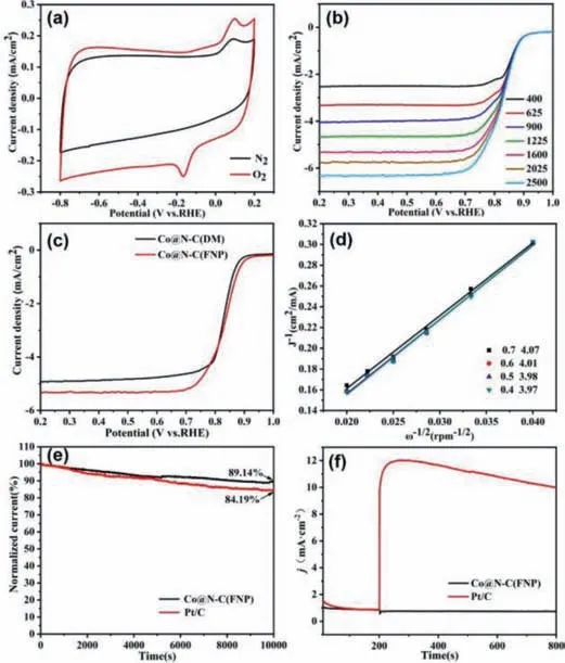
Fig.3.(a) CV curve of Co@N–C(FNP) in 0.1 mol/L KOH electrolyte at a rate of 50 mV.(b) LSV curve of Co@N–C(FNP).(c) LSV curve of Co@N–C(DM) and Co@N–C(FNP).(d) K-L curve of Co@N–C(FNP).(e) The ORR chrono-ampere (i-t) curve of Co@N–C(FNP) and 20% Pt/C saturated with O2 in 0.1 mol/L KOH at 1600 rpm.(f) Methanol resistance test of Co@N–C(FNP) and 20% Pt/C injected with 3 mL methanol after 200 s.
The stability of the catalyst is an important indicator that determines the service life of the fuel cell,so the ORR stability of the catalyst was evaluated using the chronoamperometry (Fig.3e).The current density of Co@N–C(FNP) can still retain at 89% of the initial value after 10,000 s,while the commercial 20% Pt/C remained at 84% of the initial value,indicating a better stability of the Co@N–C(FNP) catalyst than commercial Pt based catalyst.In addition to the stability,the resistance of the catalyst to methanol crossover is also a very important indicator.Therefore,after 200 s,3 mL of methanol was injected into the test tank containing 0.1 mol/L KOH electrolyte and continued till 800 s (Fig.3f).It can be seen that the addition of methanol caused obvious fluctuation for 20% Pt/C catalyst,but had little effect on Co@N–C(FNP),demonstrating good methanol tolerance of Co@N–C(FNP).
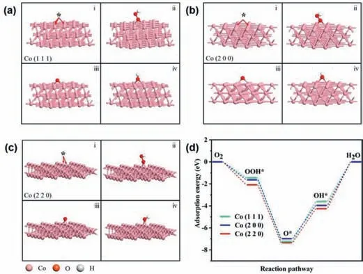
Fig.4.(a-c) Optimized structure of (i) *,(ii) OOH*,(iii) O*,and (iv) OH* adsorbed on (a) Co (111),(b) Co (200) and (c) Co (220).(d) Adsorption free-energy diagrams of the reduction of O2 to H2O on the Co (111),Co (200) and Co (220).
Zn-air battery was assembled by using Co@N–C(FNP) and commercial Pt/C as the cathode catalyst,respectively.The battery assembled with the Co@N–C(FNP) catalyst had a high open circuit voltage of 1.49 V (Fig.S4a in Supporting information),which is close to that of Pt/C (1.53 V).The peak power density of the battery assembled with Co@N–C(FNP) catalyst was 23 mW/cm2(Fig.S4b in Supporting information),which was slightly higher than that of the Pt/C catalyst (19 mW/cm2).The specific capacity of the battery assembled with the Co@N–C(FNP) catalyst was 761 mAh/g(Fig.S4c in Supporting information),which was much higher than that of the Pt/C catalyst (657 mAh/g).The results indicated that the assembled battery had a good durability and long service life,and the new battery can be prepared by replacing the zinc sheet.As shown in Fig.S4d (Supporting information),a 2.0 V red lightemitting diode (LED) can be lit up by connecting two cells made of Co@N–C(FNP) in series,indicating the promising application of Co@N–C(FNP) as the catalyst for Zn-air battery.
A consensus has been reached that different planes of metals will result in distinct electrocatalytic performance for ORR [47].Here,the XRD characterization clearly showed that the two catalysts Co@N–C(DM) and Co@N–C(FNP) prepared in this work are exposed to different crystal planes respectively.Therefore,it can be speculated that the exposed crystal plane structure of Co@N–C(FNP) catalyst can promote ORR more effectively.In order to prove this hypothesis,models of different crystal planes of Co species were established and calculated by DFT.Figs.4a-c show the optimal adsorption sites for OOH*,O*and OH*on Co (111),Co (200) and Co (220) crystal planes,respectively.It can be seen that the active sites for OOH*,O*and OH*adsorption are obviously different on different crystal planes.Therefore,the adsorption energy of transition state on different crystal planes is different when O2is reduced to H2O.The adsorption energy of Co (220)crystal plane is -2.08705 eV,-7.3474 eV,-4.25484 eV,respectively(Fig.4d).Its adsorption energy is greater than that of the other two crystal planes.In general,catalysts with stronger adsorption energy show better ORR performance.The results show that the adsorption energy of Co (220) crystal planes is stronger than that of Co(111) and Co (200) crystal planes.Therefore,this provides an explanation for the better ORR performance of Co@N–C(FNP) catalyst than that of Co@N–C(DM) catalyst.
In summary,ZIF-67+PEI(FNP) nanoparticles were synthesized from Co2+,2-methylimidazole and polyethyleneimine(PEI) in a microchannel reactor within minutes.Co@N–C(FNP) catalyst was obtained by carbonization of ZIF-67+PEI(FNP).The ORR performance of Co@N–C(FNP) was better than that of Co@N–C(DM) prepared by direct mixing method.One reason was that the ZIF-67+PEI(FNP)prepared by microchannel reactor was well dispersed and had a higher Co content after carbonization,which provided more active sites for ORR reaction.Moreover,density functional theory (DFT)calculations confirmed that the Co (220) crystal plane present in Co@N–C(FNP) have stronger adsorption energy than that of Co(111) crystal planes in Co@N–C(DM),leading to better electrocatalytic performance of the former.We also showed that the stability and methanol tolerance of Co@N–C(FNP) were better than commercial 20 wt% Pt/C.The Zn-air battery assembled with Co@N–C(FNP) as the cathode catalyst had high open circuit voltage,high power density and large specific capacity.The performance of these batteries has been comparable to that of Pt/C assembled batteries.Therefore,the microchannel reactor with the advantages of continuous operation and short reaction time provides a new method for the synthesis of metal organic framework compounds,which can effectively replace the direct mixing method.
Declaration of competing interest
The authors declare that they have no known competing financial interests or personal relationships that could have appeared to influence the work reported in this paper.
Acknowledgments
The work was supported by National Natural Science Foundation of China (No.21865025) and Science and Technology Innovation Talents Program of Bingtuan (No.2019CB025).
Supplementary materials
Supplementary material associated with this article can be found,in the online version,at doi:10.1016/j.cclet.2022.01.021.
 Chinese Chemical Letters2023年1期
- Chinese Chemical Letters的其它文章
- Diabetic wound healing activated by supramolecular cascade reaction
- MBenes: Two-dimensional transition-metal borides with ordered metal vacancies
- Wet-adhesive materials of oral and maxillofacial region: From design to application
- Diverse catalytic systems for nitrogen-heterocycle formation from O-acyl ketoximes
- Fluorine-containing drugs approved by the FDA in 2021
- The development and application of dual-comb spectroscopy in analytical chemistry
