Well-dispersed porous Fe–N–C catalyst towards the high-selective and high-efficiency conversion of CO2 to CO
Qiu-Hui Zheng,Chuang Chen,Si-Min Cao,Meng-Ting Peng,Bao-Xia Dong,Yun-Lei Teng
School of Chemistry and Chemical Engineering,Yangzhou University,Yangzhou 225002,China
Keywords:Electrochemical CO2 reduction Fe–N–C Metal-organic framework High-temperature pyrolysis Acid leaching
ABSTRACT In this study,through direct pyrolysis of a nitrogen-rich metal-organic framework of Fe-BTT at different temperatures and followed by acid treatment,we prepared a series of Fe–N–CT (T=800–1000 °C) composite catalysts with uniform cubic morphology and homogeneously distributed active sites.Acid leaching leads to the removal of excess Fe NPs and the exposure of more pyridinic N and porphyrin-like Fe–Nx sites and creates a higher specific surface area.Structural and electrochemical performance test results showed that Fe–N–C900 catalyst exhibited the highest selectivity for CO product at–1.2 V vs. Ag/AgCl,with 496 mV of overpotential and 86.8% of Faraday efficiency,as well as excellent long-term stability,due to the good inheritance from rich-N Fe–BTT precursor.
Partial combustion of fossil fuels causes excessive emission of CO2,creating environmental problems and energy crises.Solutions to this situation include using renewable energy sources,such as wind and solar,and the development of carbon capture,utilization,and storage (CCUS) technologies [1].Carbon utilization involves using CO2as a solvent or converting it into fuel and chemical precursors [2,3].The electrochemical CO2reduction reaction (CO2RR)is a desirable option to convert CO2into valuable chemicals and synthetic fuels,which has the advantage of operating at atmospheric pressure and room temperature [4].Besides,when combined with renewable energy sources,it can store the surplus electricity generated during peak production periods in a format of energy-intensive and easily transportable liquid fuel.CO2can be reduced to carbon-based products of formate,CO,hydrocarbons,and alcohols [5].At the current stage,the technical feasibility of CO2RR still faces some limitations,such as the low selectivity of the products,and the accompanied competitive hydrogen evolution reaction (HER) process due to the aqueous electrolyte.Moreover,the high kinetic barriers associated with CO2reduction and the multi-proton/electron transfer required for hydrocarbon formation result in a high overpotential of CO2RR,which transfers into significant energy loss [6].Aiming to find a catalyst with high effi-ciency,high stability,and low overpotential,various cathode catalysts,including four groups of single metal electrodes,metal complexes,carbon-based catalysts,etc.have been developed [7–9].
Metal-organic frameworks (MOFs) are a class of coordination polymers with a high specific surface area and high porosity,meanwhile,they have rich coordination styles between metal ions and organic ligands.Some of them have a high adsorption capacity for CO2,which is a prerequisite for CO2reduction [10].Therefore,MOFs with different metal nodes are promising and have been chosen as catalysts for CO2RR [11–13].However,the direct application of pristine MOFs to CO2RR still faces many challenges,that is,the poor conductivity,instability,and easy deactivation,which proposes a stricter requirement about the structure of MOFs.In consequence,the nitrogen-doped porous carbon material derived from MOFs has become a kind of promising CO2RR electrocatalyst due to its low cost,adjustable porosity,and abundant active sites.Previous studies have shown that the HER kinetics of carbon materials in aqueous solution is sluggish [14].The introduction of transition metals into N-doped carbon materials helps to significantly enhance the activity of CO2RR [4,15,16],especially the Fe–N–C catalyst reported by Juet al.,which can selectively reduce CO2to CO,and its catalytic performance is comparable to Au and Ag-based catalysts [17].
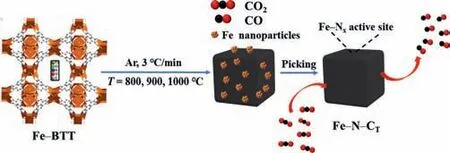
Scheme 1.Schematic diagram of the synthesis of Fe–N–CT material.
However,in the process of preparing Fe–N–C materials from high-temperature pyrolysis precursors,due to the newly formed C–C and C–N bonds,the carbon-based catalysts inevitably fuse and aggregate to form Fe nanoparticles (NPs),resulting in a decrease in the content of the effective Fe–Nxsites used for catalysis [18].Also,the non-uniform distribution of active sites,or encapsulation within the carbon matrix,makes it difficult for the reactants to reach the Fe–Nxsite.Huanet al.have developed a series of Fe–N–C catalysts with different active centers (Fe–N4or Fe NPs) [19].They have proved that the Fe–N4site is the crucial foundation for converting CO2to CO,and Fe NPs promote the HER.However,when compared with the N–C catalyst,the selectivity of Fe–N–C material is not improved substantially.Due to the strong binding ability between CO intermediate and Fe center,it brings more challenges for CO to desorb from the Fe–N–C catalyst thereby inhibiting the CO2RR process [17].Therefore,an efficient Fe–N–C catalyst requires sufficient iron content to form Fe–Nxactive sites and prevent the aggregation of iron NPs at the same time.For this purpose,it is essential to design an ideal electrocatalyst that exposure as many M–Nxactive sites as possible.
In our previous work,we have isolated the CuFe–N–C catalyst by introducing the ferrous ion into a microporous N-rich MOF of Cu–BTT which is constructed from tetrazolium [20].We have found that the mesoporous structure of the pyrolyzed materials is prominent as the Fe content increases,which is not only conducive to mass transfer but also contributes to exposing more active sites for full contact by the reactants.Nevertheless,the maximum FECOof the Fe0.07Cu–N–C800material is 47.8% with fierce HER competition,probably due to the existence of excess Fe NPs.Herein,we use Fe–BTT as the precursor for the preparation of Fe–N–CT(T=800,900,1000°C) composite catalysts with high content of Fe–Nxsites and well-dispersion (Scheme 1).After pyrolysis,it retains the precursors’shape and porous structure,while the conductivity and stability of the Fe–N–CTare enhanced,and the CO2RR activity is improved.The precursor of Fe3[(Fe4Cl)3(BTT)8]2·solvent (Fe–BTT) was synthesized from a solvothermal reaction of FeCl2·4H2O,H3BTT at a 3:1 molar ratio in a mixture of DMF and DMSO [21].The assynthesized light-yellow crystals,with uniform cubic morphology of 10~15 μm size,exhibit similar diffraction peaks with that of the simulated Fe–BTT based on the single-crystal structure (Figs.S1a and b in Supporting information).As shown in Fig.S1c (Supporting information),it behaves type I adsorption isotherm with a small hysteresis loop,which is probably due to the existence of a slight capillary condensation phenomenon [22].The BET surface area is given as 729 m2/g,lower than the reported 2010 m2/g[21].Thermogravimetric analysis of Fe–BTT was carried out in the range of 30–1000 °C,indicating that there is a large amount of solvent released below 300 °C,which should account for the partial activation of the porosity (Fig.S1d in Supporting information).Great weight loss from 300 °C to 600 °C could be attributed to the decomposition of BTT3–ligand,and there is no apparent change around 1000 °C.
The carbonization of Fe–BTT precursor was achieved through the pyrolysis process at 800,900,and 1000 °C,respectively,for 1 h at a slow heating rate of 3 °C/min,which were labeled as Fe–N–C800,Fe–N–C900,and Fe–N–C1000,respectively.The decomposition of BTT3–leaves plenty of iron NPs,as revealed by the PXRD characterization which exhibits a strong diffraction peak at 2θ=45.9° attributed to Fe (PDF #88–2324),for the directly pyrolyzed products(Fig.1).To expose more active sites of Fe–Nx,we used acid etching (4 mol/L HCl) to remove Fe NPs that were not active to CO2RR.As a result,for the catalysts after hydrochloric acid treatment,the diffraction signal of Fe disappeared.They also exhibit enhanced Fe3C (PDF #72–1110) signals at 2θ=44.9°,49.2°,and FeN0.05(PDF#75–2129) signals at 2θ=43.6°,50.8°,74.6° when comparing with the catalyst before acid leaching.
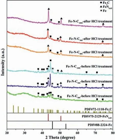
Fig.1.The PXRD patterns of the synthetic Fe–N–CT material before and after hydrochloric acid treatment.
To further demonstrate the effect of acid leaching,we performed TEM tests on each Fe–N–CTmaterial before and after acid treatment (Fig.S2 in Supporting information).Visible agglomerated Fe NPs on the surface of each sample could be observed (Figs.S2a–c),with 50–57 (Fe–N–C800),64–78 (Fe–N–C900),153–166 nm(Fe–N–C1000) size ranges,respectively,indicating that the agglomeration trend becomes more severe with the increase of temperature.They were significantly reduced but left little number of particles with smaller sizes after acid treatment (Figs.S2g–i).Based on the N2adsorption and desorption curves analysis,the specific surface area and micropore volume decrease after pyrolysis,which is caused by the collapse of the precursor and slight aggregation of Fe NPs during heating treatment (Fig.S3 and Table S1 in Supporting information).It’s worth noting that the mesoporous volume increases significantly after pyrolysis,which is verified by the prominent hysteresis loop ofP/P0in the range of 0.45–1.0 for each Fe–N–CTsample.More interestingly,after getting rid of substantial Fe NPs,the specific surface area and total pore volume,especially the mesoporous part,raise a lot,of which Fe–N–C900increases the most (551 m2/g,Vtotalpore=0.635 cm3/g).These advantages are beneficial to facilitating the mass transfer and exposing active sites for effective CO2RR.
Based on the above analysis,we can conclude that the acidtreated Fe–N–CTmaterials have the prerequisite and could expose more active sites for promoting CO2RR.Therefore,these catalysts were then subjected to the following tests.Raman spectroscopy characterizations show typical D and G bands at 1352 and 1580 cm–1,respectively,inferring the disordered and graphitized sp2carbon in them (Fig.S4 in Supporting information).TheID/IGratio of Fe–N–C900and Fe–N–C1000is very close to 0.90,indicating their amorphous carbon skeletons have similar defects [23].ICP and elemental analysis tests were also carried out to determine the content of Fe,C,N in each ternary composite (Table S2 in Supporting information).The results showed that the content of Fe and N follows a different trend with the increase of temperature,that is,Fe content increases and N decreases,which is probably due to the gradual removal of unstable N by raising the temperature.Moreover,the severer agglomeration at 1000 °C caused the hard elimination of Fe NPs even by acid leaching,consequently,the content of Fe is highest in Fe–N–C1000(of 12.45 wt%).We also conducted the SEM test to observe the influence of carbonization temperature on the microscopic morphology of each catalyst.As shown in Fig.S5 (Supporting information),it still preserves the uniform cubic morphology of Fe–BTT even under 1000 °C pyrolysis with evenly distributed C,N,O,and Fe elements.
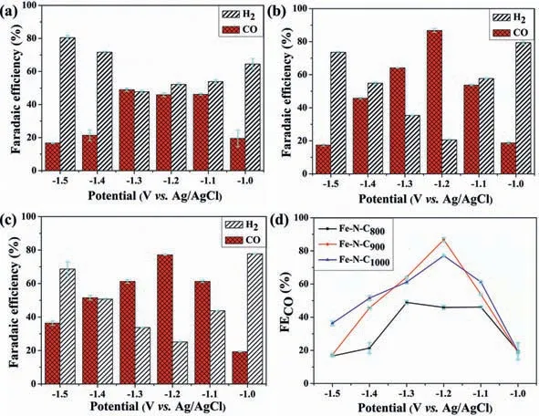
Fig.2.The selectivity for H2 and CO in the potential range of–1.0~–1.5 V vs. Ag/AgCl: (a) Fe–N–C800; (b) Fe–N–C900; (c) Fe–N–C1000.(d) Comparison of FECO for Fe–N–C800–1000.
With C 1s (284.80 eV) binding energy as the reference calibration peak position,we performed the XPS measurement to obtain the valence states of each element (Fe,N,C and O) in Fe–N–C800–1000(Fig.S6 in Supporting information).In the full spectrum,only the sample Fe–N–C800before hydrochloric acid-treated showed an unmistakable Fe signal.In contrast,all the materials treated with hydrochloric acid showed weak Fe spectrum lines,despite the high content of iron (2.57–12.45 wt%) being verified in them by ICP.Iron species were not detected by the surfacesensitive technique of XPS in Fe–N–C1000,hinting that they were immersed in the pores of the carbon matrix (Fig.S6b) [24].For Fe–N–C800and Fe–N–C900,more detailed analysis of Fe 2p regions were carried out,indicating the existence form of Fe0(707.9 eV),Fe2+(710.9 eV 2p3/2; 724.4 eV 2p1/2),and Fe3+(713.1 eV 2p3/2,726.6 eV 2p1/2).It is noteworthy that the Fe0signal is severely suppressed in Fe–N–C900,pointing to a higher concentration of Fe–Nxin it.According to the identification convention of typical M–N–C materials,we divided the N 1s spectrum into five types of N,which are pyridine N (398.2 eV),Fex–N (399.4 eV),pyrrole N (400.5±0.3 eV),graphite N or quaternary N (401.5 eV) and NO(402.6 eV),where the occurrence of Fe–Nxpeak indicates that the Fe–Nxunit has good inheritance after Fe–BTT pyrolysis (Fig.S6c)[24].Based on N percentage content analysis,we observed that the most considerable N contributions are mainly from pyridine N,pyrrole N,and Fe–Nx(Table S3 in Supporting information).With the increase of carbonization temperature,the content of pyridine N decreased,and the content of graphite N increased significantly(Fig.S6d in Supporting information),which is consistent with our previous conclusion [25].The acid leaching helps to the removal of major Fe NPs and leads to the exposure of more Fe–Nxsites,which is evidenced by the increase of Fe–Nxcontent in the sample Fe–N–C800after being treated by hydrochloric acid (9.65%vs.16.34%).
To further clarify the role of acid leaching on the CO2RR performance,we carried out the potentiostaic test for Fe–N–C800before and after acid treatment in a gas-tight H-type cell at–1.0~–1.5 Vvs.Ag/AgCl (Fig.S7 in Supporting information).Gaseous products CO and H2were detected by gas chromatography and were quantified based on the standard lines (Fig.S8 in Supporting information).H2is the main product (FEH2,62.0%-82.0%) for Fe–N–C800before treatment (FECO,0.9%-10.9%).It shows remarkable enhancement in FECOafter the acid treatment,especially in potential of–1.0~–1.3 Vvs.Ag/AgCl (19.5%-49.0%).Meanwhile,the FEH2was inhibited (52.1%-64.4%).The current density is similar in both catalysts.Combined with previous XRD,TEM and BET characterization results,we can confirm that the Fe NPs on the catalyst surface mainly promote the HER.Therefore,in preparing a Fe–N–C catalyst,the pre-treatment by hydrochloric acid is vital for preventing the aggregation of Fe NPs.The following discussion will concentrate on the Fe–N–C after pre-treatment.
Linear sweep voltammetry (LSV) test for each Fe–N–C in Aror CO2-saturated electrolytes were carried out,as shown in Fig.S9 (Supporting information).The reduction potential all appears earlier in the latter,indicating that the CO2RR is more active.It also reveals that Fe–N–C900catalyst possesses the highest current density and earliest onset potential (Fig.S9d in Supporting information).Stable electrolysis current was exhibited in all catalysts during the 2 hi-t-test with H2and CO generated as the main product (Fig.2 and Fig.S10 in Supporting information).The potential significantly affects the activity and selectivity of CO2RR.The FECOis improved remarkably in Fe–N–C900and Fe–N–C1000,of which maximum 86.8% and 77.1% FECOwere exhibited in them at–1.2 Vvs.Ag/AgCl,respectively.By taking the linear relationship between the overpotential and the fractional current density of CO at low potential,we got the Tafel curve for each catalyst (Fig.S11 in Supporting information).It displays the smallest Tafel slope in Fe–N–C900of 165 mV/decade,hinting at the fastest CO generation kinetics among Fe–N–C800–1000.Through the electrical impedance spectroscopy (EIS) tests,we also verified that it has the smallest impedance semicircle diameter (Fig.S12 in Supporting information).The charge transfer resistance is 6.48Ω,indicating that Fe–N–C900has a faster interface charge transfer process in the CO2reduction process (Table S4 in Supporting information) [26].Moreover,the electrochemical active area (ECSA) was evaluated through double-layer capacitance (Cdl) measurement (Fig.S13 in Supporting information).The biggestCdlwas yield in Fe–N–C900,giving rise to the highest ECSA of 371 cm2.
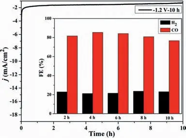
Fig.3.Electrolysis of Fe–N–C900 at–1.2 V vs. Ag/AgCl for 10 h.
Herein,Fe–N–C900was selected as the research object for stability study at–1.2 Vvs.Ag/AgCl.The current density reaches the platform quickly and maintains constantly for 10 h with an average value of 1.2 mA/cm2(Fig.3).The FECOand FEH2keep in 76%-85%,and 21%-23% during this period,with a stable H/C ratio of 0.24–0.29 which would be useful for the Fischer-Tropsch process (Table S5 in Supporting information) [27].
After digging the previous reports about Fe–N–C catalysts,the Fe–N–CTcatalyst synthesized through the direct pyrolysis of MOF precursor in this work has the advantages of method simplification,structural stability,excellent selectivity,and durability (Table S6 in Supporting information).According to a previous report,pyridine N,porphyrin-like Fe–Nx,and quaternary N structures play an essential role in the selectivity of CO2reduction[17,24,28].Among Fe–N–C800–1000,Fe–N–C800possesses the highest total N content,pyridinic N/Ntotal,and FeNx/Ntotalratios,with the Fe–N–C900being the second.However,the catalytic performance of the latter is outstanding.The prominent pore structure character of Fe–N–C900reminds us the specific surface area and pore volume would have an important impact on CO2RR.Regarding this topic,Strasseret al.used several Fe–N–C made by different nitrogen precursors (melamine,cyanamide,urea,nicarbazin)to explore the structure-activity relationship on transferring CO2to CO.A strong correlation between BET surface area and performance was established,of which the melamine precursor leads to the highest FECO(85%) with>800 m2/g BET surface area [24].Inconsistent with their findings,we observed that high content of pyridinic N,porphyrin-like Fe–Nx,as well as high specific surface areas,are facilitated to high CO production [26,29,30].The porphyrin-like Fe–N4has usually been recognized as the catalytic sites thanks to the appropriate binding strength with the intermediates.To elucidate the CO2RR mechanism on Fe–N–C catalyst,we employ a porphyrin-like Fe–N4embedded in a graphitic plane as the model for the DFT calculation.To draw the free energy profile of transferring CO2to CO,three steps were considered,that is,(1) CO2+*+H++e–→*COOH; (2)*COOH+H++e–→*CO+H2O;and (3)*CO →CO+*.As shown in Fig.S14 (Supporting information),the formation of*COOH requires overcoming an energy barrier of 0.54 eV,which is much more favorable for the formation of*H (1.014 eV).As a result,the HER is less active on Fe–N4–C than CO2RR.The ΔGrequired for desorption of*CO is 0.71 eV,which is the rate-determining step of CO2→CO.To facilitate the desorption of*CO,an appropriate binding strength with*CO and extensive mesoporous structure is especially important for highly effi-cient and durable electrocatalysts.
In conclusion,Fe–N–CT(T=800–1000 °C) composite catalyst with high specific surface area and uniform active sites was successfully prepared by the direct pyrolysis of Fe-BTT and followed by acid treatment.A series of characterization results showed that the mesoporous volume of Fe–N–CTincreased with the increase of temperature from 800 °C to 900 °C,which was beneficial to the mass transfer and the contact of the active site,thus improving their CO2RR performance.Elevating temperature to 1000 °C leads to obvious agglomeration of Fe NPs which would be isolated in pores of the carbon matrix and are hard to be removed by acid leading.The systematic electrochemical test indicated that Fe–N–C900catalyst showed the highest selectivity for CO product at–1.2 Vvs.Ag/AgCl,with 496 mV of overpotential,1.26 mA/cm2of current density,and 86.8% of Faraday efficiency,as well as excellent long-term stability.It behaves homogeneous distribution of pyridinic N and porphyrin-like Fe–Nxwith high content,and highest BET specific surface area,which is due to the good inheritance from rich-N Fe–BTT precursor.The catalyst studied in this paper also has the advantages of preparation method simplification and structural stability,which still preserves the uniform cubic morphology of the precursor even under high-temperature calcination.This work would provide a reference for preparing M–N–C catalysts with uniform active sites,high specific surface areas,and excellent selectivity for producing CO.
Declaration of competing interest
The authors declare that they have no known competing financial interests or personal relationships that could have appeared to influence the work reported in this paper.
Acknowledgments
The work is supported by the National Natural Science Foundation of China (No.21671169),and the Priority Academic Program Development of Jiangsu Higher Education Institutions.
Supplementary materials
Supplementary material associated with this article can be found,in the online version,at doi:10.1016/j.cclet.2022.02.078.
 Chinese Chemical Letters2023年1期
- Chinese Chemical Letters的其它文章
- Diabetic wound healing activated by supramolecular cascade reaction
- MBenes: Two-dimensional transition-metal borides with ordered metal vacancies
- Wet-adhesive materials of oral and maxillofacial region: From design to application
- Diverse catalytic systems for nitrogen-heterocycle formation from O-acyl ketoximes
- Fluorine-containing drugs approved by the FDA in 2021
- The development and application of dual-comb spectroscopy in analytical chemistry
