UAVs cooperative task assignment and trajectory optimization with safety and time constraints
Duo Zheng , Yun-fei Zhng , Fn Li , Peng Cheng
a UAV Autonomous Control Institute, Beijing Institute of Technology, Beijing,100081, China
b Shanghai Institute of Mechanical and Electrical Engineering, Shanghai, 201100, China
c CASIC Research Institute of Intelligent Decision Engineering, Wuhan,100074, China
Keywords:Multi-UAV Cooperative attacks Task assignment Trajectory optimization Safety constraints
ABSTRACT This paper proposes new methods and strategies for Multi-UAVs cooperative attacks with safety and time constraints in a complex environment.Delaunay triangle is designed to construct a map of the complex flight environment for aerial vehicles.Delaunay-Map, Safe Flight Corridor (SFC), and Relative Safe Flight Corridor (RSFC) are applied to ensure each UAV flight trajectory's safety.By using such techniques,it is possible to avoid the collision with obstacles and collision between UAVs.Bezier-curve is further developed to ensure that multi-UAVs can simultaneously reach the target at the specified time,and the trajectory is within the flight corridor.The trajectory tracking controller is also designed based on model predictive control to track the planned trajectory accurately.The simulation and experiment results are presented to verifying developed strategies of Multi-UAV cooperative attacks.
1.Introduction
UAVs are designed as an intelligent body of independent decision-making ability where multi-UAVs can perform complex tasks in coordination-this way of UAVs design is considered as the development trend of future UAVs.Simultaneously, breaking the limitations of traditional single-plane missions and using several UAVs to attack multiple targets in concert can effectively improve the damage efficiency and penetration probability, which will become an important combat mode in future wars.UAVs in complex environments(such as cities)have the advantages of hovering,reconnaissance, and flexibility.Rotor-wing drones (Loitering munition) have received widespread attention because a drone attack is quick, clean, and bloodless [1-4].For instance, Israel's“Firefly” and “Rotem” (shown in Fig.1) loitering munition, European GLMAV New concept loitering munition, Polish” dragonfly”loitering munition, are some examples of rotor-wing drones.Therefore, it is practical to study the cooperative attack of rotarywing UAVs in the complex combat environment.
To improve combat effectiveness, UAVs require to simultaneously attack several known targets from multiple directions in the premise of ensuring safety.Also, the complexity of the urban environment exacerbates the difficulty of realization[5-7].Therefore,the original cooperative attack issues are divided into two sub-problems, which are multi-task assignment and cooperative trajectory planning.
For task assignments, there is a large number of articles introduced in the literature.For UAVs search scenarios, the traveling salesman problem is often used to solve the problem realizing the traversal search of the target point by the UAV [8-10].For multimachine task allocation problems, mixed-integer optimization solutions are used for processing [11].Further, contract network solutions can effectively deal with task search and distribution problems according to different allocation costs[12,13].In addition,the problem of task allocation is the prerequisite of dealing with tasks in complex environments, and the problem of trajectory optimization is carried out on this basis.In this paper, instead of only considering the relationship between UAVs and the target, it opts to allocate the target based on the path planning result.

Fig.1. Rotary-wing UAVs: (a) Rotem; (b) firefly.
The problem of trajectory planning is to plan an optimal trajectory from the initial position to the end position with the safety and dynamic constraints [14].It is often carried out after the task assignment.An essential aspect of UAV autonomy is its ability to resolve encounters, which increases the difficulty of the solution[15].The classic UAVs trajectory problem commonly used a mixedinteger solver (MIQP).In Ref.[16], MIQP is utilized to enforce avoidance of both obstacles and other agents, at the expense of a long solution time;even the offline solution is also very difficult.In Ref.[17], Sequential Convex Programming (SCP) is adopted to convert nonconvex constraints into convex constraints.The optimal result is obtained by the iterative solution of the initial state.The result of this algorithm depends on the selection of the initial state,so it is more suitable as a local solver and is not suitable for complex environments.In Ref.[18], the artificial potential field method is used to establish the relationship between UAVs,and avoidance of other UAVs is carried out through repulsion.However,there was no solution that considered complex scenarios.Trajectory generation assisted by differential flatness property and geometric constrains has been becoming popular.Usually, a continuous convex SFC is established to constrain the trajectory of the UAVs so as to ensure that the constraint is a quadratic problem and solution time is finite[19-21].For the trajectory planning of multiple UAVs,the nature of the Bezier curve and the constraints of SFC are the best fit.Besides,the authors of Ref.[22]segmented the Bezier curve and increased the relative position constraints between the UAVs.A Relatively Safe Flight Corridor (RSFC) is utilized in Ref.[23]to achieve avoidance of the other UAVs based on a grid map; however, this method has disadvantages in a large map.In this paper, the property of RSFC and the design a novel method for generating collisionfree smooth multi-trajectory in Delaunay map are utilized.
The contributions of this paper are as follows:
(1) A path-based allocation method combined with an improved A* path search for finding the minimum cost function of multi-path.
(2) A Delaunay-based SFC algorithm utilizes the convex hull of the Bezier curve that guarantees the avoidance of obstacles.
(3) A Delaunay-based RSFC approach is based on the relative curve belonging to the Bezier curve to set the constraint to avoid collision of UAVs.
(4) An impact time control strategy to realize the UAVs cooperatively attack the target at a specified time.
The paper roadmap is as follows: Section 3 introduces the problem description and the mathematical formulation.Multiconstrain trajectory optimization and tracking control are described in section 4.The Delaunay-based SRF and Delaunaybased RSFC are detailed in section 5.In section 6, the simulation results and experiment are presented.The paper concludes in section 7.
2.Problem description
It is assumed that in a complex urban environment, there are multiple no-fly zones in a typical combat area (such as obstacles,enemy detection radars, firepower points, etc.).To implement the penetration as much as possible and increase the damage efficiency, it is necessary to attack targets simultaneously and avoid collision of obstacles and other UAVs.
As can be seen in Fig.2,there are multiple UAVs,UAV1UAV2,…UAVnU,and multiple mission target points,TA1TA2,…TAnTA,in the mission scenario.Considering the mission success probability and improving the damaging effect under actual conditions, the number of UAVs should be more than the target points.
2.1.Problem decomposition
According to Fig.2, to simplify the problem's difficulty, the entire task can be divided into two core tasks:task assignment and trajectory optimization.
Task 1: Multi-target task assignment.
Multi-task target allocation uses UAV resources to complete multi-target attacks at the lowest possible cost.Its mathematical expression can be expressed in the form of mixed-integer optimization, as stated in Eq.(1):
whereiurepresents theith UAV,itrepresents theith target point,Liu,itrepresents the length between theith UAV and theith target,ηiu,itrepresent the allocation array between UAV and target, andf(x)represents the cost between the UAViuand the target pointit.Eq.(1) aims to achieve the optimal cost function by assigning a corresponding target point to each UAV.
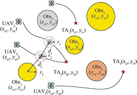
Fig.2. Multi-UAVs attack task scenario.
Task 2: Trajectory planning with a safety constraint.
To ensure the feasibility of executing the task, the planned trajectory needs to meet the constraints of obstacle avoidance and collision avoidance,time,and dynamics.The constraints of obstacle avoidance and collision avoidance,shown in Fig.2,are expressed by the following Eq.(2):
wherer1is the safe distance ofUAV1,r2is the safe distance ofUAV2,r3is the assumed obstacle threat distance,d1is the distance betweenUAV1andUAV2,andd2is the distance between obstacle and UAV.
2.2.Dynamic modeling
Considering quadrotor UAV as the research object, its dynamic model can be described by 12 state quantities,ωx,ωy,ωz].Following the footsteps of Ref.[15],state variables of the UAV are simplified.Some of them are selected;all other state variables are expressed through partial state variables and partial state variable derivatives.The flat output of the UAV system can be obtained using Eq.(3):
3.Map building and multi-targets attack task allocation
3.1.Map building and path search
Due to the complex and changeable presence of the battlefield environment, including radar detection, electromagnetic interference, enemy firepower, and many other threats, it poses severe challenges to the UAVs' mission.Moreover, these threats often cover irregular areas.The smallest circle is used to cover these danger factors,and the circular area is completely avoided through the path search algorithm.Furthermore,the absolute safety of the UAV flight path is ensured.Therefore, this paper chooses the Delaunay triangle method to divide the map.The construction method is as follows:
Step 1: Construct a super triangle, including all no-fly zones.
Step 2:Insert the scattered points in the no-fly zone one by one.
(1) Find the triangle whose circumcircle contains the insertion point in the triangle list (called the influence triangle of the point).
(2) Delete the common side of the influence triangle.
(3) Set the insertion point and all of the influence triangle.The vertices are connected to complete the insertion of a point in the Delaunay triangle linked list.
Step 3: Repeat step 2 until all the scattered points are inserted.
The Delaunay triangle takes the centers of various threats as nodes, divides the map according to the concept of maximum and minimum angles, and constructs the smallest triangle with the threat center as the vertex.The Delaunay triangle is described in Fig.3.Finally, the UAV position node is connected to the nearest node.Besides, the target position node is connected to the closest three nodes.On this basis,the path is searched with the midpoint of the triangle edge as the feasible path node.The waypoints obtained through the above construction method have the largest distance to the nearest threat node, ensuring the safety of the path.
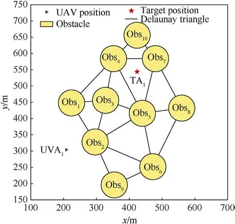
Fig.3. Search map.
Since the map is constructed through the Delaunay triangle,the number of nodes on the map is limited.The path search can be performed by heuristic algorithms such as A* algorithm.The construction method of A* algorithm includes the cost function and heuristic function of node transfer, as given in Eq.(4) and Eq.(5)
whereg(n)is the cost function of the distance between nodes,andh(n) is the heuristic function.
wheredn,n+1is the distance between the path node n and path nodesn+ 1, which represents the node transfer cost and is normalized by the scale factor α.
On the one hand,the Delaunay map guarantees the safety of the node at the midpoint of the triangle edge.On the other hand, it omits safety on the connecting line.So, the connecting line from node n to noden+1 is divided intoNparts and provide a cost function to value the relative safety and absolute safety.Then, the minimum distance betweenNnodes to the nearest obstacle is calculated, and make a judgment.If the minimum distance is less than the safety distance,r3,the minimum distance is set to 0.1 m to guarantee absolute safety.The relative safety function is calculated by Eq.(6)
To test the path safety,the map is established,and the test result is computed, as shown in Fig.4.
An optimal path can be searched through the above method in which the path cost and the threat cost are comprehensively considered.The optimal path is described in Fig.5.
3.2.Multi-targets attack task allocation with multi-angle constrains
To achieve multi-target coordinated attacks with little energy consumption, multiple targets need to be optimally allocated.Taking energy loss, threat factors, attack strength, and UAV distribution into account for target allocation, the cost functionf({Ui},{TAj},{Obsk}) is constructed, given by Eq.(7).
where[γ1,…,γit]represents the mapping between UAVsU1,…,Unuand target pointsTA1,…,TAnt, μforce[γ1,…,γit] represents the coordinated attack force, and μspread[γ1,…,γit] represents the distribution of UAVs.The function form is represented by Eq.(8)and Eq.(9).
wherem(it) represents the number of UAVs attacking the same target.
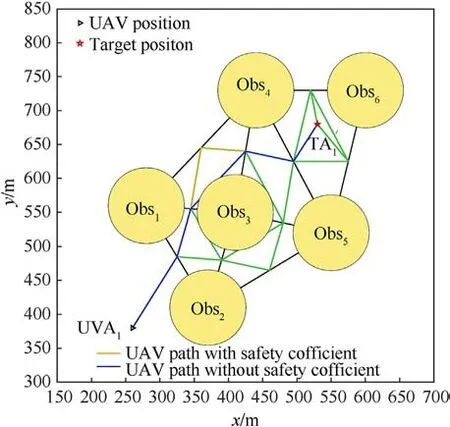
Fig.4. Safety test.
wheren(TA) represents the number of targets that are attacked.
In order to comprehensively consider these factors,the optimal cost function is obtained by optimizing the allocation of UAVs,and the optimization model can be expressed as the following form:
In order to increase the attack force and the success rate of combat missions to target points, the path of UAVs with the same mission and attack direction will be re-planned.Utilizing the end position node's connection method,we select other nodes with the same son-node (endpoint) as a new attack direction.
4.Multi-constrain trajectory optimization and tracking control
According to the above-mentioned path search method, the path of each UAV can be generated.Then,on this basis,a trajectory optimization algorithm is used to generate a flyable trajectory for minimum Jerk with obstacle avoidance and other UAVs constraints.The convex hull properties and the initial endpoint of the Beizer curve are used to optimize the trajectory.
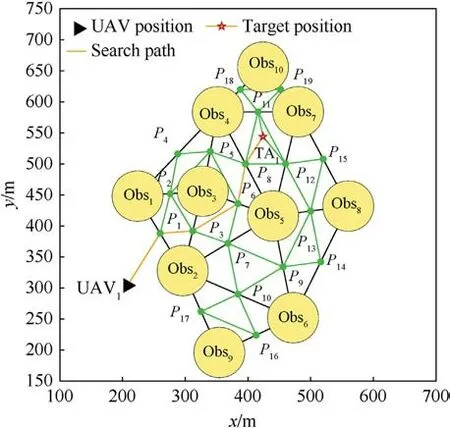
Fig.5. Search path.
4.1.Delaunay-based SFC for obstacle avoidance
UAVs cannot traverse every point on the original path to achieve collision avoidance between UAVs and satisfy UAVs' dynamic constraints.This is due to the coincident points on the original planned path are more likely to cause collisions between UAVs.Also, the flyable range of UAVs is expanded on the premise of safety.Moreover, expanding the flying area of UAVs establishes safe flight corridors for UAVs.Here,we utilize Berstein's convex hull property to constrain the optimal trajectory into the safety flight corridor to guarantee the UAV's safety.Then, a rectangular safety flight corridor (SFC) is established to meet the following constraints:
Among them, F represents free space and⊕is the sum of Minkowski.Besides, constraint (1) ensures the safety of SFC, and constraint (2) guarantees the continuity of SFC, which means that the intersection part connects the generated multiple trajectories.Each UAV path is obtained through the above map construction mode,task allocation,and search algorithm.To establish Delaunaybased SFC,the corridor along the axis direction is expanded,and it must be expanded in the direction of the vertical axis.The generated SFC is described in Fig.6.
The expression of constraint conditions is as follows:
Coupled with the initial position,velocity,and acceleration,the Inequality constraints are further increased.
Since the flight corridor is not expanded along the map axis direction but along the waypoints, the trajectory in thexorydirection cannot be planned independently but optimized by coupling.
4.2.Delaunay-based RSFC for collision avoidance
By establishing the above safe flight corridor,collision avoidance can be achieved as long as the path is in the safe flight corridor.Furthermore,the flight corridor's relative path is also established to ensure collision avoidance between UAVs.Assuming a relatively safe flight corridor for UAVsiandj,and this corridor is a relatively safe flight corridor that does not include the collision area,then the relative flight corridor (RSFC)satisfies the following constraints:
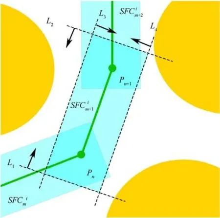
Fig.6. SFC for obstacle avoidance.
Among these constraints,Ci,jrepresents the relative collision model generated by the safety distance.Also,it is assumed that the safety radius of the UAViisri,and the safety radius of the UAVjisrj.Then, the relative collision model is considered as a square with a side length 2(ri+rj).Therefore,constraint(1)ensures the safety of the relative corridor, and constraint (2) ensures the continuity of the relatively safe corridor.
Since the map is constructed by the Delaunay triangle method,and the midpoint of the triangle is used as the path point,there are more overlapping nodes, which will cause the RSFC to be constructed unreasonably.Delaunay-based RSFC is constructed as follows:
Firstly,SFC constraints are applied to the UAV,and the optimized trajectory is obtained.
Secondly,the characteristic points on the trajectory are selected according to a certain time step,and the RSFC is constructed by the relative position relationship of the nodes corresponding to the optimized path.This step will increase the solution time but improve the feasibility of the solution.
Next, the way to build the flight corridor is considered.In the two-dimensional plane, μ∈{+x,-x,+y,-y} represents the axis direction,nμrepresents the unit vector, and the relative positionsatisfies constraint given in Eq.(12).

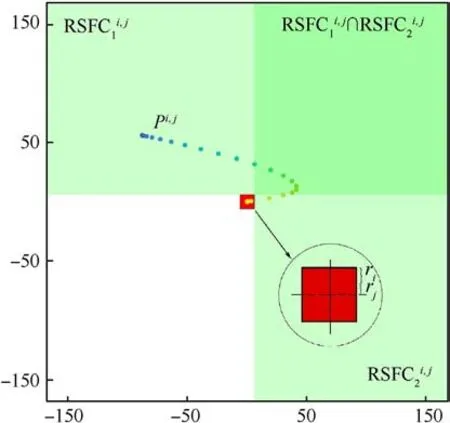
Fig.7. RSFC for collision avoidance.
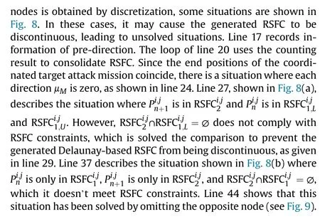
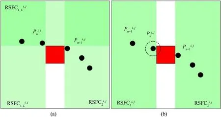
Fig.8. Situation of discontinuous RSFC situation: (a) Dispute node; (b) opposite node.
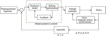
Fig.9. Control loop of trajectory tracking.

4.3.Time management
Simultaneously reaching multi-target UAV attacks is the key.Simultaneous attacks on a single target and multiple UAVs can increase the final attack strength.To achieve the required tasks, the first step is to obtain the total planning time.Since UAVs are required to arrive simultaneously, each UAV's timeTis the same.The longest path of all UAVs is selected as the reference path length.The total length of time is calculated based on the average speed of the UAV.Next, time distribution is performed according to the proportion of the segmented path to the respective path of the UAV,and the timeon each node path is obtained.Therefore, the collision avoidance algorithm is introduced in this article.The trajectory of the UAV must be limited to the safe flight corridor.Also,it is necessary to determine the constraint time of different RSFCs on the trajectory, allocate a reasonable time node, and realize the conversion of RSFC.(t) is the waypoint ofmtrajectory,t∈Then the time of theith UAV is expressed in Eq.(13).
In algorithm 2, the generation method of segment time is introduced.The inputs of the algorithm are the RSFC and the originally generated trajectory of each UAV.The algorithm establishes the relationship between the previous RSFC and the next RSFC by counting the number of original path points at the intersection of the two flight corridors (line 8 in the algorithm).However, there may be cases where the relative path is not on the intersection of RSFC (line 11 in the algorithm).In this case, we do not use the above method because the simultaneous conversion of SFC and RSFC will generate infeasible constraints.Instead,we use a heuristic method to set a delay to ensure that SFC and RSFC will not change simultaneously.This will increase the number of variables that need to be optimized,but this algorithm will ensure providing a feasible solution.
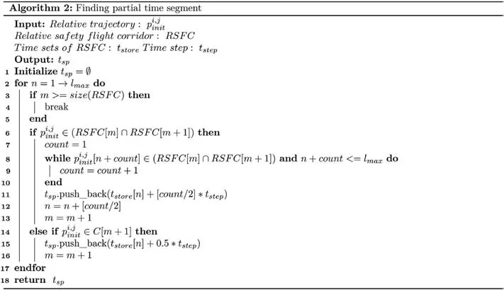
After generating local time trajectories, we integrate the trajectories of the relevant UAVs.Remove duplicate time elements and reorder.The total time segment generated is applied to the trajectory of the associated UAV.
4.4.Trajectory optimization based on Bezier curve
Trajectory optimization is to smooth the generated path points and meet the previously set time constraints for obstacle avoidance, collision avoidance, and simultaneous arrival.Coupled with UAVs'differential flatness,it is best to use the Bezier curve as UAVs'optimal trajectory.The Bezier curve is constructed based on the Bernstein polynomial:
The expression of the Bezier curve is stated in Eq.(14).
where the target is the λ th trajectory expression ofUAVi,is the weight function,bλ,k(t) is also called Bernstein polynomial,irepresents theith UAV, λ represents the λ th segmented curve.The expressionbλ,ib(t) is given by Eq.(15).
Among them,Nmeans that there areNcontrol points in this segment curve of UAV.In order to meet the time constraints of different periods, the time is mapped to τλ∈[0,1].
The Bezier curve has a convex hull property, which means that the curve is restricted to the convex hull formed by the control points,which can fit the safe flight corridor well and ensure that the UAV generates the trajectory is constrained in the safe corridor.
On the relative path, suppose one segment is the trajectory ofUAVi, and the other is the trajectory ofUAVj.By the integration of the above methods, the two UAVs are divided into the same number of segments, and the time for each segment of the two UAVs is also the same.Therefore, the relative trajectory is expressed, as stated in Eq.(17).
From the above equation, it can be seen that the relative trajectory between UAVs also fits the Bezier curve.Besides,the relative trajectory satisfies the convex hull property.Consequently, the control points of the corresponding segment of the original trajectory can be constrained to achieve the constraint on the relative trajectory and avoid collisions.
The cost function of the polynomial is as follows:
where λ is the λ th segment ofM.tλ is the time of λ th segment.Minimum target is theJerk.This minimizes the maneuvering of the UAV.
The smoothing constraints of the initial location point, the end location point, and the path point can be summarized as equation constraints.Therefore, our trajectory generation problem can be summarized as a linear quadratic programming problem.
where Q is the Hessian matrix,and Q is the Hessian matrix of each UAV formed by diagonal connections.We only need one QP problem to solve all smooth trajectories.
4.5.Model prediction tracking
To achieve engineering applications, we provide a trajectory method to test the flyable of optimal trajectory.This paper uses model predictive control to track the generated trajectory.Model predictive control mainly has three aspects, predictive model,rolling optimization, and feedback correction.
Since the system’s real-time state is measurable, a model predictive controller based on the state equation is established.The UAV needs to track the position, speed, and acceleration of the tracking design curve.The state equation is described using the following equations.
where x = [p,v,a]T,u=Jerk,
Suppose that the system input changes inMsteps from the momentk, and it acts on the system state at the nextP(P=M)moments.
Converted into vector description form:
where,
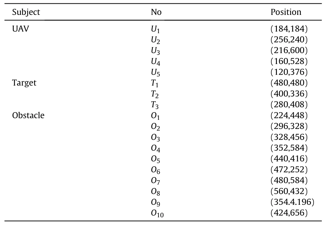
Table 1Environment information in the simulation.
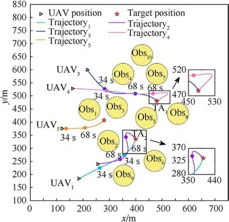
Fig.10. Multi-target allocation and optimal trajectory.
Consider determining theMcontrol variables fromkso that the predicted output value of the controlled object atPin the future is as close as possible to the expected value.We approximately write out the vector form of performance indicators as
Since the state quantity x(k)is measurable,the prediction made at each moment can be optimized.Besides, the measurement x(k)can be used as the initial position,which means that the prediction and optimization are all based on the system's real-time feedback information.Because of realizing feedback correction, no need to introduce additional correction measures.
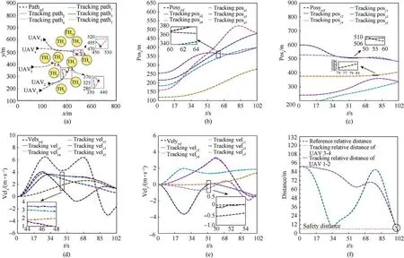
Fig.11. Simulation results:(a)Trajectory optimization and tracking;(b)Tracking result of px;(c)Tracking result of py;(d)Tracking result of vx;(e)Tracking result of vy;(f)Relative distance between UAVs.

Table 2UAVs impact time in the simulation.
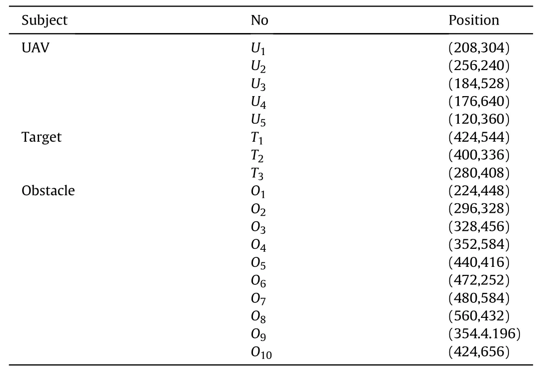
Table 3Environment information in the experiment.

Fig.12. Multi-target allocation and optimal trajectory in the actual environment.
5.Simulation and experiment
In order to verify the feasibility of the developed strategy for the multi-target cooperative attack,a test in the DJI simulation and the actual environment is performed.
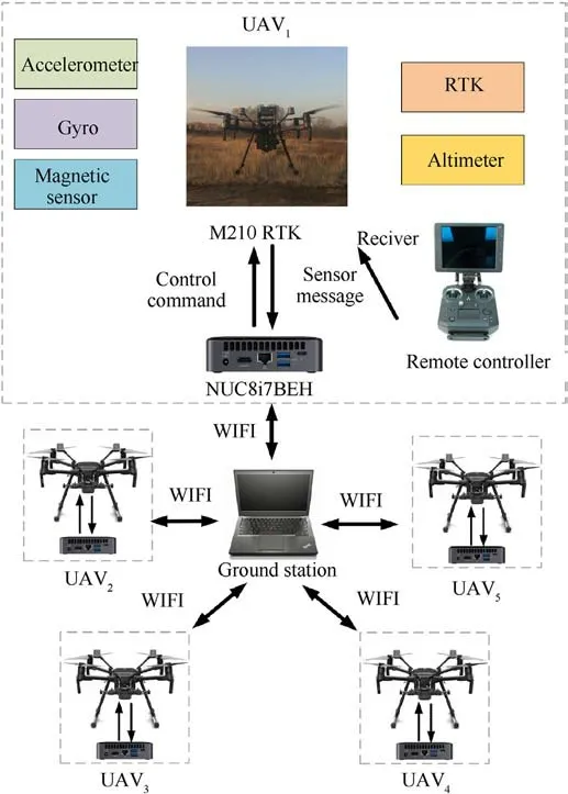
Fig.13. Experimental platform.

Table 4M210 parameters.
5.1.Simulation validate
The developed method in this paper is first tested in DJI simulation environment,DJI Assistant 2 For Matrice.A virtual map of 800×800 m2is created,in which there are 5 UAVs,3 target points,and several obstacles.The map information is shown in Table 1.
According to the proposed strategies, a search map is established in the simulation environment, and trajectory planning is performed to obtain the coordinated multi-directional attack path.The safety distanced1=6 m is set; also, the constraints of SFC,RSFC, and attack angle are added.The results of target allocation and optimal trajectory is given in Fig.10.
The simulation test to the trajectory is set as follows:
The gains of the tracking controller are set to ω1= 5,ω2= 0.1,ω3=0.01.To avoid the collision among drones at the endpoint,the stop condition s is set in which the miss distance is less than 4.2 m.
The result of the simulation is shown in Fig.11.
As can be seen in Fig.11, the results are shown in different charts.Fig.11(a)shows that the UAVs can accurately track the preplanned trajectory, avoid the obstacle, and reach the target position.Fig.11(b) and Fig.(c) show that in any axis direction position tracking, the position tracking error is within 2 m.Fig.11(d) and Fig.11(e) show that UAVs can track the predetermined velocity within the error of 0.3 m/s in any axis direction.We can see that the trajectory ofUAV5has a safety distance from other UAVs.Therefore, we only need to pay more attention to the relative distance betweenUAV3andUAV4,UAV1andUAV2.The results are confirmed in Fig.11(f).We can argue that when the relative distances are all greater than the required safety distance, UAVs can ensure that they avoid collisions with each other due to the task requirementUAV1andUAV2are allocated to attack targetTA2,UAV3andUAV4attack targetTA1.Therefore, they end up in the same target position,and the relative distance between UAVs is no longer restricted by the safety distance, shown as a circle in Fig.11(f).
In order to obtain the effectiveness of cooperation attack,UAVs are required to arrive at the target as possible at the same time;the results of the impact time for each UAV are shown in Table 2.
It can be concluded from Table 2 that the error between tracking results and pre-planned trajectory results is less than 1 s.The deviation of impact time of all UAVs is within 0.5 s,so we can say that all UAVs almost reach the target at the same time.
5.2.Experiment result
To verify the cooperation attack's actual performance, the preplanned trajectory was tracked and tested in the actual environment.We set virtual no-fly-zones in the actual environment,and its parameters are shown in Table 3.
The experiment platform is given in Fig.13,which uses the M210 drone, firmware version 01.00.0590, and NUC8i7BEH onboard computer (see Fig.12).The key parameters of M210 are shown in Table 4.
We set the gain of the trajectory tracking controller ω1=5,ω2=0.1, ω3= 0.01.The experimental result of trajectory tracking is shown in Fi.14.Also, the single direction of the position and the velocity following results are given in Fig.14(b) and Fig.14(c),Fig.14(d) and Fig.14(e), respectively.
According to Fig.14(a),Fig.14(b),and Fig.14(c),it is shown that the UAVs can follow the pre-planned trajectory within the error of 2 m avoiding the virtual obstacle and reaching the allocated target position.Fig.14 (d) and 14(e) show that the UAVs follow the predetermined velocity within the error of 0.5 m/s.We show the relative distance result in Fig.14(f).From the experiment, we can see that both relative distances betweenUAV1andUAV5,UAV3andUAV4satisfy the safety distance constraints, and the relative distance is greater thand1.
Table 5 shows the statistical results of the UAVs’ impact time.We could see that the impact time error between each UAV is less than 0.6 s,which means that the UAVs simultaneously attack three targets.The table also shows that the error of impact time between pre-planned trajectory and tracking result is less than 0.3 s.This proves that the UAVs can attack three targets at the specified time.
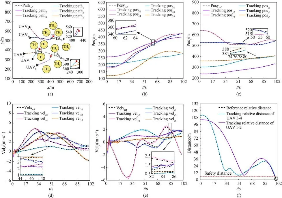
Fig.14. Experiment results:(a)Trajectory tracking;(b)Tracking result of px;(c)Tracking result of py;(d)Tracking result of vx;(e)Tracking result of vy;(f)Relative distance between UAVs.

Table 5UAVs impact time in the experiment.
6.Conclusions
This paper develops a novel strategy for task assignment and cooperation trajectory optimization of a UAVs group in a complex environment.The original problem is transformed into two subproblems, multi-target task assignments, and cooperation trajectory optimization.For UAVs task allocation, the proposed method utilized the multi-target allocation based on a search path to ensure that the task assignment's result has a feasible solution for planning trajectory.A Delaunay map for path planning was formed, taking the UAV path into account to enforce safety and minimum energy consumption.In cooperation trajectory optimization, UAV’s maneuverability, safety, and impact time constraints were considered.Compared with previous work, Delaunay-based SFC and Delaunay-based RSFC have been adapted to avoid obstacles collision and collision with other UAVs.The time scale factor is also to ensure the UAVs impact at the same time.In future work, the constraints of Delaunay-based RSFC will be further optimized,or a more efficient method will be studied to improve the success rate of an algorithm solution.
Funding information
National Natural Science Foundation of China (No.61903350),Beijing Institute of Technology Research Fund Program for Young Scholars.
Declaration of competing interest
The authors declare that they have no known competing financial interests or personal relationships that could have appeared to influence the work reported in this paper.
- Defence Technology的其它文章
- Mechanical behavior of entangled metallic wire materialspolyurethane interpenetrating composites
- Investigation on thermal characteristics and desensitization mechanism of improved step ladder-structured nitrocellulose
- 2D metal-organic frameworks endow ammonium perchlorate with enhanced thermal effect
- Thermal decomposition effect of MgCo2O4 nanosheets on ammonium perchlorate-based energetic molecular perovskites
- Modification of SDOF model for reinforced concrete beams under close-in explosion
- Air combat target maneuver trajectory prediction based on robust regularized Volterra series and adaptive ensemble online transfer learning

