
Recent progress and perspectives in additive manufacturing of magnesium alloys
2022-07-26 11:40:52ZhuornZengMojtSlehiAlexnerKoppShiweiXuMroEsmilyNikBirilis
Journal of Magnesium and Alloys 2022年6期
Zhuorn Zeng ,Mojt Slehi ,Alexner Kopp ,Shiwei Xu ,Mro Esmily ,Nik Birilis
a College of Engineering and Computer Science,Australian National University,ACT.2601 Australia
b Additive Manufacturing Group,Singapore Institute of Manufacturing Technology (SIMTech),Agency for,Science,Technology and Research (A∗STAR),73 Nanyang Drive,637662 Singapore
cMeotec GmbH,Philipsstr.8,Aachen,Germany
d State Key Laboratory of Advanced Design and Manufacturing for Vehicle Body,Hunan University,Changsha,410082 China
e Department of Materials Science and Engineering,Massachusetts Institute of Technology,Cambridge,MA 02139,United States of America
fVolvo Materials Technology Laboratory,Volvo Group,Lundby,Gothenburg 417 15,Sweden
Abstract Magnesium alloys remain critical in the context of light-weighting and advanced devices.The increased utilisation of magnesium (Mg)each year reveals growing demand for its Mg-based alloys.Additive manufacturing (AM) provides the possibility to directly manufacture components in net-shape,providing new possibilities and applications for the use of Mg-alloys,and new prospects in the utilisation of novel physical structures made possible from ‘3D printing’.The review herein seeks to holistically explore the additive manufacturing of Mg-alloys to date,including a synopsis of processes used and properties measured (with a comparison to conventionally prepared Mg-alloys).The challenges and possibilities of AM Mg-alloys are critically elaborated for the fiel of mechanical metallurgy.
Keywords: Magnesium;Additive manufacturing;Microstructure;3D printing;Mechanical properties;Electrochemical properties.
1.Introduction
Magnesium (Mg) has the lowest density (1.74 g/cm3) of the engineering metals,approximately 65%the density of aluminium alloys,38% that of titanium,and 25% that of steel.The high specifi strength of Mg alloys makes them attractive materials for light-weighting in automotive,consumer electronics,and aerospace applications [1].Magnesium alloys are also biodegradable and have an elastic modulus (~45 GPa)analogous to that of human bone.Magnesium ions(Mg2+)are required for numerous biochemical reactions in the human body,and they enhance metabolism and mediate osteoblast proliferation [2].Consequently,Mg alloys are also being considered for use in the medical field e.g.orthopaedics,maxillofacial applications,and cardiology [3].Today,>95% of Mg alloy products are produced by casting (including pressure die casting),whilst wrought Mg alloys have limited applications,predominantly due to insufficien formability and processability at room temperature [4-6].

Fig.1.Laser powder-bed fusion prepared lattice structure in the shape of ‘Mg’,produced in Mg-alloy WE43 (Image courtesy Meotec GmbH and Dr.M.Esmaily).
Additive manufacturing (AM) of Mg alloys is of growing interest in the materials community due to AM enabling design capabilities not achievable with traditional manufacturing and presumably also material properties unknown so far.Additive manufacturing presents several unique advantages such as design freedom(and topology optimisation),minimal waste of resources,and reduced energy usage [7].Additionally,AM overcomes the limitation of conventional (formative or subtractive)fabrication routes.The ability to produce complex internal and external geometries with high precision enables the development of precise geometrical features (see the complex lattice geometry in Fig.1).Design freedom enables one to make the lightest engineering metal even lighter via topology optimisation and the use of free space as a design variable.Additionally,components with a large surface area would promote cell growth,proliferation and bone regeneration if used as biomaterials;or provide significan reaction area if used as Mg electrodes.The AM-Mg technology is expected to address the high demand of high-performance biodegradable implants for orthopaedic and vascular surgery,and make manufacturing of patient-specifi and topologically-optimised implants technically feasible.Furthermore,the precise control over process parameters can yield alloys with tailored microstructures and properties.This has been demonstrated in recent studies reporting successful production of new Al-,Fe-,and Ti-based alloys with enhanced properties using various AM techniques[8-10].
Nevertheless,research in the fiel of AM-Mg alloys has been limited to date.This may be in part due to the reactive nature of magnesium (in atmospheric conditions),which raises health and safety concerns,in addition to other issues concerning the oxidation,evaporation and handling of Mg powder.However,as noted by the research outcomes since 2010(Fig.2)[11],risk controls during the LPBF process have demonstrated great success in allowing the Mg-powder based additive method to be routinely and reproducibly utilised to safely manufacture Mg-alloys of diverse composition.The protective measures include (1) handling/storing Mg alloy powders in fire-resistan safety storage cabinets and appropriate quantities;(2) personnel training in managing situations that may require control measures to be implemented;(3)preparing and cleaning the LPBF machine’s filte and processing chamber,including the removal of all potential ignition causes such as electrostatic discharge;and (4) controlling reaction gasses prior to and during additive manufacturing.Apart from the safety concern,another issue that limited the development of LPBF-Mg alloy is the quality consistency of Mg powder.Mg powder is constantly changing properties and hence you will not fin fi ed LPBF parameters.
In addition to the laser-powder based additive manufacturing,diverse additive manufacturing methods have also been explored,including sintering,wire-arc additive manufacturing(WAAM),friction-stir processing,and inkjet methods.Although whether these diverse methods can be regarded as‘additive manufacturing’ is still under debate in the community,we still accept that they are following an ‘additive’ strategy in a general sense,and thus include them in this review.Given that additive manufacturing technology has been wellreviewed by Debroy et al.[12],this present review will focus solely on AM-Mg only (rather than AM technology in general),which presents a number of unique characteristics from other AM alloy systems,such as Al,Ti,and steels.Compared with these comparatively more well-studied alloy systems,studies regarding various aspects of AM-Mg remain primitive or wholly unexplored.To date,although several consolidated reviews regarding additive manufacturing of magnesium have been published [13-17],the composition-processingmicrostructure-property relationship in AM-Mg has not been systematically explored (or established) yet.A major reason for this is that results of microstructure-property relationships for AM-Mg alloys have revealed some discrepancies in different reports.The purpose of this review is to summarise the recent progress in AM-Mg,to systematically study and critically analyse the results reported so far;and to allow the key factor that governs the microstructure and properties of AMMg to be revealed.In summarising,some of the challenges for AM-Mg will be discussed and a future outlook will be provided.

Fig.2.Timeline displaying a historical background of powder-based AM-Mg research and development,indicating "landmarks" since the firs scientifi study on the utilisation of AM to sinter Mg powder.Reproduced from [11].
2.Laser-based additive manufacturing
2.1.Characteristics of laser-based methods
Laser,the most widely investigated energy source for AMMg,has some unique advantages over other energy sources[18].The high-intensity laser beams irradiated onto the printing material can be efficientl absorbed without any transfer medium.As lasers generate spatially coherent light contrary to incoherent sources,such as thermal lamps or light-emitting diodes (LEDs),the laser beams propagate without critical beam divergence or power loss over long distances,and also can be focused into small spots(down to~60 μm in diameter or even below),so they can provide the improved precision and throughput in 3D part construction.Lasers produce a high concentration of heat that is focused at small regions of the powder bed for limited amounts of time,to melt the powder.This short-timed heat flu causes rapid heating and quenching of the molten powder leading to rapid solidificatio [19].In the additive manufacturing of Mg alloys,the most-widely explored method is laser powder-bed fusion (LPBF,formerly known as selective laser melting,SLM),with very few explorations adopting direct laser deposition (DLD).
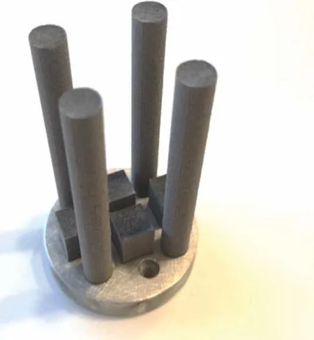
Fig.3.LPBF of Mg alloys in cylindric and cubic shape in a reduced volume system (Image courtesy Meotec GmbH).
The Laser powder-bed fusion (LPBF) process is now considered to be a powerful and efficien additive manufacturing process for building complex 3D shapes with a high degree of precision and reproducibility,combined with satisfactory metallurgical properties (Fig.3).The general characteristics of LPBF have been previously reviewed [12],however,a unique characteristic of Mg that differentiates its behaviour from other engineering metals is its low evaporation temperature.The evaporation point of Mg is 1091 °C,whilst the evaporation points of Al and Ti are 2470 °C and 3287 °C.Therefore,the temperature during LPBF will certainly be above the evaporation temperature of Mg,and cause an overall change in Mg alloy composition due to preferential evaporation of Mg.We et al.[20] systematically studied the evaporation during LPBF (Fig.4).It was found that the temperature increase in the melt pool significantl accelerates the burning rate of Mg(Fig.4a).For AZ91 alloy,in the temperature regime between 870 K (liquidus temperature of AZ91) and 2000 K,the evaporation rate of Mg is about 4.2 × 10⁴-3.5 × 1010,54-160,and 2.3 × 10⁵-3.5 × 10⁹times faster than Al,Zn,and Mn,respectively (Figs.4b -d).The temperature of the melt pool is affected by several processing parameters,including laser power,scan speed,hatch spacing,layer thickness,and thus a concept,input energy density,Evis introduced to include all these factors as Ev=where P is the laser power,S is hatch spacing,and L is the layer thickness.A numerical model is developed to predict the composition accuracy of AZ91 as a function of input energy density [20].It can be observed that there is an optimum value of input power density around 60 J/mm3(Fig.4e).A higher Evwill lead to a more severe preferential evaporation of Mg so that the Mg/Al ratio decreases to 7:1 (Mg-13Al,wt.%).It is also interesting to see the Mg/Al ratio at lower Ev.This is because the thermal conductivity of powder is much less than consolidated bulk,and at low Ev,the size of the melt pool is too small to penetrate the powder layer.The poor thermal conductivity of the powder layer results in a local high temperature of the melt pool,which in turn facilitates evaporation of Mg.This has demonstrated that to avoid severe evaporation and to keep compositional accuracy,the processing window for the LPBF of Mg alloy is much limited.
In addition to evaporation,porosity,which is a common issue for all LPBF metals materials,must be taken into consideration.There are several mechanisms regarding the formation of pores,which are,again,functions of processing parameters (Fig.5a) [21].For magnesium specificall,the effect of processing parameters on porosity is summarised in Table 1 [11,22-42].It is difficul to extract a trend regarding the effect of any individual processing parameter on the relative density because changing any one of the listed parameters would result in different porosity.Therefore,the energy input density,Ev,is used to represent the combined effects of these parameters,and it is now apparent from Fig.5b that there is an optimum regime of Evvalue for each alloy system.For Mg-Al based alloy,the optimum energy density relies between 100 and 200 J/mm3and several alloys have high relative density>99% Fig.5c.However,several Mg-Al-based data points between 100 and 200 J/mm3still show a much lower relative density even less than 80%.By sourcing the reference paper,it is found that powders for LPBF are blended Mg and Al,rather than pre-alloyed Mg-Al powders [24,25].This suggests that it may be far more difficul to achieve high relative density using blended elemental metal powders,because the different thermal properties of each element may lead to significan local incompatibility during rapid cooling.The Mg-RE-based alloys seem to have a larger processing window (50 to 250 J/mm3) to achieve low porosity(<1%),and the highest relative density of Mg-RE-based alloy is nearly fully dense e.g.99.8% to 99.9%,whilst the highest relative density of Mg-Al-based alloy is 99.5%.In contrast,very few Mg-Zn-based alloys have achieved high density.Wei et al.[39] systematically investigated the effect of Zn concentration on alloy processability in LPBF.Despite a similar Evvalue (183 J/mm3),the high relative density (~99%) can only be achieved when Zn concentration is very low (1 wt.%)or high (12 wt.%).In the middle,Mg-6Zn alloy shows the lowest relative,which is not commonly observed in Mg-Al or Mg-RE alloys.Therefore,having identifie the optimum processing window,the ‘printability’,dictated by alloy composition,is critical to achieving high density and low porosity.The studied alloy so far will be reviewed in the coming section.

Fig.4.Evaporation rate of Mg (JMg) and the alloying elements ratios in AZ91D molten pools under various temperatures (JAl,JZn and JMn—burning rates of Al,Zn and Mn,respectively) (a) JMg (b) JMg/JAl (c) JMg/JZn (d) JMg/JMn.(e) Mg/Al weight ratio (η) of different samples and the fitte relation between η and laser energy density (EV).Reproduced from [20].

Table 1 Processing-relative density of additive manufactured Mg and alloys [11,22-42].

Table 1 (continued)

Fig.5.(a) Schematic illustration of processing window and relevant defect,(b) relative density as a function of energy input density of LPBF-Mg alloys reported up to date [11,22-42],and (c) those sample with high relative density (≥99%).
Whilst pororsity is inevitable and thus a certain degree of porosity is acceptable,hot tearing and cracking must be avoided.In LPBF,hot tearing and crack are the most severe issues that deteriorate the quality of the as-built component.In general,the susceptibility to hot tearing is particularly higher between columnar grains,which are formed when the constitutional supercooling becomes much lower,but the temperature gradient remains high.As temperature and liquid volume fraction decrease,volumetric solidificatio shrinkage and thermal contraction between columnar grains produce cavities and hot-tearing cracks,which can span the entire length of the columnar grain.To date,due to limited research,the effects of alloying and processing conditions on hot tearing in Mg during LPBF are unclear.Emperically,the alloy with columnar grains and large solidificatio range,such as Mg-6Zn [39],is more prone to cracking.Systematic studies are required to illustrate crack formation mechanism as a function of composition and LPBF parameters in Mg alloys.
2.2.Alloy systems investigated
Compared with cast and wrought alloy,much fewer compositions have been explored for additive manufacturing.This is predominantly caused by the high cost associated with the customised production of atomised pre-alloyed powder,which could be thousands of times higher than the cost of customisation of cast or wrought alloy composition.Nowadays,the commercialised compositions of Mg for additive manufacturing include pure Mg,AZ91,and WE43,predominantly due to their comparatively larger market demand,better printability,and properties for structural and biomedical applications.Even these compositions are not really“commercialised”,one can buy them,but for sure not“off the shelf”.
2.2.1.Pure Mg-based alloys
The earliest trial of laser additive manufacturing of pure Mg was achieved in pure Mg by Ng et al.from the Hong Kong Polytechnic University around 2010 using a customised LPBF system with Nd:YAG laser [43,44].In these studies,different laser power and scan speed were tried for single track laser scan,and it was found that LPBF could not be performed with the coarse and irregular powder,but could be successful with atomised fin and spherical powders at appropriate conditions [43].The grain size of LPBF pure Mg was only about 2-5 μm [44].Previously,such a small grain size in pure Mg can only be achieved by severe plastic deformation at low temperatures [45].This demonstrates the potency of microstructure refinemen of LPBF,a key advantage over conventional casting and thermomechanical processing.The hardness reported in this report is incredibly high,from 60 -89 HV (0.59 -0.87 GPa) [44].However,a high density of oxides and cracks were observed along the grain boundaries of the LPBF single-track sample.
The firs bulk pure Mg produced by LPBF is reported by Hu et al.from Chongqing University[23].The spherical powders with two different sizes (26 and 43 μm) were used for LPBF,and were provided by Tangshan Weihao Magnesium Powder Co.Ltd,which seems to provide most of powders for LPBF research in China.Based on the data provided [23],a processing window for LPBF pure Mg in this review,which is quite small (Fig.6).The insufficien input energy density(low power or fast scan speed) cannot make a consolidated building,whilst a high power input results in severe evaporation.Even within the processing window,the highest relative density is reportedly 97.5% [22],which is still less than>99% (normally required for industry application).Close examination shows a high density of gas pores and irregular lack-of-fusion pores,and some pores are interconnected [22].Apart from LPBF,DLD was used as a method of additive manufacturing [46,47].In these studies,coarser particles with irregular shapes were used as feedstock materials.The asbuilt sample has a much rougher surface finis and larger and denser pores and cracks.
2.2.2.Mg-Al-based alloys
Amongst Mg-Al based alloy,AZ31 is the most important commercial composition in cast and wrought forms.However,for laser-powder-based additive manufacturing,the number of literature is very limited,whilst most AZ31 for additive manufacturing is based on the wire-arc method.In fact,the majority of laser-based Mg-Al alloys are with high Al concentrations,such as AZ91.This is because Al provides strengthening by solute and Mg17Al12intermetallic phase,improves castability(thus ‘printability’),and the presence of Al requires that the alloys be grain refine by super-heating or inoculation [1].Nevertheless,Pawlak et al.studied LPBF process of AZ31 and achieved a low porosity level (<0.5%) [48].Such a low porosity level is also achieved in AZ61 and AZ91 in LPBF,demonstrating the acceptable‘printability’of Mg-Al-based alloy.
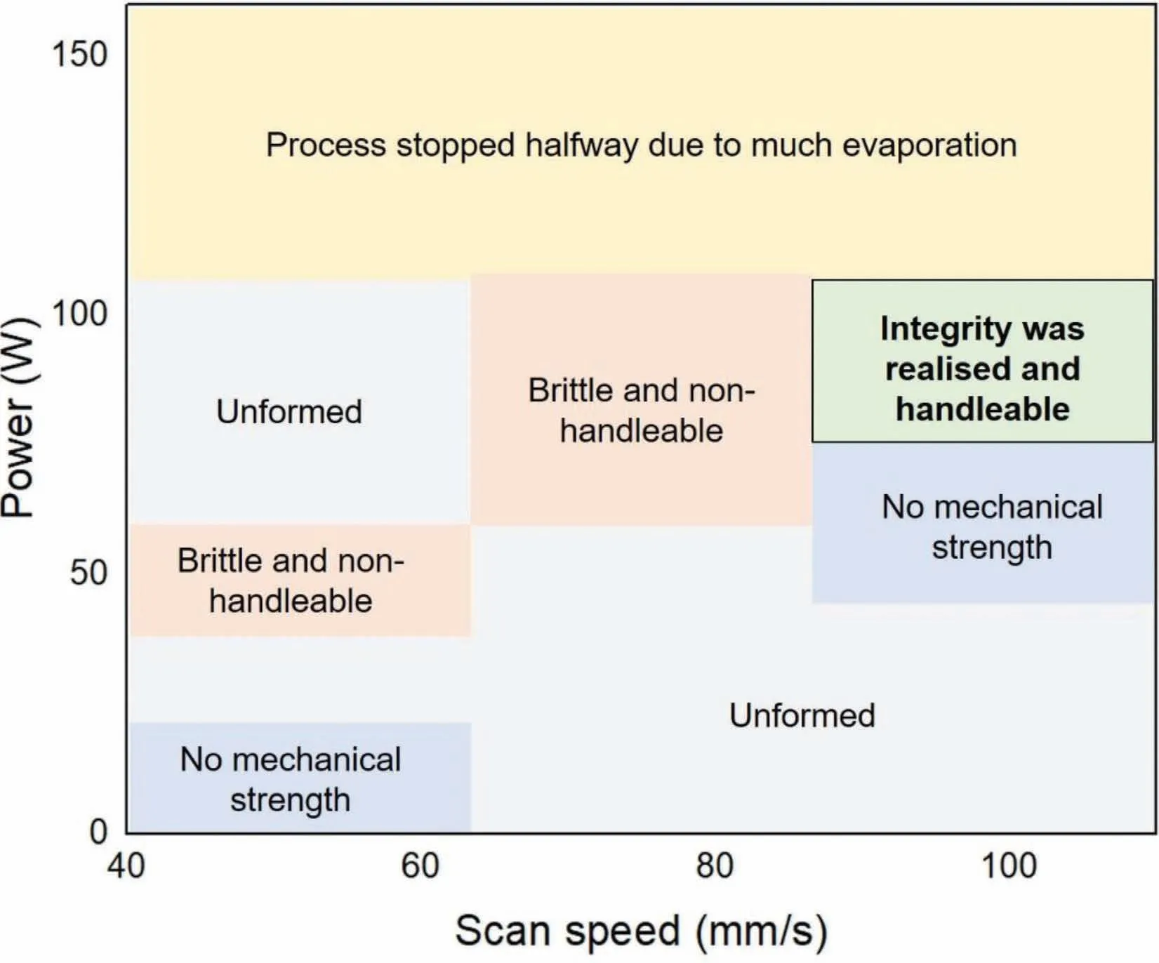
Fig.6.Processing window of pure Mg in LPBF,data from [23].
The LPBF AZ61 [26,27] and AZ91 alloys demonstrated fin and equiaxed grain with nearly random texture.The grain size can be as small as 1 -3 μm (Fig.7a).In some studies,the Mg17Al12intermetallics are distributed along the grain boundaries and interconnected (Fig.7b),and the grain interior is essentially particle-free [26-31].However,our unpublished results show elongated grains along the building direction (Fig.7c).There are two forms of Mg17Al12intermetallic phase.One is those distributed along the grain boundaries,but there are high density of spherical Mg17Al12nano-particles with a diameter of 100 -300 nm inside grains (Fig.7d).The LPBF conditions for this case is 50 W laser power,400 mm/s scan speed,40 μm hatching distance and 30 μm layer thickness,resulting in an input energy density of 104 J/mm3.The input energy density in our case is very similar to that reported by Jauer et al.[30],Jauer et al.used a higher power(100 W) and faster scan speed (800 mm/s).This may be probably a reason for such different microstructures between these two samples (Fig.7),but the mechanism is still to be explored.The comparison of the two cases demonstrates that the microstructure of LPBF AZ-based alloy is tunable by adjusting processing parameters.
2.2.3.Mg-RE-based alloys
Amongst the Mg-RE system,additive manufacturing of WE43 alloy is most widely studied for biomedical implant applications.As aforementioned,WE43 alloy has good printability,and it has an even larger processing window to achieve low porosity than AZ91 alloy.Moreover,WE43 is biocompatible,and does adverse cell reactions such as cytotoxicity,but Al is.Indeed,Al is neurotoxic element and banned from bioabsorbable Mg alloys in fear of Alzheimer’s disease.Hence,WE43 has attracted more attention for biodegradable implants,such as scaffolds.
In the early studies,Zumdick and Jauer[30,32]have shown a refine and nearly uniformly equiaxed microstructure of LPBF WE43 (Fig.8a),despite some very small number grains with abnormal grain growth during LPBF.The size of equiaxed grain is about 1 -3 μm,and they have nearly randomised orientations.Interestingly,later in 2019,despite using the same processing conditions from the same research group,the LPBF WE43 show a totally different microstructure,in which large and strong-basal-textured grains (20.4 ±6.3 μm) with irregular shape are dominant (Fig.8b) [34].Only at the centre of the last melt pool,there are refine and equiaxed grains (4.7 ± 0.4 μm) with randomised texture.Between the equiaxed grain and large irregular,grains are columnar grains.During subsequent solidification equiaxed grains nucleate in the undercooled liquid ahead of the columnar zone and a columnar-to-equiaxed transition occurs in the melt pool.The columnar grains in regions II are those elongated along the building direction,they have a strong basal texture that is similar to the texture of irregular grains in Region III.This indicates that (i) extensive grain growth occurred in the bulk due to the successive prior laser tracks,(ii) the strong-basal-textured columnar grains at the boundary of melt pool (e.g.those in Region II) grows preferentially and replace columnar grains with other orientations and equiaxed grains with random orientations in prior laser track.This observation could justify the strong basal texture and large irregular grains of WE43 alloy reported by Esmaily et al.[11].In this case,WE43 alloy was built under a wide range of input energy densities (120 -300 J/mm3),but they all show large and strong-basal-textured grains (Figs.8c and d).Although refine grains occur in the sample subjected to a higher input energy density (300 J/mm3),they just take a small fraction(Fig.8d).
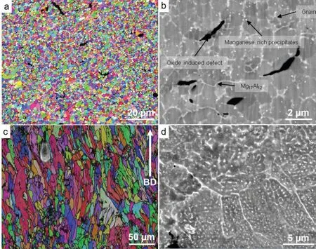
Fig.7.EBSD orientation map and SEM image of LPBF-AZ91 alloy by (a,b) Jauer et al.[30] and (c,d) our unpublished work.
Figs.8b-d demonstrates that although rapid solidificatio of the melt pool produced by the laser beam generates fin equiaxed and columnar grains.The grain growth with a strong[0001]//BD texture results from heat treatment that is caused by the subsequent laser scans throughout the LBPF process.It is shown [34] that grain growth occurs extensively after a single-layer deposition and that the grains reach their ultimate size after the generation of two layers.The detailed mechanism which produces such extensive grain growth and texture development is unknown.However,in Fig.8a [32],such grain growth does not occur.While the composition,size and distribution of the powder particles and the processing were basically identical,the authors proposed that the difference was in the supplier of the powder:Materials Science and Engineering of Werkstoffzentrum Clausthal UG for Fig.8a versus Magnesium Elektron for Fig.8b.However,why the powders from different vendors can result in such a dramatic difference in microstructure is still to be investigated.
The authors proposed that powders from different vendors may contain different amounts of yttrium oxide (Y2O3) particles,which is speculated to provide Zener-pinning to suppress grain growth.In fact,RE early elements have high affini ties to oxygen.The Gibbs free energy of formation of Y2O3and Nd2O3is −1816 and −1807 kJ/mol,respectively,much higher than that of MgO (−596 kJ/mol).Therefore,all the publications about LPBF-WE43 hitherto have shown large amount of RE oxide (Figs.8e and f).Despite high density of RE oxides,the large and basal-orientated grains are still dominant in the LPBF-WE43 reported by Esmaily et al.[11].This observation raises the question about the effectiveness of RE oxide on Zener Pinning of grain growth.
In fact,during solidification the grain growth is more affected by type and concentration of solute atoms,known as Growth Restriction Factor raised by StJohn [49].In this model,the Growth Restriction FactorQ=C0m(k-1)whereC0is the composition,mis the slope of liquidus line,andkis the equilibrium distribution coefficient It can be seen that a higher solute concentration results in a more restriction on grain growth thermodynamically.Therefore,if WE43 powder is significantl oxidised during manufacturing,storage,and transport,the solute concentration of RE element in the powder will be much lower than its designation.The low concentration of solute atoms in powder cannot restrict grains from preferential growth and thus leads to large and basal-orientated grains shown in Figs.8b and c.

Fig.8.EBSD orientation maps show (a) fine equiaxed,and randomly orientated grains in bulk LPBF-WE43 sample [30],(b) fine equiaxed,and randomly orientated grains in the last melt pool and its surrounding large,irregular-shape,and basal-orientated grains [34],and (c) large,irregular-shape,and basalorientated grains in the bulk sample [11].(d and e) EDXS maps acquired from the same material at two different magnifications and (f) XRD spectra showing the presence of various phases including intermetallics and oxygen-rich species in the LPBF-WE43 [11].
Apart from studies based on commercial WE43 powder,a research team from Shanghai Jiaotong University has customised the powder composition and developed severe composition based on Mg-Gd systems[36-38].The as-LPBF Mg-Gd-based alloy shows refine and equiaxed grains (1-2 μm)with random orientations.The alloy contains minimal oxides and pores,and the relative density can be as high as 99.95% [37].The random-orientated equiaxed grains are also achieved by DLD in an Mg-10Gd-3Y-0.4Zr alloy,using a coarser spherical powder (100-300 μm).However,by DLD,the sample has a larger grain size (19 μm in average diameter),and contains a higher fraction of pore [50].Nevertheless,no matter DLD or LPBF is used,the preferential grain growth of basal-orientated grains should be restricted by a high concentration of Gd element (>10 wt.%) during rapid solidification
2.2.4.Mg-Zn-based alloys

Fig.9.(a) Tensile properties of laser additively manufactured Mg alloys against cast alloys [1] and wrought (rolled and extruded) alloys [56].Tensile fracture surface of (b) Mg-9Al [24] and (c) WE43 [32].
Compared with Mg-Al and Mg-RE alloy,Mg-Zn-based alloy has attracted much less attention,despite biocompatibility of Zn.The most important reason is the much poorer ‘printability’ of Mg-Zn alloy than Mg-Al and Mg-RE alloys,as the Mg-Zn has much lower eutectic temperature about 325°C and thus a large solidificatio range.The acceptably low-level of porosity can only be achieved when Zn concentration is very low (e.g.≤1 wt.%) or very high (e.g.≥12 wt.%) [39].However,when the Zn concentration is in the middle,e.g.6 wt.%(the Zn concentration for commercial ZK60 wrought alloy),the sample contains not only a high density of pores,but also severe hot cracking,making the alloy not usable.The highest relative density of ZK60 by LPBF is~97% [41],whilst most of them are lower than 94%.Hence,Zn can only be added as a minor alloying element in laser AM-Mg alloy.
Apart from Mg-Al,Mg-RE,and Mg-Zn-based alloy,Mg-Ca(pre-alloyed powder)[51]and Mg-Sn-based alloy(blended powder) [52] are also investigated.They are expected to have better ‘printability’ than Mg-Zn alloy,as both of them have a higher eutectic temperature(510°C for Mg-Ca and 466°C for Mg-Sn) and narrower solidificatio range than Mg-Zn alloy.The preliminary result looks promising,as both alloys show fin microstructure,but more comprehensive studies need to be provided for understanding the solidificatio behaviour,microstructure evolution,and mechanical and electrochemical properties.
2.3.Properties of laser-based additive manufacturing
2.3.1.Tensile property
The tensile properties of laser additively manufactured Mg alloys are summarised in Table 2 [11,22-39,53-55],and plotted in Fig.9a against cast alloys [1] and wrought (rolled and extruded) alloys [56].The alloy yield strength is above 200 MPa,and some reach 350 MPa,which is sufficien for most structural applications.However,the low ductility is a major issue.Most of AM-Mg alloys have a ductility of less than 5%,and some alloy even does not have any ductility,and their mechanical property has to be measured by compression or hardness test.Such a low ductility is not acceptable as engineering materials.From the characterisation,some alloys have fin grains,weak texture,low porosity,but the ductility is still low.The following reasons are posited.Firstly,the as-LPBF has high residue stress due to the rapid solidification which decreases alloy ductility.Secondly,the studied alloy,such as AZ91,WE43,Mg-Gd alloys,contains a high concentration of alloying elements that form intermetallic along the grain boundaries.Then,the grain boundaries become brittle,becoming the origin of local failure,and they cannot accommodate plastic deformation (e.g.grain boundary sliding,slip and twin transmission across grain boundaries,etc.).Thirdly,the sputtered powder or vapour would re-deposit on the sample surface,causing the part of not well consolidated or with a weak bond.This can be demonstrated by the caulifl wer-like feature on the fracture surface,Fig.9b [24].

Table 2 Input energy density,grain size,tensile,and electrochemical property of laser additively manufactured Mg alloys [11,22-39,53-55].
Up to date,the reported highest ductility of laser additively manufactured Mg alloy is 12.2% in WE43 alloy [32].From the fracture surface (Fig.9c),it is obvious that the sample is fractured in a ductile mode despite some gas pores observed.Annealing at a high temperature can improve alloy ductility.By annealing at 536 °C for 24 h and aged at 205 °C for 48 h,the ductility of LPBF-WE43 is increased from 2.6%in the asbuilt state to 4.3% after heat-treatment [33].A more remarkable increase in ductility from 2.2% to 7.5% is achieved by friction stir processing,which significantl refine grain size,alleviated residue stress,and redistribute the intermetallics of an Mg-10Gd-0.3Zr alloy [36].Although it is unlikely to process a LPBF net shape component by FSP in real engineering applications,it at least demonstrates that the LPBF alloy is not intrinsically brittle,and an acceptable ductility can be obtained if powder quality,composition,and processing are optimised.
2.3.2.Electrochemical durability
Currently,the most promising application of AM Mg alloys is biodegradable implants.Take oral and maxillofacial implants as an example,the implant should maintain mechanical integrity in the firs month,and then gradually degrade and fully dissolved and metabolised after three months.This requires sufficien electrochemical durability as Mg and its alloys is known with poor corrosion resistance in most aqueous environments [57].The electrochemical durability of LPBF pure Mg and some alloys is shown in Table 2
In Hank’s solution,the corrosion current density (icorr) of LPBF pure Mg ranges from 74 -177 μm/cm2[22],which is higher than the cast pure Mg ingot measured under the same condition(23.6 μm/cm2)[58].The mass loss rate is also high,between 3 -32 mm/year,depending on processing parameters.When pure Mg is manufactured by DLD,the corrosion rate is extremely high,about 144 mm/year in 3 wt.% NaCl solution [55].This higher corrosion rate is closely related to the defects generated during LPBF,because the localised corrosion is initiated from the defects and loosely fused Mg clusters and sintered Mg powder are detrimental to the corrosion resistance.High more defects they are,the faster the degradation rate it is [22].
Similarly,the LPBF WE43 alloy also showed much worse corrosion resistance than its cast counterpart.The corrosion current density ranges between 20 -60 μm/cm2in a revised simulated body flui (r-SBF) with 5% foetal bovine serum [59],and in 0.1 M NaCl solution,its mass loss rate(6-7.2 mm/year) is about 6 times higher than that of cast WE43 alloy (0.8-1.2 mm/year) [11].Despite the relative density of more than 99%,the higher corrosion rate is caused by the microgalvanic reaction between the high density of stable RE oxide particles and reactive Mg matrix.The LPBF-WE43 scaffold was reported to lose its structural integrity after 21 days immersion in SBF if the surface is not treated by plasma electrolytic oxidation [60].However,in another report [59],the LPBF-WE43 alloy at least maintained their structural integrity without obvious detachment of degraded particles after 28 days in vitro,but the strength is decreased by 41% compared to that in the as-built state.It seems that the degradation of scaffold is more complex than bulk sample,as it is affected by design parameters,such as pore size and strut diameter.
In contrast,Mg-Al based alloy shows similar corrosion resistance to the cast one.For LPBF-AZ61 alloy,the degradation rate was about 6 -8 mm/year in the as-immersed state,and then decrease and stabilised around 1.2 -2.7 mm/year in SBF [27].This is similar to the cast AZ61 sample in SBF,for which the corrosion rate is about 6.5 mm/year initially and stabilised at 1.299 mm/year after immersion for 24 days[61].
For Mg-Zn system,the LPBF-ZK60 shows slightly better corrosion resistance than cast ZK60 in terms of corrosion current density and hydrogen evolution rate,although the surface of the corroded sample seems to indicate a more severe corrosion of LPBF-ZK60 [62].Shuai et al.added dilute concentration of Cu to LPBF ZK30 [54] and ZK60 [63] to increase the antibacterial effect of Mg-Zn-Zr implant,by blending ZK powders with Cu powders.It is found that the Cu addition accelerates the degradation of LPBF ZK-Cu alloy.
2.3.3.Biocompatibility
As the most promising application of AM-Mg alloys is biodegradable implants,the biocompatibility of LPBF-Mg alloys needs to be considered.Mg is an essential element in the human body.Mg itself biodegradable,and will gradually transfer the load from implant to regenerated bone during degradation[64].They have a comparable density(1.7 g/cm3)and Young’s modulus (~45 GPa) to human bone.Mg is biocompatible and bioactive,significantl promoting cellular proliferation and differentiation [65].It is beneficia to the stabilisation of RNA and DNA,and the healing and bone growth[66,67].However,when developing biodegradable implants based on Mg alloys,the alloying element should be biocompatible as well.For example,although Al addition can enhance the ‘printability’,Al3+is neurotoxic,and it accumulates in the nervous system and may result in Alzheimer’s disease.Similarly,although Cu addition may have some antibacterial effect [54],Cu is most cytotoxic [25].Therefore,Al-and Cu-containing alloys are unlikely to be approved for clinical applications.
So far,numerous studies have reported the biocompatibility of LPBF WE43 as scaffold implant in vitro [59,60,68,69].Live-dead staining with subsequent dual-channel fluorescen optical imaging(FOI)showed a significan percentage of MG-63 cells in direct contactwithWE43 appeared to be dying 4 h after immediate seeding [59].In contrast,any cell death can hardly observed on Ti-6Al-4V 4 h after seeding.The preincubation of WE43 scaffolds for 48 h in physiological serumcontaining culture medium resulted in a substantial number of cells being viable even after 24 h of direct contact.In a separate study using indirect extract-based assays (LDH,XTT and BrdU) method [68],a similar observation of poor cell adherence to LPBF-WE43 scaffold was reported.Although there seems to be no cytotoxic potential deriving from REbased magnesium alloys themselves,the vast reaction of the bare metal surface leads to high values of initial hydrogen gas evolution and local pH shifts,thus impairing cell metabolism[68].In direct live/dead staining,only a few dead cells were identified and no viable cells were observed on the LPBFWE43 scaffold.This issue can be solved by surface modifi cation,such as plasma electrolytic oxidation,because passivating ceramic-like surface not only seems to offer a suitable niche for adhering cells,but also throttled the release of degradation by-products and thus encouraged hardly any signs of cell impairment [60].
Apart from WE43,LPBF scaffold is also reported to be manufacturing based on pre-alloyed Mg-Nd-Zn-Zr (JDBM)[70].Similar to the studies of LPBF-WE43 [59,68],far more cells adhered onto the scaffold coated by dicalcium phosphate dihydrate than onto the uncoated scaffold in the cell adhesion test.In this study [70],no significan difference in terms of cytotoxicity was found between the coated and uncoated LPBF-JDBM scaffold:both samples stimulated cell growth.This findin needs a more comprehensive study and verifica tion because it is highly unlikely that uncoated AM mg will not at least irritate direct cell response.
3.Non-laser-based manufacturing
In this review,we use non-laser-based manufacturing to label the AM method for which the energy sources are not laser.These methods include sinter-based AM,wire arc additive manufacturing (WAAM),friction stir-based additive manufacturing,and indirect AM.Selective electron beam melting,an AM method used for manufacturing Ti and Al components[12],has not been used for AM-Mg alloys,probably becaseu E-beam melting must be done in high vacuum but the Mg evaporates vastly in vacuum.
3.1.Sinter-based additive manufacturing
Unlike fusion-based AM methods which are classifie as a single-step process,sinter-based AM methods are a multistep process where the fina 3D parts are fabricated in two or more distinctive operations.The firs operation step commonly produces an analogous geometry of the fina parts.Then,the analogous geometry consolidates to the fina parts during the subsequent operation step(s).Representative multistep AM processes include binder jetting,material extrusion,material jetting,and vat photopolymerization.In the context of AM technologies for Mg alloys,binder jetting and material extrusion have been realized.While detailed descriptions of these two methods are reviewed in Refs.[71-73],being able to perform AM of 3D parts under ambient conditions shows the greatest promise of binder jetting and material extrusion for AM of Mg alloys.This capability to fabricate 3D parts at room temperature minimize/avoid the issues related to the handling of Mg powder at high temperatures such as safety,oxidation,and evaporation.However,sinter-based AM of Mg is still in the early stage of development and many studies are needed.The advancements made in these two methods will be reviewed in the coming section.
AM of green parts
The firs operation step to form a green 3D part in binder jetting and material extrusion methods involves gluing Mg powder particles together through either an adhesion or a reaction binding mechanism in a layer-by-layer manner.In binder jetting,a liquid binder system is selectively deposited into the powder bed,while in material extrusion methods Mg powder is mixed with a polymeric binder system to produce a feedstock in the form of pellet,filament or paste having an adequate viscosity for extrusion.A binder system is needed only to retain the shape of 3D parts until the sintering process starts and must not adversely affect the consolidation of powder.In view of the intrinsic properties of Mg alloy,the selection of an appropriate binder system for Mg alloy that neither reacts with Mg powder throughout the entire AM process nor leaves any residue behind is essentially important.Due to its high reactivity and low melting temperature,Mg powder reacts with the binder systems that are widely utilised for other materials during feedstock preparations,printing,or subsequent consolidation steps (i.e.,debinding and sintering).These reactions occurring between Mg powder and a binder material or its decompositions by-products lead to the formation of undesired compounds anchored on Mg particle surfaces,strongly inhibiting Mg powder from sintering.For instance,when Mg powder was mixed with PLGA (polylactideco-glycolide) as the binder to prepare a paste feedstock for material extrusion,by-products of PLGA decomposition during the debinding process reacted with Mg powder to form magnesium carboxylate on the surface of Mg powder particles preventing them from sintering [74].
In successful attempts in developing binder systems for material extrusion of AZ91 and AZ 81 alloys powder[75,76],the polymeric binder systems were composed of polypropylene-copolymer-polyethylene,thermoplastic elastomer,and stearic acid that blended with 64 vol.% of the powder mixed at 160 °C to produce feedstock.Solvent debinding in hexane at 40-65 °C for 20-120 h followed by a thermal debinding at higher temperature in a furnace was performed on 3D printed parts to remove the binder systems before sintering process.However,there are no data available about possible binder-Mg powder interaction or its residue.Dong et al.[74] manually mixed up to 62 vol.% of pure Mg powder with a binder system composed of dibutyl phthalate,chloroform,and polystyrene to prepare a paste feedstock.Fourier-transform infrared (FTIR) and XRD analyses of the paste confirme that Mg powder and the binder system did not interact.Thermal decompositions of the binder occured in two temperature ranges of 115-210 °C and 320-440 °C.Analysis of thermal debinded and sintered samples showed that 0.05 wt.% of carbon residue left behind and 1-2 wt.%of MgO formed.
For binder jetting of Mg powder,Su et al.[77] used a mixture of deionized water and multiple low molecular alcoholics for the printing of AZ91D powder that followed by heating of green parts at 90 °C for 10 h in the air to form a net-like framework structure of MgO to maintain the shape of green parts during a sintering process.However,no information on the overall oxygen pick-up in green or sintered parts was provided in this work.It is worth mentioning that a native 10-nm-thick MgO fil inevitably exists on the outermost layer of Mg powder [78].This fil could be thickened because Mg powder reacts with an aqueous-based solution[79].A thicker MgO fil makes the subsequent sintering process more difficult which is thoroughly discussed in the next section.Salehi et al.[80-82] developed a capillary-mediated bridging concept for binder jetting of pure Mg and Mg-Zn-Zr powder to eliminate the need for a polymeric binder system and subsequent debinding step.This method functions based on the reaction binding mechanism in which the native MgO fil on Mg powder particles interacts with a proprietary solution to form interparticle bridges of MgCO3•3H2O(Fig.10a).These bridges completely decomposed to MgO at around 400 °C in a sintering step,according to thermal and chemical analyses results.Figs.10b and c show that the morphology and chemical composition of starting Mg powder in terms of carbon,hydrogen and oxygen elements changed in green parts,and when the amount of solution used for binder jetting increased,more reactions and,in turn,more compositional changes occurred.Sintering retrieved the primary composition of raw powder from green parts with zero contamination left behind.It should be emphasized that since AM of Mg should be mainly focussing on biomedical applications,these approaches have the great risk of leaving any substance behind from the binding phase -which essentially is a great risk for this field
Sintering of green parts
Consolidation of green parts,the secondary operation step in sintered-based AM,is mainly composed of debinding and sintering stages.Currently,densificatio of green Mg parts is a major issue in sinter-based AM of Mg alloys.Densifi cation is affected by the interplay of several parameters,including;(i) properties of starting Mg powder (e.g.chemical composition,powder particle size,powder shape,particle size distribution,powder fl wabiltiy,oxygen content),(ii) process parameters for AM of green Mg parts(e.g.Mg powder-binder interactions,layer thickness,binder saturation level,density),and (iii) debinding and sintering parameters (e.g.debinding residue,sintering furnace type,sintering temperature,sintering time,sintering atmosphere).
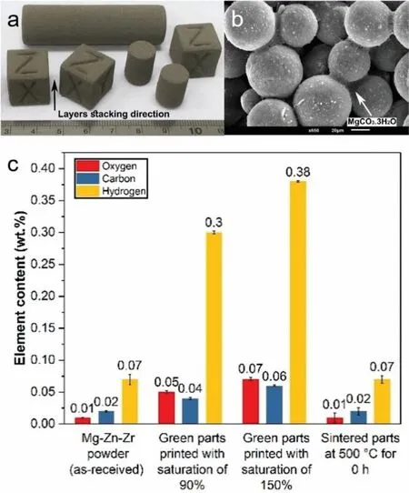
Fig.10.Binder jetting of Mg-Zn-Zr powder by capillary-mediated bridging,(a) macrograph of green parts printed with layer thickness of 100 μm and solution saturation level of 70%,(b) solid interparticle bridges in green parts that enabled the rapid 3D assembly of Mg powder particles,(c) chemical analysis of raw Mg-Zn-Zr powder,green parts and sintered parts showed zero-sum change in chemical compositions of the raw in the sintered samples [80].
As discussed earlier,a proper choice of binder systems for Mg powder that remains the powder particle surfaces intact is vital for successful sintering.Carbon residue on Mg particle surface has a severely inhibiting effect on sintering [83].The native MgO shell on the outside of each Mg powder wholly retards solid-state sintering of a loosely packed configuratio of powder in green Mg parts since MgO is nearly impervious to the diffusion of Mg atoms as discussed in Ref.[82].As MgO is rather stable even beyond Mg boiling temperature,the oxide shell must be broken or reduced to provide a diffusion path for Mg atoms and feasible sintering kinetics.Powder compactions and the addition of more reactive elements like calcium to Mg powder were used in convectional powder metallurgy of Mg alloys to overcome this issue[84].Since applying an external mechanical force on green Mg parts is not possible,liquid phase sintering was used to partially break the MgO shell and densify green Mg parts fabricated by binder jetting and material extrusion methods[72,74,77,80,82].In the liquid phase sintering,the capillary force draws the forming liquid into the sintered neck regions between adjacent powder particles for enhanced mass transport amongst particles.In general,a higher sintering temperature or liquid phase content results in a higher density and,in turn,greater properties in sintered Mg parts.However,swelling phenomena constraints the sintering temperatures and liquid phase fractions from rising to a greater range to achieve a higher density and a shorter sintering dwell time.Due to high surface tension of molten Mg and poor wettability between MgO and liquid Mg phase,when the relative fraction of liquid phase goes beyond the capability of capillary force,excess liquid phase pulls out to the exterior of Mg parts to form nodules on sintered parts,as observed in sintering of binder jet printed Mg-Zn-Zr alloy and extrusion-based printed pure Mg alloy [74,80,82].This swelling causes the part shape fidelit to lose and it’s chemical composition to degrade.

Fig.11.Pushing the sintering innovation boundaries toward a higher density in binder jet printed Mg components while maintaining their shape fidel ty and chemical composition during the post-printing sintering process,(a) cuboid samples made of Mg-Zn-Zr powder sintered at the maximum temperature of 625 °C,and (b) spherical cap-like samples sintered made from the same Mg-Zn-Zr powder sintered at the maximum temperatures of 606 °C and 615 °C showing uniform shrinkage and no swelling during the sintering process [85].
Three attempts have been made so far to enhance densificatio and shorten the sintering time of binder jet-printed Mg parts,and many more studies are needed to advance sintering knowledge for Mg alloy.A recent study reported that binder jet printed green Mg parts could be successfully sintered up to 50 °C above the swelling temperature previously known for an alloy without the addition of sintering aids if the dihedral angle between adjacent Mg powder particles over the course of the sintering process is meticulously controlled [85].Fig.11 shows how the shape fidelit of binder jet printed Mg-Zn-Zr components was maintained in a broad range of sintering temperatures.It is worth mentioning that the swelling temperature previously reported for this alloy was 573 °C [82] while the parts sintered in a broad range of sintering temperatures up to 625 °C to obtain a higher density.In the second attempt,Salehi et al.[72,80] found that employing microwave sintering for densificatio of binder jet printed Mg-Zr-Zn green parts shortened the sintering time by three folds as compared to sintering in a conventional tube furnace because sintering mechanisms triggered at a comparatively lower temperature in a microwave furnace.Although the notion of microwave sintering is clear,further research into some challenges appertaining to AM is needed.For instance,green parts with more complex geometries are generally embedded in refractory powder to have adequate supports during sintering at elevated temperatures.The presence of this support powder would totally change electromagnetic energy absorptions in a microwave furnace.In the third attempt,Su et al.[77] used a two-step sintering process in which a binder jet-printed AZ91D sample was firs heated up to 700 °C,held for 30 min,rapidly cooled to lower temperature at around 600 °C,and held for 6 h Even though a density level of 99%was obtained for small cylindrical samples,more comprehensive studies need to be performed because sintering above a liquidus temperature involves a high risk of losing shape fi delity and even a total collapse of green parts,especially for a larger part with more complex geometries.
Alloy systems investigated
The firs work regarding the sinter-based method was achieved in pure Mg and Mg-Zr-Zn by Salehi et al.from the National University of Singapore and Singapore Institute of Manufacturing Technology in 2018,whereby the capillarymediated bridging concept was used for binder jetting,as discussed above [81].In 2019,Wolf et al.from Helmholtz-Zentrum Geesthacht,Germany,reported the firs Mg samples produced by material extrusion whereby they capitalized on their experience in developing Mg metal injection moulding for fused filamen fabrication of AZ81 [75].Compared to laser-based methods for AM of Mg,very few compositions have been investigated for sinter-based methods.Only four compositions have been developed by either binder jetting or material extrusion methods,namely,pure Mg,Mg-Zn-Zr (a similar composition to the ZK60A alloy),AZ91,AZ81,predominantly due to the challenges associated with developing green parts feedstock technology and subsequent consolidation strategies,as thoroughly discussed above.These types of powder had spherical shapes and their sizes were in the range of 25 to 70 μm,which were supplied by commercial Mg powder manufacturers.Interestingly,Mg-Zn-based alloys with 5.5 wt.% Zn,which indicated poor printability for LPBF(See Section 2.2.4),have gained attention for sinter-based AM as a result of their broad solidificatio range making them desirable for liquid phase sintering.
3.2.Properties of sinter-based additive manufacturing
Density and microstructure
The relative density (Dens.) and corresponding sintering regimes of sinter-based AM Mg alloys are summarised in Table 3.Density increases with increasing sintering temperature and/or time for all alloys as a result of improved mass transports amongst adjacent Mg powder particles,in agreement with conventional powder metallurgy.Up to date,the reported highest density of sinter-based additively manufactured Mg alloy is 99.5% in AZ91 alloy [77].Comparison made between the reported sintering temperatures and the solidificatio temperature ranges of the alloys (i.e.,solidus and liquidus temperatures) indicated that liquid phase sintering was used for sintering all alloys and the selected sintering temperature was close or even above the liquidus temperature of alloys.Such a high amount of liquid content in green parts could be challenging when it comes to translating results from small samples to a large component because the optimal fraction of liquid phase for sintering of powder metallurgy fabricated parts was in the range of 20 vol.% to 40 vol.%[86].To address this concern,results on shrinkage and distortion analysis of sinter-based AM fabricated Mg need to be reported.
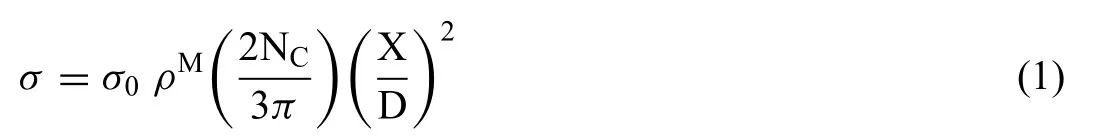
Microstructural features of sinter-based AM are more similar to conventional powder metallurgy.Fig.12 shows EBSD of binder jet printed AZ91 samples after liquid phase sintering at different temperatures with the corresponding grain size.As can be seen,liquid phase sintering profile control microstructures and the average grain sizes are extremely larger than that of LPBF (Table 2).This grain growth seems to be inevitable since a higher sintering temperature and an extended dwell time are required to densify green Mg parts.It should be noted that the density of a green Mg part is usually around 50% and is lower than tap density (i.e.,the tightest packing configuratio of a loosely packed powder) of starting raw Mg powder [82].
Porosity and biocompatibility
Sinter-based AM provides unique opportunities for the fabrication of interconnected porous Mg scaffolds.In addition to a larger pore designed in a CAD fil (pores by design),smaller interconnected pores are formed at interparticle spaces in green/brown parts (pores by process).The size and distribution of these micropores are controlled by printing parameters and sintering processes [71].Such a hierarchical and interconnected pore structure of micropores and macropores has a great potential for tissue engineering.Median pore diameter~15 μm and pore openness~95% were reported in binder jet printed Mg parts after sintering to relative density 71% [72,82].This value is in the size range of bone osteocyte cells (10 to 15μm) [87].Indirect and direct culture assays with preosteoblasts on porous Mg scaffolds fabricated by material extrusion and coated with MgF2-CaP indicated numerous cells attached to the scaffold surfaces and the level 0 cytotoxicity requirement [88].
Chemical composition and mechanical properties
Process-induced change in chemical composition due to the evaporation of alloying elements and/or Mg matrix is less severe in sinter-based AM as compared to LPBF because the maximum temperature is limited to the sintering temperature.The overall chemical composition is governed by the choice of sintering parameters,especially sintering temperature.The evaporation of alloying elements occurred in binder jet-printed Mg-5.5Zn-0.15Zr after sintering at 573 °C and 615 °C were 1.1% and 6% [89],whereas 18-22% compositional change was reported in LPBF of Mg-Zn-Zr alloys [40,41].
The mechanical properties of sinter-based Mg alloys are summarized in Table 3.Tensile properties obtained are low and insufficient Strength increases at higher sintering temperatures and density as the general trend for variation of mechanical properties in Table 3.Amongst many other factors governing strength (e.g.,composition and grain size),density and pores features play major parts on obtained mechanical properties of sinter-based manufacturing technologies.Pores in sintered samples not only lead to a reduction in the load-bearing area but also cause local stress concentrations for crack initiation and propagation.In powder metallurgy fabricated parts fracture under mechanical load is favoured by a path thorough the sinter necks and therefore strength of sintered samples can be still lower for a higher density.The following equation is established to correlate strength with porosity and sinter neck size in powder metallurgy[86]:

Table 3 Sintering condition,density,tensile,compressive and electrochemical property of sinter-based additively manufactured Mg alloys.
whereσis the strength of a sintered sample,σ0is the strength of a fully dense material,ρis the relative density of a sintered sample,M is a proportionality constant (e.g.,2.5-6 for Al),NCis the mean coordination number of particles (depends on density),X is the diameter of sinter necks,and D is powder particle diameter.As can be seen from the equation,the strength of a sintered sample is proportional to density to the power of M,and the factor 2/3 indicates stress concentration and the preference for facture to happen at sinter necks.
In general,tensile properties of sinter-based AM samples are expected to be lower as compared to LPBF (Table 2)predominantly due to a lower density.However,sinter-based AM methods can result in a higher tensile property for the alloys with poor LPBF’s printability(e.g.,Mg-Zn-based alloys).As-sintered AZ91 specimens fabricated by material extrusion(Table 3) showed much lower yield and tensile strength than those fabricated by LPBF (Table 2).SEM micrograph of the fracture surface under tensile loading indicated that fracture occurred along MgO layer boundaries leads to brittle fracture and low ductility of 2.4%−2.8% [6].When it comes to Mg-Zn alloys,the tensile properties obtained in binder jet printed Mg-5.5Zn-0.2Zr alloy exceeded the values reported for laseradditively manufactured Mg-Zn alloy [39] while fell in the range of as-cast alloys with similar chemical compositions[85].
Electrochemical properties
Table 3 displays the electrochemical durability of sinterbased additively manufactured Mg alloys.The obtained corrosion rates are higher than the rates for as-cast or rolled counterparts.The post-corrosion X-ray computed tomography micrographs of binder jet printed Mg-Zn-Zr samples in phosphate-buffered saline (PBS) show nonuniform corrosion occurred within the porous structures of binder jet printed samples as compared to the as-cast counterpart (Fig.13a).Electrochemical analysis indicated the corrosion resistance is closely associated with sintering regimes.Corrosion rate generally increases with increasing porosity percentage of sintered samples due to larger surface areas and possible crevices[89].In addition,microstructural factors such as a segregated MgO fil along the sinter necks and non-uniform distribution of alloying elements contributed to higher corrosion rates of as-sintered samples [77,89].
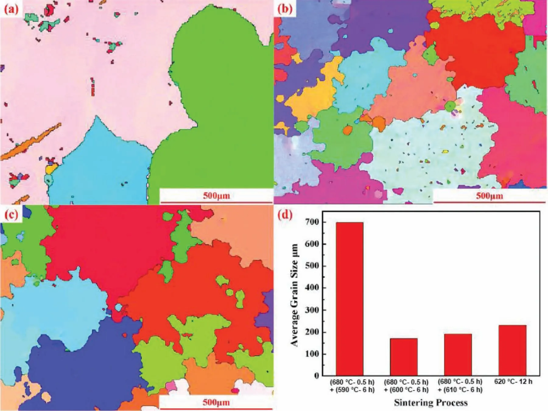
Fig.12.EBSD orientation map of binder jet-printed AZ91 samples in different sintering profiles (a) sintered at 680 °C for 0.5 h followed by sintering at 590 °C for 6 h (TTS-4),(b) sintered at 680 °C for 0.5 h followed by sintering at 600 °C for 6 h;(c) sintered at 680 °C for 0.5 h followed by sintering at 610 °C for 6 h (TTS-5),(d) the corresponding average grain size for different sintering profile [77].
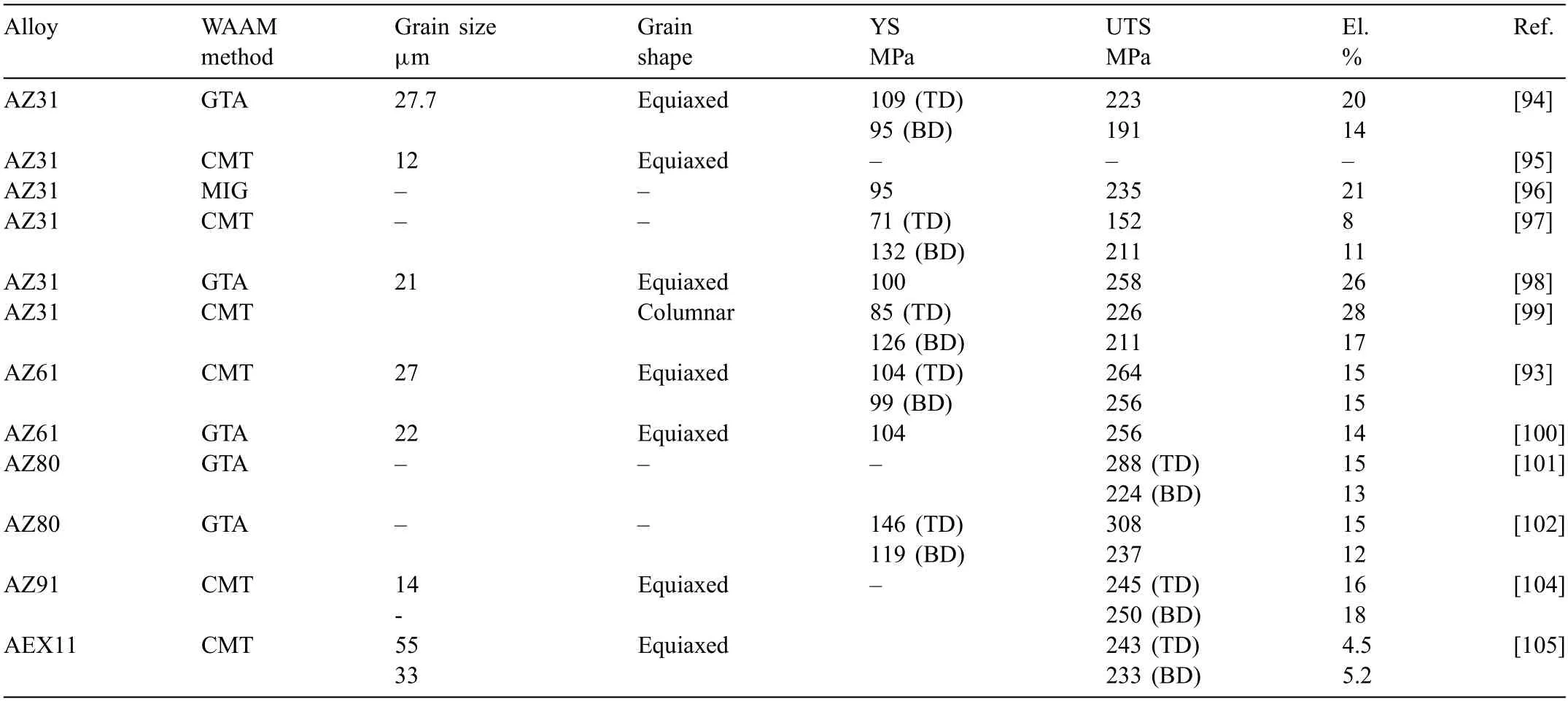
Table 4 Composition,grain size and shape,and tensile property of WAAM-Mg alloys.

Fig.13.Corrosion behaviour of sinter-based AM Mg alloys,(a) X-ray computed tomography micrographs of binder jet printed Mg-5.5Zn-0.2Zr and as-cast samples after 5 h immersion in PBS at 37 °C,and (b) in vitro degradation of extrusion-based printed scaffolds made of pure Mg and the surface modifie scaffold in revised simulated body flui [88,89].
Surface modificatio of sinter-based additively manufactured Mg alloys shows a great promise in retarding the corrosion rate,especially for biomedical applications.An ideal bone substitute is expected to have biodegradation in the range of 0.2 to 0.5 mmy−1[90].As can be seen in Table 3,in vitro degradation rate of extrusion-based printed pure Mg alloy is about 2.2 mmy−1,which is higher than those ascast (0.84 mmy−1) and rolled pure Mg (1.94 mmy−1)counterparts,and therefore the scaffolds virtually degraded in a day (Fig.13b) [88].Applying single or double-layer coatings reduced the corrosion rate to 1.4 and 0.2 mmy−1to protect the porous scaffolds from rapid corrosion (Fig.13b)such that in vitro immersion tests of up to 7 days were comparable with those of the trabecular bone [88].However,it should be noted that the coating here only works with chemical conversion coatings as Mg-F.Deposition coatings might not work due to the macroporosity and generally a cracked and highly porous surface bears potential worsening of the degradation resistance when using other kinds of coatings as PEO (no homogenous surface layer).
3.3.Wire arc additive manufacturing (WAAM)
Different to the laser-based or sinter-based AM where Mg alloy powder is the feedstock materials,wire arc additive manufacturing (WAAM) uses Mg alloy wire as the feed stock materials.WAAM originates from wire arc welding,utilizes the arc welding process (including gas metal arc welding,gas tungsten arc welding,and plasma arc welding) to manufacture metal parts in a layer-by-layer manner[91,92].Compared with LPBF,it allows producing components with a high deposition rate,low equipment cost,high material utilization,and consequent environmental friendliness.Due to the existence of a local gas shielding provided by the welding gun,working inside a chamber is not necessary.Thus,there are practically no limitations in part size.Because Mg wire,rather than Mg powder,is used for AM,the safety risks associated with handling Mg powders do not exist.Moreover,the Mg alloy fila ments are produced by wire drawing rather than atomisation.This can significantl reduce the cost of feedstock materials production,transport,storage,and others associated with powder management.
Currently,cold-metal-transfer (CMT) is the most suitable technique for WAAM of Mg alloy,due to the lower heat output.Because Mg alloy has a low melting point and evaporation point,the WAAM based on MIG and TIG welding are not suitable due to excessive heat output,leading to wrap and melt back.The big difference between CMT and TIG/MIG is in the wire feed.Rather than continuously moving forward into the weld pool,with CMT,the wire is retracted as the instant current fl ws.An automated WAAM-CMT system brings the Mg alloy wire into and out of contact with the weld pool many times per second.Because it uses a pulsing action instead of a continuous stream of power,CMT welding generates only one-tenth of the heat that MIG welding does.
A WAAM system includes a path simulation software,data communication lines,welding power supply,wire feed system and execution actuator.The metal parts are manufactured mainly relying on repeated positioning of the displacement,speed and position of the execution actuator,to realize repeated reproduction of the molten pool by the point-by-point control on line,surface and body.Furthermore,there are a number of factors directly affecting the dimensional accuracy of the forming parts such as the accuracy and stability of the execution actuator,the key technological parameters,mode of welding and the stability of arc heat sources.With respect to the processing conditions,the mean wire feed rate corresponds to the rate of electrode consumption.Current and voltage values are characteristic for determining the energy input.The deposition rate (DR) of WAAM can be expressed by the equation below

Whereρis the density of feedstock alloy (1.73 g/cm3for Mg),is the mean wire feed speed,and Awwis the weld wire cross-sectional area [93].
Despite their advantages,wire-based processes for magnesium are relatively uncommon to date,not least due to insufficien fille wire availability.The number of published results of MgWAAM is very small.To the best of our knowledge,the most papers reported commercial Mg-Al-Zn-based WAAM,including AZ31 [94-99],AZ61 [93,100],AZ80 [101-103],AZ91 [104],and AEX11 [105].The commercial grades are generally used as all-purpose wires for magnesium welding,where the fille wire is selected to best fi the base material composition,rather than specificall designed for welding or additive layer manufacturing purposes.
Fig.14a shows an AZ31 block fabricated by WAAM.Much higher surface roughness and lower dimensional accuracy than the powder-based AM methods.A post-WAAM machining and surface finishin should be applied before the WAAM component can be used.This should restrict its applications in the industry.Fig.14b shows the processing window for AZ31 alloy,the most commonly used commercial composition.In a single track experiment,it is found that the welding current (energy input) has a significan impact,and a bead shape could not be obtained under low welding currents (60 A herein).This is because,in the semiautomatic or automatic welding (WAAM) process,the wire feed rate decreases with the decreasing current.Therefore,under a low welding current,the amount of wire supplied was insufficient and intermitted bead occurs.Under high torch feed speed,humping,as a welding defect,occurs.A humping bead becomes periodically undulated and irregular surface beads develop [106,107].To prevent humping,it is necessary to lower the torch feed speed [108] to a value less than 1000 mm/min.Under proper WAAM parameters,an extremely low porosity can be achieved,about 0.00025% (measured by μCT)[96] and 5 × 10⁻⁵mm3[100].
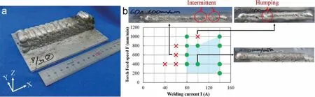
Fig.14.(a) Photo of WAAM fabricated object,and (b) effect of welding current and torch feed speed on welding defects [96].
The microstructure of alloy manufactured by WAAM is affected by processing conditions.Both columnar and equiaxed grains are reported,and the grain size,shape and mechanical properties are summarised in Table 4.It is found that the ductility of alloy fabricated by WAAM is much higher than the alloys by powder-based AM methods.Whilst the total elongation of LPBF-AZ91 is nearly negligible (shown in Table 2),the WAAM-AZ91 has a total elongation of 16-18%[104].
Compared with LBPF,the major drawbacks of WAAM-Mg include that Scaffold structures possible might be too coarse for applications in medical,availability of wire (no custom alloys) and finall the processing is still very sophisticated(Mg can only be welded by AC etc.).Furthermore,it is not as easy as it might seem at the beginning (comparable to welding of Mg in general).
3.4.Friction stir-based additive manufacturing
Friction stir-based AM is a solid-state technique founded on a well-established process of friction stir welding to additively manufacture large-scale near-net-shaped components.According to materials supply procedures to perform the layer-by-layer joining,friction stir-based AM is broadly classifie into two methods,namely friction stir additive manufacturing (FSAM) and additive friction stir deposition (AFSD).In FSAM,multiple plates are welded on top of one another by using a non-consumable rotating tool with a designed pin and shoulder.The plates are bonded together like a multilayersandwich structure until the desired height is reached.In AFSD,feed materials in the form of powder or solid rods continually push to the stirring zone through a non-consumable hollow cylindrical tool.The frictional heat generated at the interface between the workpiece (i.e.,a substrate plate) and the rotating tool softens the feed material that is then plastically deformed,shaped,and bonded to the workpiece by the tool path travelling.This process is repeated to deposit the feedstock material layer-by-layer.Detailed characteristics of friction-stir-based AM methods in terms of tooling,design strategies,and obtainable materials properties have been thoroughly reviewed in Refs.[109-112].Being a solid-state process that could render a fully dense structure with relatively fin and equiaxed microstructures are the salient benefit of friction stir-based AM methods for Mg alloys,while the inability to fabricate complex geometries,spatial resolution and geometric precision are their major drawbacks.The minimum layer thickness reported in the literature for Mg alloys is about 500 μm which is obtained by the AFSD method (Table 5).Results indicated that Mg layers deposited with optimized process parameters are fully dense inside the stir zone,but some mass flas still forms on the edges of tool paths that need to be removed by a secondary manufacturing process.The integration of friction stir-based AM with a secondary subtractive method could form a hybrid additive manufacturing to enable more precise control of the finishin quality and macroscopic shape of additively manufactured Mg parts.The status quo and current trends of hybrid additive manufacturing are reviewed elsewhere [113,114].

Table 5 Process parameters,grain size,hardness,and tensile properties of friction stir-based additively manufactured Mg alloys.
Operating processing windows in friction-stir-based methods are controlled by process parameters such as tool rotational speed,tool traverse speed,tool plunge depth,tool geometries,and feed rate.The interplay of these parameters determines heat input generated in the stir zone.Inadequate or excessive heat input leads to the formation of defects.Friction stir processes typically operate at a temperature in the range of 0.6 to 0.9 melting temperature of materials.It is demonstrated that defect-free structures can be obtained through operating temperatures between 0.8 and 0.9 of the solidus temperature of Mg alloys [115,116].Currently,friction stir-based AM of Mg alloys perform in atmospheric conditions and thus slight oxidation,especially at layer interfaces,takes place.Conducting the build process in an inert atmosphere could mitigate this oxidation issue.
The earliest trial of friction stir-based AM of Mg alloys is reported by Palanivel et al.from the University of North Texas in 2014 whereby the FSAM method was used to join four layers of 1.7-mm thick sheets [115].Since then,four other Mg alloys,namely AZ31,E675,AMX602,E21 have been developed by either the FSAM or AFSD method[117-121].It should be noted that the freedom of design for friction stir-based additive manufacturing is extremely limited.
Microstructure
In general,the microstructure of friction-stir-based processes can be divided into three distinct regions by their thermomechanical features,namely the stir zone,thermomechanically affected zone,and heat-affected zone.These regions stem from temperature gradient and spatial nature of strain and strain rate distribution while the rotating tool is interacting with the workpiece,as comprehensively reviewed in Refs [122,123].Such a different thermal and deformation history over the spatial scale means that microstructure and composition vary with position,especially for alloys rich in alloying elements.More complexity in microstructural evolutions arises in friction stir-based AM methods due to the fact that the previously deposited layers are exposed to additional deformation and thermal cycles while depositing each subsequent layer.Formations of banding microstructure and Zr rich-clusters segregation originated from spatial dependence of thermomechanical conditions were observed in FSAM of WE43 alloy [115].Fig.15 displays EBSD inverse pole fig ure maps for four layers of WE43 alloy built by the FSAM method,depicting variations in the grain size along with the height of the build.While the entire stir zone (Fig.15a and c) is composed of refine equiaxed grains as a result of dynamic recrystallization,each deposited layer creates a thermomechanically affected zone and a heat-affected zone in the layer beneath it.Fig.15b shows the sandwiched microstructure at the interface of a layer which consists of three regions:Coarser grains on top,fine grains with more uniform distribution in the middle,and very fin submicron-sized grains at the bottom.Such a microstructural evolution at the interface is tied to the spatial nature of deformation and temperature along the build direction.However,the exact mechanism is still not understood,but should significantl decrease the corrosion resistance.Fig.15d shows a necklace-type structure in the thermomechanically affected zone depicting the recrystallization occurrence at grain boundaries.A similar trend towards changing grain size along the build direction from the top to bottom of deposited layers was reported in WE43 alloy built by the AFSD method [117].Such a microstructural variation leads to property inhomogeneity and adversely affects the strength and fatigue performance of friction stir-based additive manufactured Mg alloys [119,120].It should be noted that post-build heat treatment would reduce most of this microstructural inhomogeneity which is an avenue for further studies.
Table 5 summarizes grain sizes of friction sir-based additively manufactured Mg alloys.Drawing an analogy between these values and the corresponding grain sizes of Mg alloys primarily utilized as plates or feed materials for friction-based AM indicated a significan grain size refinemen along with the formation of more equiaxed and uniform grains distribution after deposition from a coarser-grained feedstock.Comparing Table 5 and Table 5 imply that the grain sizes achieved through both FSAM and AFSD methods fall in the range obtained by LPBF of Mg alloys.
Mechanical properties
Fig.16a shows defect-free and well consolidated 68 layers of WE43 alloy built by the AFSD method.Fig.16b depicts its cross-sectional microhardness profil along the build direction together with corresponding EBSD maps for the selected locations.The microhardness profil varies from the top to the bottom of the build direction,which is in line with grain size variations.This variation is associated with the spatial change of plastic deformation and thermal cycles that occurred during the build process,as discussed in the previous section.Table 4 summarises hardness and tensile properties of friction stir additively manufactured alloys.WE43 built by friction-stir-based methods display superior mechanical properties than those reported for as-cast WE43 (YS=137 MPa,UTS=217 MPa,and EL.=8.2% [124]) which is mainly originated from its remarkably fine grain size.Similar trends from the hardness values comparing the friction-stirbased methods to conventionally fabricated counterparts are observed.When compared to WE43 LBPF (Table 2),friction stir-based additively manufactured WE43 has almost similar values for YS and UTS while its ductility is significantl higher due to greater density and more equiaxed grain microstructure.For AZ31 built by friction-stir-based methods,the tensile strength and ductility is close to AZ31 in asextruded or as-rolled conditions.The yield strength is more dependant on the method and process parameters used since AZ31 is a work-hardened alloy.Table 4 also signifie the anisotropic mechanical properties of the built alloys with respect to the direction,which is likely due to the strong crystallographic texture dependence of Mg or manufacturing issues(e.g.,oxidation).More investigation is needed to understand texture developments and anisotropy of friction stir-based additively manufactured Mg alloys.

Fig.16.Additive friction stir deposition of WE43 alloy,(a) macroscopic image of the deposit consisting of total 68 layers which was deposited with optimized process parameters to achieve full density and minimal surface defects (mass flash on the edges of tool paths,and (b) hardness profil from the bottom to the top of the deposit along the build direction,and (c-e) EBSD orientation maps of the selected locations near the top,middle,and bottom part of the deposit.Adapted from [119].
3.5.Indirect additive manufacturing
This technique is essentially casting of molten metals into additively manufactured moulds.Sodium chloride (NaCl) has been established as a mould material for indirect AM of Mg alloys since no chemical reaction was reported between NaCl and molten Mg alloys,and NaCl moulds can readily be removed by a subsequent leaching step to obtain Mg parts[125,126].As the earliest trial for indirect AM of Mg alloys,Staiger et al.[127] used a two-step process to fabricate NaCl mould by infiltratin NaCl paste into an additively manufactured polymeric template that was then burnt out to leave an NaCl mould behind.Kleger et al.[126] used direct ink writing,an extrusion-based AM method,to directly fabricate a NaCl mould.The fabricated NaCl moulds were then sintered at around 690 °C to gain adequate mechanical integrity before being infiltrate with liquid Mg at around 700 °C.Finally,NaCl moulds were removed by leaching in an aqueous NaOH solution under ambient conditions.

Fig.17.Macrographs of the process fl w for indirect additive manufacturing of a Mg scaffold at different stages,which include fabricating a NaCl mould via direct ink writing,sintering the mould,infiltratin the mould with liquid Mg,and leaching the mould to obtain the Mg scaffold.Adapted from [126].
The firs work of indirect 3D AM was achieved in pure Mg in 2010 [127].Since then,very few studies have been conducted to develop this method [125-129].All researchers to date have focused on the fabrication of Mg scaffolds with structured porosity made of pure Mg and their investigations were primarily concerned about determining processing window for the fabrication of a mould and its infiltratio with Mg melt via pressure or vacuum-assisted casting processes.Currently,indirect AM capabilities for Mg alloys were found to be constrained by the precision of NaCl moulds fabrication rather than by the infiltratio of molten Mg [126,129].The process is shown in Fig.17.Given that>95% of Mg alloy products are made by casting techniques,indirect AM of Mg alloys could potentially have a distinct advantage over the other AM methods in terms of high build rates,good scalability,and industrial adaptions.To push its potential further,indirect AM of Mg would integrate with a subtractive manufacturing method to bring a hybrid AM solution for producing complex geometries with geometric precision.However,the main drawback of this method is that chloride is the major driver in Mg corrosion,and thus this approach is not widely used due to the corrosion attack of the NaCl on the mould.
4.Summary
The above review and discussion have summarised the critical facets related to the principal methods of AM in the production of Mg-alloys.What is evident,is that there have now been broad attempts,from wholly independent research groups,resulting in successfully prepared AM Mgalloys.Of the methods utilised,Laser Powder Bed Fusion(LPBF),Wire arc additive manufacturing (WAAM) and Friction Stir Additive manufacturing (FSAM) -all have demonstrated that they are capable of producing Mg-alloys via AM.In terms of a mini-summary:LPBF demonstrated the prospect of high dimensional tolerance,a range of alloys,satisfactory strength,albeit limited ductility;WAAM demonstrated moderate strength,however with appreciable ductility possible;and FSAM also demonstrated moderate strength,also with appreciable ductility possible.
Of the methods presented,the fina application will be relevant to the selection of production route.For example,it would appear based on the works reviewed herein,that most methods (with the exception of LPBF) are not suitable for biomedical application.Conversely,LPBF is limited in the dimension of components that may be produced.However,what is clear is that the prospects of AM Mg-alloys are vast,and the potential to realise the opportunities raised in the Introduction herein are all possible (net shape,diverse alloy compositions,complex designs,customisation,etc.).However,what this review has also made abundantly clear,is that a number of open research questions remain,and that there has been no (single,or communal) attempt thus far,at answering such questions.An example of such open questions (in no particular hierarchy) is whether or not ductility of AM Mgalloys is adversely impacted by dislocation density or residual stress? Has dislocation density been studied appropriately in AM Mg-alloys -and how would properties be compared with other hexagonal alloys,such as Ti-alloys? What would the solidificatio of AM Mg-alloys from LPBF resemble in the context that there is always some evaporation occurring?etc.
This review has also indicated,that it is difficul to systematically review the fiel in terms of mechanistic comparisions,since the most significan ‘ingredient’in AM Mg-alloys is the powder used for fabrication,and,a direct (mechanistic) comparison between all studies would need to be reliant on reproducible powder properties.Embedded within a number of the studies reviewed,the variation in powder properties (in addition to powder supplier,size,storage,etc.) varied.Additionally,the properties measured for similar alloys,was also rather variable between diverse studied.Therefore,a future research suggestion is (perhaps similar to the situation in other alloy systems prepared by AM) is that systematic research should be conducted in the following areas,treating each such area as a variable,namely in:(i) Raw materials,(ii) storage conditions,(iii) process parameters,(iv) heat treatment,and (v) coatings and surface finishing
In terms of a concise summary,based on the review herein,the challenges and prospects that present themselves are compiled below.
4.1.Challenges
•In the case of laser-based AM,the requisite production of pre-alloyed powder is a challenge.However,evidence suggests that blending of elemental and a mixture of prealloyed powders is suitable.Investigation in the domain of Mg powder blending,and build consistency,merits further study.
•Mechanistic studies are still required to understand the physical properties of AM prepared Mg alloys.Certainly,laser prepared AM alloys to demonstrate properties that are different from non-AM Mg alloys,and the physical nature of these differences is a green fiel (i.e.impact of AM on strengthening mechanisms,and adverse impact of AM on ductility).If LPBF AM Mg alloys can have appreciable ductility,this will generate significan and immediate interest -as it would also solve one of the major challenges in existing (non AM) Mg-alloys.
•Health and safety are a constant concern with Mg and its alloys.Whilst the safety aspect of Mg-alloy production is also the key priority and critical in the production of any Mg-based materials (including conventional casting which must be carried out in well-controlled environments by expert personnel),in the case of AM-Mg,this also includes:◦Always using the minimum viable volume of powder
◦Safe powder handling and safe storage away from any ignition source (and minimising exposure to atmospheric conditions)
◦Appropriate,and monitored,environment control in any production and processing steps.
◦Precautions to control any non-self-extinguishing scenarios (including engineering controls for the avoidance of ignition,and,robust and reliable extinguishing methods that are always capable of managing volumes of material being used).The volume of powder being used for any build,or in the vicinity of a build,should always be below the extinguishing capability available.
•Recycling of used Mg-alloy powder has not been explored to date.
•Process-induced compositional changes have not been explored to date.
•In general,sinter-based AM is relatively less advanced as compared to LPBF for Mg-alloys,owing in part to the limited studies to date.The niche of sinter-based AM is however distinct.In recent years,binder jetting is one of the major AM technologies suitable for production has been growing rapidly.Accordingly,binder jetting of Mg would be able to expand at a faster pace -but remains nascent.The preliminary results for sinter-based AM of Mg alloy indicate that more comprehensive research is required to provide insight into understanding the printing and sintering behaviour,microstructural evolution,chemical,mechanical and electrochemical properties.
•Post-processing of AM fabricated Mg alloys has not been explored in any detail,similarly,value adding processes -such as,for example,achieving a uniform coating upon porous scaffolds of Mg-alloys.
4.2.Prospects
•There are significan prospects for the investigation of new Mg-alloys.This includes at a minimum:(i) extended solubility limits,and (ii) exploration of previously insoluble elements (that includes transition metals).
•The realisation of directly produced thin-walled components.
•Complex structures that can provide‘properties by design’.This includes truss structures that may provide extended total ductility (i.e.by the summation of smaller deflection resulting in a larger overall deflection)
•Ultra-lightweight components,that utilise free space as a design variable.The total density of a component including free space can be<<1 g/cm3).As with any new development in this context,it would increase the usage base as the materials properties evolve to serve alternative markets.
•Devices and smart components for biomedical applications.
•The scalability of binder jetting AM of Mg components lends itself to mass production.e.g.in higher volume industries such as the automobile industry.
•Hierarchical porous structures with micro and macro porous mimicking human bone architecture.
Declaration of Competing Interest
The authors declare no conflic of interest.
Acknowledgments
The authors acknowledge support from Australian National University Futures Scheme.M.Salehi would like to acknowledge the support from the firs Singapore-Germany Academic-Industry (2+2) international collaboration grant (Grant No.:A1890b0050).
 Journal of Magnesium and Alloys2022年6期
- Journal of Magnesium and Alloys的其它文章
- EDITORIAL BOARD
- Aims and Scope
- Surface oxidation study of molten Mg-Al alloys by oxide/metal/oxide sandwich method
- Production and characterisation of new bioresorbable radiopaque Mg-Zn-Y alloy to improve X-ray visibility of polymeric scaffolds
- Quantitative study on the tension-compression yield asymmetry of a Mg-3Al-1Zn alloy with bimodal texture components
- Microstructure analyses and phase-fiel simulation of partially divorced eutectic solidificatio in hypoeutectic Mg-Al Alloys