
A review of novel ternary nano-layered MAX phases reinforced AZ91D magnesium composite
2022-07-26 11:40:34WntongChenWenoYuChoshengGuozhengLiqiZhngHidouWng
Journal of Magnesium and Alloys 2022年6期
Wntong Chen ,Weno Yu,∗ ,Chosheng M ,Guozheng M ,Liqi Zhng ,Hidou Wng
a Center of Materials Science and Engineering,School of Mechanical and Electronic Control Engineering,Beijing Jiaotong University,Beijing 100044,China
b National Key Lab for Remanufacturing,Army Academy of Armored Forces,Beijing 100072,China
c State Key Laboratory for Advanced Metals and Materials,University of Science and Technology Beijing,100083,China
Abstract In recent decades,the demand for lightweight and high specifi strength materials brings about the development of magnesium matrix composites.Different from some traditional binary ceramic particles,such as SiC,Al2O3,the novel ternary nano-layered Mn+1AXn (MAX)phase carbide or nitride ceramics exhibit metal-like properties and self-lubricate capacity (where“M”is an early transition metal,“A”belongs to the group A element,“X”is C or/and N,and n=1-3).Ti2AlC,as the representative of the MAX phase,was interestingly introduced into the magnesium matrix.Layered Ti2AlC MAX phased reinforced AZ91D magnesium composites manufactured through the stir casting exhibit sufficien deformation capacity due to unique deformation behaviors of MAX,namely delamination and the formation of kinking band.Further,the Ti2AlC-AZ91D composites exhibit a distinctive characteristic in strengthening mechanism,damping mechanism and tribological capacity due to the other special properties of MAX phase,such as self-lubricated property.Accordingly,to give a comprehensive understanding,we overviewed the fabrication process,microstructural characterization,mechanical properties,damping property and tribological capacity on these composites.In order to understand the A-site effect in MAX phase on the microstructure,we introduced another representative Ti3SiC2 MAX phase to explain the interfacial evolution.In addition,due to the high aspect ratio of MAX,MAX particles could be orientationally regulated in Mg matrix by plastic deformation such as hot extrusion.Herein,we discussed the anisotropic mechanical and physical properties of the textured composites produced by hot extrusion.Moreover,the potential applications and future development trends of MAX phases reinforced magnesium matrix composites were also given and prospected.
Keywords: Ternary MAX phases;Magnesium composite;Damping;Mechanical properties;Anisotropic;Tribological capacity.
1.Introduction
Magnesium and its alloys have become popular in the aerospace and automobile industry due to their lightweight,high specifi strength,good castability and machinability[1-4].Unfortunately,the disadvantages of low stiffness and low wear resistance limit their application in some industrial areas,such as pulley,piston ring groove,and cylinder[5,6].To enhance these properties,one of the best ways is to fabricate magnesium matrix composites (MMCs).
Nowadays,different reinforcements,such as TiC,SiC,B4C,graphite and graphene,have been introduced into Mg alloy [5,7-9].Regarding their interfaces,Wang et al.[10,11] found that the interface of SiC-AZ91D magnesium matrix composite detached during in-situ tensile test.Furthermore,the fragile SiC are easily broken during hot extrusion processing.During the wear test,SiC ceramic particles are easily pulled out,which leads to the serious grooves and scratches on the surface of the magnesium alloy [12].Although the addition of lubricants such as graphene,graphite or MoS2into the Mg matrix can reduce the friction coefficien[13,14],these lubricants break down rapidly in the oxidizing environment above 400 °C.To expand the application range of magnesium composite,it is necessary to seek thermally stable ceramic particles as reinforcement that are relatively soft and self-lubricious.

Fig.1.(a) Location of the elements of Mn+1AXn phases in the periodic table;(b) The unit cell structures of Mn+1AXn phases [30].
Recently,a novel ternary nano-layered Mn+1AXn(MAX)phase with merits of metal-like and ceramic-like properties has aroused much attention [15,16].MAX phases are a class of ternary carbide or nitride ceramics all belonging to the hexagonal crystal system.These phases are so-named because they have Mn+1AXnchemical properties,in whichnis 1-3,M is an early transition metal,A belongs to the group A element,and X is C or/and N,as shown in Fig.1(a).Depending on the value of n,the MAX phases are classifie as 211 phases,312 phases and 413 phases.As shown in Fig.1(b),MAX phases have inherent nano-layered structure,in which strong covalent M-X bonds are interleaved with A layers through weaker M-A bonds along the c-axis [17-23].This crystal structure endows MAX phases excellent self-lubricate capacity.Up to now,some work on MAX phases reinforced Mg composites has been carried out.For example,Anasori et al.[24,25] fabricated Ti2AlC/Mg composites by hot pressing and melt infiltration Damping properties of Ti2AlC/Mg composites are superior to other composites reinforced by the traditional binary ceramic particles [24-26].The 20 vol.%Ti2AlC reinforced Mg composite could dissipate 30% energy during the cycle compressive test at the stress of 250 MPa[24].As for metal/matrix composites,many factors usually affect damping capacities,such as the type of matrix,the material or content of reinforcement,temperature and vibration frequency [27,28].However,no study so far has reported about the damping mechanisms in these novel ternary MAX phases reinforced Mg composite.In addition,Amini et al.[29] found that Ti2AlC/Mg composite has excellent thermal stability and no coarsening in the formed nano-Mg grains under heating three times up to 700 °C has been found.Surprisingly,this phenomenon did not occur in Ti3SiC2reinforced Mg composite.To understand the reinforced capacity MAX phases in magnesium composite,a clarificatio of this phenomenon is needed.
Due to the significan anisotropic growth rates along a and c axes (the growth rate parallel to the basal plane (0001)is nearly an order of magnitude larger than that perpendicular to it),the configuratio of MAX particles is normally distinguished by high aspect ratio.This leads to unusual anisotropic mechanical and physical properties [31].Zhang et al.[32] reported the electrical conductivities of textured Ti3SiC2were determined as 1.01 × 10⁶Ω−1m−1(//c axis)and 0.83 × 10⁶Ω−1m−1(⊥c axis).Xu et al.[33] researched the tribological properties of textured Ti3AlC2and the textured top surface ((000l) plane) exhibit the ultra-low value of the mean friction coefficien compared to those tested on the textured side surface.To expand the industrial application of MAX phases,near-net-shape stir casting is regarded as the most economically applicable process for fabricating magnesium-based composites because of its high production efficien y [34,35].In addition,plastic deformation,such as hot extrusion,can be performed in the semi-solid billet for further regulating MAX phase orientation in the Mg matrix.Finally,the anisotropic mechanical and physical properties would be expected.
For giving one comprehensive understanding of this group of composites,this review will focus on the details about the fabrication process,microstructural characterization,mechanical properties,damping property and tribological capacity on magnesium composites reinforced by Ti2AlC.In addition,the A elements in MAX phases are easily out-diffused from MAX unit cell.Herein,another representative of MAX phase,Ti3SiC2,is introduced into the microstructural characterization section to illustrate the effect of A-site elements on the interface structure.We also summarize the effect of hot extrusion on the anisotropic mechanical and physical performances.Moreover,the potential applications and future development trends are also prospected.
2.Fabrication techniques
2.1.Stir casting
Until now,most of MAX-MMCs were fabricated by powder metallurgy combined with subsequent solidificatio techniques and melting infiltratio [36,37].Stir casting involves the distribution of reinforcing phases into the melt with the assistance of a mechanical stirrer.Mechanical stirring is employed to improve the wettability of the reinforcement-matrix combination [38].The as-cast Ti2AlC-AZ91D composites were fabricated by powder metallurgy and semi-solid stirring method [39].Ti2AlC powders were firstl prepared by pressureless sintering process,and then the as-cast Ti2AlCAZ91D billet was prepared by semi-solid stir casting method.The AZ91D alloy was melt under protective atmosphere and cooled to the semi-solid condition.Then,the preheated Ti2AlC particles were added into the high speed stirred semisolids.After stirring,the melt was reheated to 700 °C and poured into a preheated metal mold.Finally,the melt solidifie under about 100 MPa and the as-cast billet with 60 mm in diameter and 300 mm in height was obtained.
2.2.Hot extrusion
The textured Ti2AlC-AZ91D composite was prepared by hot extrusion after the stir casting technique.The extrusion container and the composite billet were heated and maintained at 400 °C for 10 mins to homogenize the sample temperature.Then the billets were extruded into thinner square bars (16 mm in side length) with an extrusion ratio of 12:1 at constant RAM speed of 15 mm s−1before cooling in air [40,41].
3.Microstructural characterization
3.1.Interfacial characterization
As shown in Fig.2(a) and (d),Ti2AlC and Ti3SiC2distributed along the grain boundaries ofα-Mg phase,which can restrict the growth rates ofα-Mg grains and also refin it.However,due to the effect of A-site atom in MAX phase,the interface structures of both composites are different.Nano-Mg grains formed among Ti2AlC particles,which indicates that Ti2AlC and Mg matrix have good wettability and the interface is firml bonded.However,no nano-Mg grains were found near Ti3SiC2particles.Different from traditional binary reinforcement,A-site atoms in MAX phase are easily diffused outward from MAX.According to firs principles,the migration energy of Al in Ti2AlC is smaller than that of Si in Ti3SiC2(0.83 eV and 0.9 eV,respectively) [42,43],which suggests that Al atoms are easier to diffuse outwards into Mg matrix than Si atoms.As shown in Fig.3,the elemental EDX maps can also confir the diffusion of A-site atoms in Ti2AlC.Ti zone is much smaller than that of Al in Ti2AlC/Mg composite,while Ti and Si show almost the same proportion in Ti3SiC2/Mg composite.The out-diffusion of Al atoms leads to the formation of nano-Mg grains around Ti2AlC particles,thereby promoting strong interfacial bonding.Therefore,A-site atoms in Ti2AlC can affect the interface structure of magnesium-based composites.It is possible to regulate the type of A-site element and solid solution ratio in MAX phase to regulate the interface structure of magnesiumbased composites.

Fig.2.(a-c) Ti3SiC2-AZ91D composite:(a) BSE micrograph of 5 vol.%Ti3SiC2-AZ91D composite,(b-c) interfaces of Ti3SiC2-AZ91D;(d-f)Ti2AlC-AZ91D composite:(d) BSE micrograph of 5 vol.%Ti2AlC AZ91D composite,(e-f) interfaces of Ti3SiC2-AZ91D [44].

Fig.3.Interfaces images and the related EDX maps of (a-d) Ti3SiC2-AZ91D and (e-h) Ti2AlC-AZ91D interfaces 44.
3.2.Microstructure of textured Ti2AlC-AZ91D composites
After secondary processing by hot extrusion,Ti2AlCAZ91D composite presents texturing characteristics,as shown in Fig.4.3D-CT observation result confirme that the Ti2AlC particulates were reoriented with their basal plane (0001) parallel to the extrusion direction after extrusion.The distributions of Ti2AlC particles are different along the ED axis and perpendicular to it.After hot extrusion,Mg17Al12phases would precipitate and arranged parallel to the extruded axis(see Fig.4(e) and (f)).At the same time,Ti2AlC particles previously aggregated aroundα-Mg grain boundaries are uniformly redistributed in the magnesium matrix.This means that Ti2AlC can change the precipitation and redistribution of Mg17Al12during hot extrusion.
Fig.5(a) and (b) show the X-ray diffraction patterns on pure AZ91D and Ti2AlC-AZ91D composite before and after hot extrusion.Compared with the pure AZ91D,the diffraction peak of (002) Ti2AlC appeared in composite,and diffraction peak intensity of (002) Mg increased parallel to extrusion direction (//ED),while the diffraction peak intensity of (109)Ti2AlC and(002)Mg decreased perpendicular to extrusion direction(⊥ED).These changes of Mg diffraction peaks further confirme microstructure textualization in Mg matrix during the hot extrusion process.
4.Mechanical properties
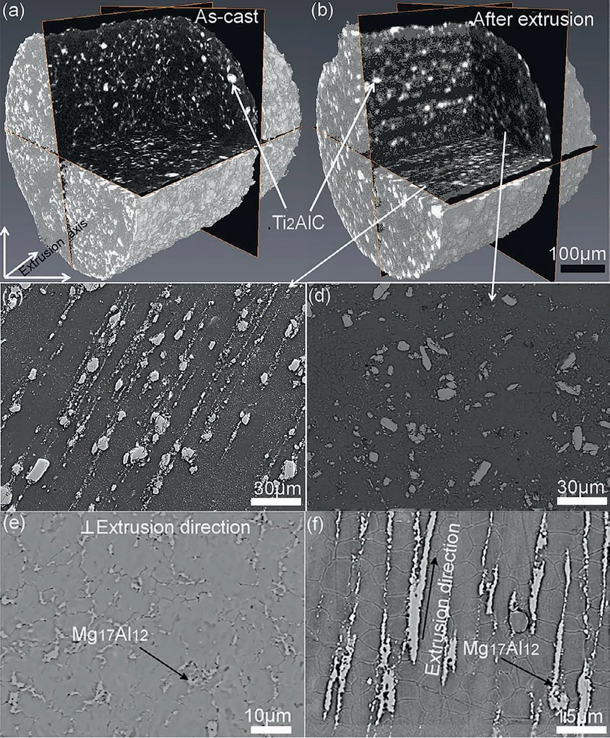
Fig.4.(a) and (b) 3D-CT reconstruction images on Ti2AlC-AZ91D composite before and after extrusion,(c) and (f)//ED axis,(d) and (e)⊥ED axis [41].
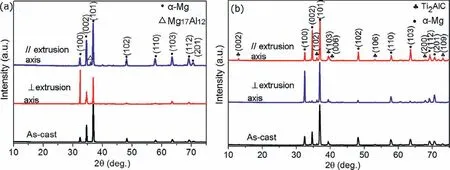
Fig.5.(a) and (b) X-ray diffraction pattern of AZ91D and 10 vol.%Ti2AlC-AZ91D composite in the as-cast and extruded states.[41].
Magnesium and MAX phases are both kinking nonlinear elastic,KNE,solids,hence the combining of two KNE solids enable composites to exhibit exceptional properties.In addition,the inherent nano-layered structure of MAX phases combines metal-like and ceramic-like properties,which endows matrix material better mechanical properties.In this part,we will report the mechanical properties of Ti2AlC reinforced AZ91D magnesium composites and summarize their fracture behavior,strengthening mechanism and deformation behavior.The unique anisotropic mechanical and physical performances of the textured composite by hot extrusion are also reviewed.Table1 compiles an overview of Ti2AlC-AZ91D and comparative composite material in the literature.
4.1.In-situ fracture behavior of as-cast Ti2AlC/Mg

Fig.6.Typical tensile curves of 5 vol.%Ti2AlC-AZ91D composite [39].
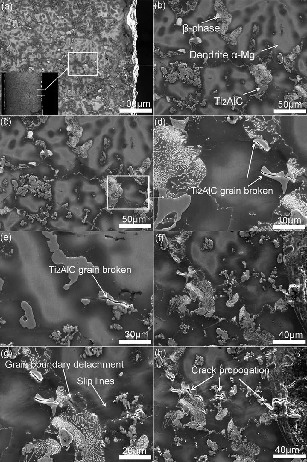
Fig.7.(a)-(h) the deformation morphologies of the 5 vol.%Ti2AlC-AZ91D composite during in-situ tensile test [39].

Fig.8.Fracture surfaces of (a) 5vol.% and (b) 10vol.%Ti2AlC reinforced AZ91D composites after tensile test [39].
In-situ tensile test was conducted to study the crack initiation and propagation on 5 vol.%Ti2AlC-AZ91D composite.Fig.7 shows the process of cracking initiation and propagation in composite,which corresponds to the location of the solid line break that occurred in Fig.6.With the increasing loads,no interfacial debonding appeared between Ti2AlC and Mg matrix while some Ti2AlC particles broke into two parts,as shown in Fig.7(c)-(e).After that,due to the mismatch in CTE,plastic deformation occurred in Mg matrices close to the interface.Slipping bands also appeared near the interface,and obvious shearing deformation occurred in Mg matrix among the broken Ti2AlC particles (as shown in Fig.7(g).Furthermore,cracks expanded along grain boundaries where the Mg17Al12exists rather than along the interfaces of Ti2AlC and Mg,and finall cracks connected among the cracked Ti2AlC particles.During the in-situ tensile test,no interfacial debonding suggests that the Ti2AlC and Mg exist strong interfacial bonding.
4.2.Tensile properties
4.2.1.Tensile fracture behavior in as-cast Ti2AlC/Mg
Fig.8 exhibits the tensile fracture morphologies of ascast composites.Ti2AlC particles delaminate obviously and are covered with a thin Mg layer in composite.As the volume fraction of Ti2AlC increases,the shorter torn edges indicate that less Mg takes part in plastic deformation.Unlike the cases of SiC and TiC [10,50,51],there is no interfacial decohesion between Ti2AlC and Mg-matrix.The result of tensile properties from Table1 shows that 10vol.%Ti2AlCAZ91D composite displays the best value (215 MPa) of ultimate tensile strength (UTS).This value exceeds the reported 10vol.% SiC-AZ91D composite prepared by stir-cast (172 MPa) and powder metallurgy (135 MPa).Furthermore,the elongations of composites significantl decrease with the increase of Ti2AlC content (from 3.4% to 0.7%).
In addition,the theoretical evaluations of elastic moduli in Ti2AlC/Mg composite were predicated by (i) mixture rule expression,(ii)the Hashin and Shtrickman equation and(iii)the Halpin-Tsai equation,the measurement results could be seen in Fig.9.To investigate the influenc of aspect on the Ti2AlC reinforcement,different aspect ratios were also employed to calculate.The result shows that the value of elastic moduli approximate to that predicted by Halpin-Tsai equation with an aspect ratio of 3.


Fig.9.Elastic modulus predicted results [39].
Giving the aspect ratio (S) of Ti2AlC as 3,the interfacial shear strength between Ti2AlC and Mg can be determined from the shear mechanism,where the extent of particle loading depends on the aspect ratio of the reinforcing particles.According to the situation of particles in the metal matrix,the S for maximal loading is [52]:

whereσTi2AlCandτistand for particle strength (about 1000 MPa) and the interface’s shear strength,respectively [53].
The value of the interface’s shear strength between Ti2AlC and Mg can be estimated to be about 330 MPa,which is higher than the UTS of as-cast 10vol.%Ti2AlC-AZ91D composite (215 MPa).This is the reason why no interface decohesion occurred between Ti2AlC and AZ91D matrix.It is also confirme that Ti2AlC and matrix have strong interfacial bonding,which is different from the interface decohesion of SiC or TiC reinforced Mg composites [10,50,51].
4.2.2.Tensile fracture behavior in hot extruded as-cast Ti2AlC/Mg
After hot extrusion,Ti2AlC particles remained clear delamination in ⊥ED axis (see Fig.10(b)),as in the case of as-cast composites.However,interface decohesion between Ti2AlC and the matrix was found in// ED axis (see Fig.10(c)).Correspondingly,textured Ti2AlC-AZ91D composites exhibit anisotropic properties and different strength characteristics.As shown in Fig.10(a),tensile stress-strain curves suggest that hot extrusion could optimize the tensile performances.Taking textured 10vol.%Ti2AlC-AZ91D as specimen,for the specimen// ED axis,the values of UTS(375 MPa) and YTS (275 MPa) increased respectively by 74% and 103% compared with as-cast Ti2AlC-AZ91D composite of 215 MPa and 135 MPa.For the specimen ⊥ED axis,UTS value can reach 285 MPa,which also exceeds the corresponding as-cast composite.
4.2.3.The reinforced mechanism in tensile strength
In general,there are different reinforced mechanisms for metal-based composites.Considering the effect of matrix grain size and particulate distribution on yield tensile strength in Ti2AlC-AZ91D composites,the individual contribution strengthening effects ofσHP(Hall-Petch strengthening effect),σCTE(mismatch of thermal coefficients) andσor(reinforced particle size effect) to the yield strength was conducted through the following equations [54,55] and the results are shown in Fig.11.

WhereσMgis the yield strength of the matrix (73 MPa).M=6.5 represents Mg’s mean orientation factor [56].A=0.2 represents the constant of dislocation forest in Mg matrix [56].G=17.3 GPa represents Mg’s shear modulus[57].b=3.21 × 10⁻¹⁰m represents Mg’s Burgers vector.Danddstand for the matrix grain size and Ti2AlC particle size,respectively.Poisson’s ratio in Mg is taken asvMg=0.35[54].frepresents the volume fraction of Ti2AlC.ΔTis the change of temperature in the process of matrix solidificatio(about 475 °C).K=280 is the constant value in AZ91D.Δαcharacterizes the coefficien of thermal expansion (CTE),the CTEs of Ti2AlC are about 7.1±0.3 × 10⁻⁶K−1at a-direction and 10.5±0.5 × 10⁻⁶K−1at c-direction,while that of magnesium is 26 × 10−6K [58].
For as-cast Ti2AlC-AZ91D composite,Hall-Petch strengthening and Forest strengthening are primary strengthening mechanisms for tensile strength,while Orowan strengthening plays a less important part.For extruded Ti2AlC-AZ91D composite,the influenc of the Hall-Petch strengthening and Orowan strengthening mechanisms is more significan compared to Forest strengthening.It is well known that Hall-Petch strengthening mechanism is the overriding influencin factor for different reinforcement type reinforcement in Mg-based composites.This effect depends more on the volume fraction of the reinforcements than on the particle grain size.Furthermore,the mismatches of CTE between Ti2AlC and Mg would cause thermal strain and high dislocation densities near matrix/reinforcement.However,it has been shown that Orowan strengthening is not considered an important factor in microparticles reinforced Mg matrix composite.Some sub-micron Ti2AlC particles (800 nm) and Mg17Al12precipitates (200 nm) were redistributed into Mg matrix after hot extrusion,where they were previously accumulated around the Mg grain boundaries.Due to the redistribution of Ti2AlC and Mg17Al12,Orowan loops would exert back stress on dislocation sources resisting the dislocation movement,resulting in the great enhancement of Orowan strengthening.
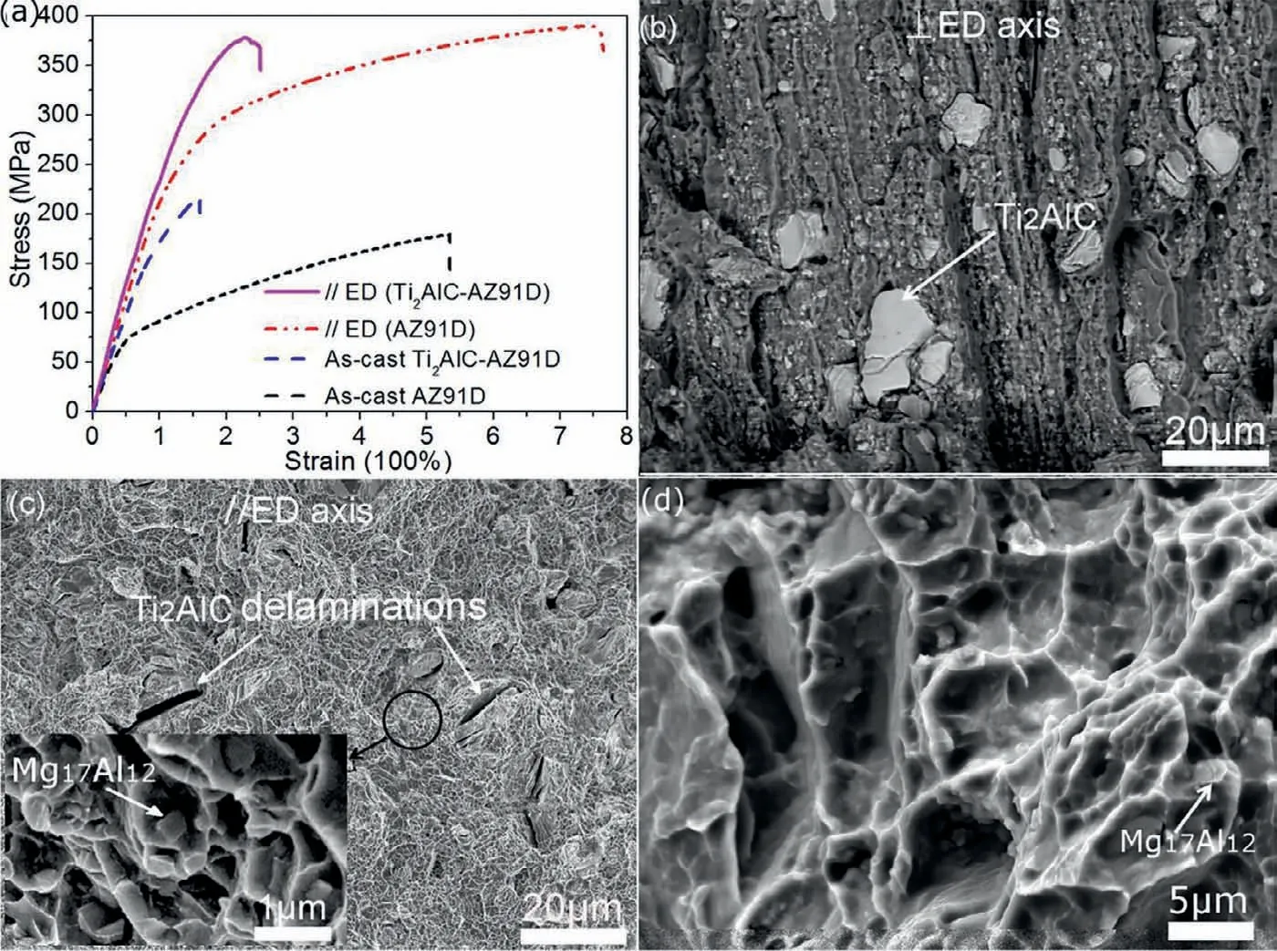
Fig.10.(a) Tensile stress-strain curves under room temperature for as-cast and extruded specimens;Different tensile fracture surfaces in extruded specimen:(b) ⊥ED axis (c)// ED axis (d) as-cast and (d) AZ91D alloy (// ED) [39,40].
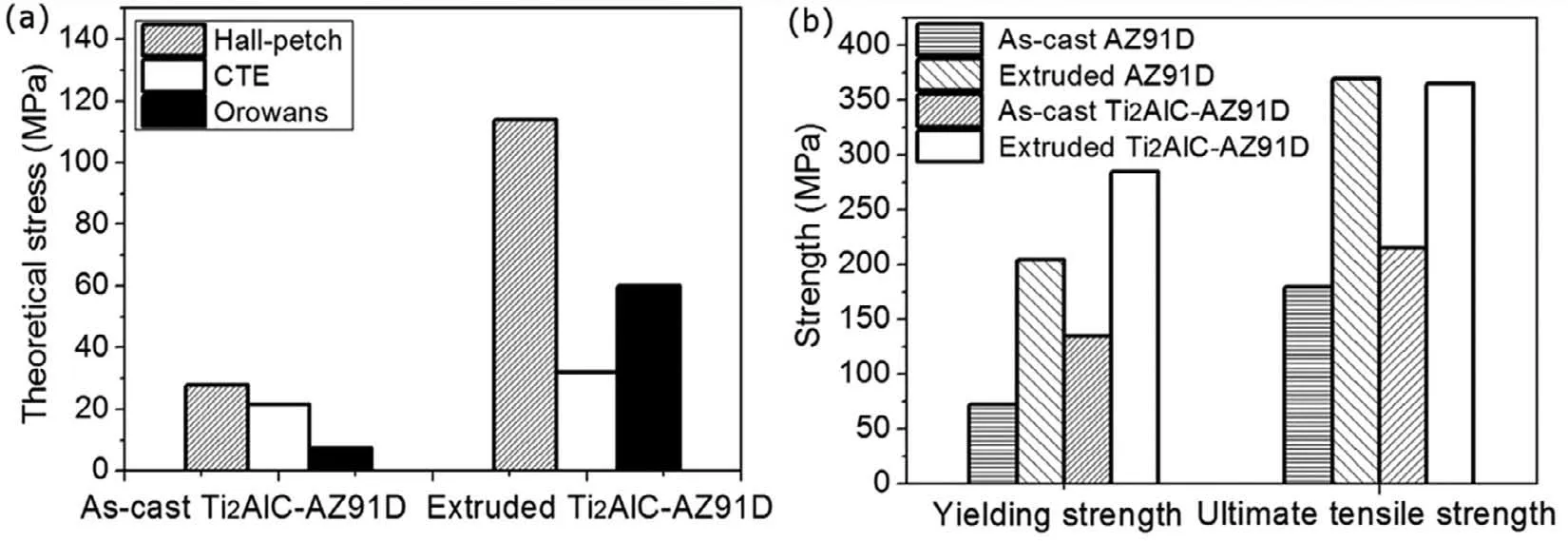
Fig.11.(a) The calculated contribution of σHP σCTE and σor to the yield strength of as-cast and extruded 10vol.%Ti2AlC-AZ91D composites;(b) distribution of yield strength and ultimate tensile strength [40].
4.3.Compressive properties
Fig.12(a) shows the compressive stress-strain curves of extruded specimens.Similar to the reported research [37],the stress-strain behavior on different compressive axis can be controlled by hot extrusion,notably for extruded Ti2AlCAZ91D composite.The values of UCS are 510 MPa (//ED)and 400 MPa (⊥ED) in extruded 10vol.%Ti2AlC-AZ91D composite,which increases respectively 28% and 12% in comparison with extruded AZ91D alloy of 396 MPa and 355 MPa.Furthermore,the fl w curves for C// ED specimens have the characteristic with concave work-hardening region.In the relevant directions,the strain hardening rate of the Ti2AlC-AZ91D composite is obviously higher than that of AZ91D,as can be seen in Fig.12(b).
The compressive fracture surfaces of as-cast and extruded composites are shown in Fig.13.Due to the“pinning effect”of Ti2AlC in AZ91D matrix,the serious torn zone occurred above the Ti2AlC in the glide direction.The typical delamination and kinking bands of Ti2AlC MAX phases are shown in the enlarged area of Fig.13(c),which suggests that Ti2AlC particles participated in the plastic deformation.This phenomenon also occurred in C// ED composite after hot extrusion (see Fig.13(f)).On the contrary,some Ti2AlC particles presented the clear surfaces in C ⊥ED composite (see Fig.13(e)).
To illustrate the deformation mechanism of oriented Ti2AlC particles in// ED and ⊥ED specimens under compressive force,the schematic version was shown in Fig.14.In ternary nano-layered MAX phases structure,the strong covalent M-X bonds are interlaced with A layers through weaker M-A bonds.Because of the layered structure and high c/a ratio,the MAX phases present anisotropy during plastic deformation in that dislocations are mostly confine to the basal planes.Thus,there are two typical deformation modes.One is interlayer sliding and the other is kinking bands[15,59-62].As shown in Fig.14(b),the force distributed along basal plane (F •cosθ) is determined by the angle between Ti2AlC basal planes (0001) and the compressive axis.For C// ED specimen,Ti2AlC basal planes are inclined with compressive stress,and interlayer sliding happened among the basal planes.In contrast,for C ⊥ED specimen,Ti2AlC basal planes are parallel with compressive stress,and the plastic deformation in Ti2AlC MAX phase is characterized mainly by the delamination between basal planes and kink-band formation.

Fig.12.The compressive stress-strain curves of extruded specimens [40].

Fig.13.Different compressive fracture surfaces (a) 5vol.%,(b-c) 10vol.%as-cast Ti2AlC-AZ91D composite;(d-f) extruded 10vol.%Ti2AlC-AZ91D[39,40].
5.Physical properties
5.1.Damping properties

Fig.14.(a) The reducible structure of Ti2AlC particles;(b) and (c) the common deformation behavior of Ti2AlC particles under compression stress[40].
Materials with high damping properties play a significan role in engineering applications that need to reduce mechanical vibrations and control noise.It has been reported that there are two basic ways to regulate the damping properties in magnesium matrix composites [25,45,63].One is applying high damping quality reinforcements and regulating their contents,the other is regulating the microstructure of matrix to arouse the energy dissipation sources.These sources are usually attributed to the crystal defects,such as the formation of high dislocation density near the reinforcement-matrix interface.For Ti2AlC particles reinforced AZ91D magnesium composite,we discussed the effect of the temperature,the frequency and content of reinforcement on its damping capacities.This section will focus on the damping mechanism of Ti2AlC-AZ91D composite combine with different effects on damping capacities.
5.1.1.Influenc of temperature on damping capacity
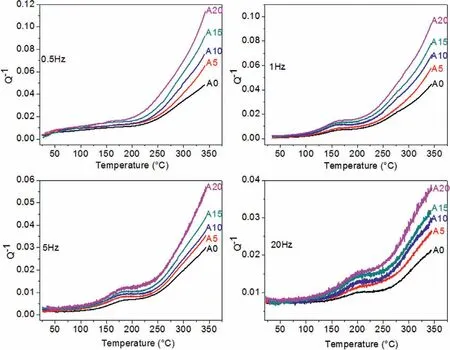
Fig.15.Damping capacity of AZ91D alloy and Ti2AlC-AZ91D composites as a function of temperature at different frequencies [45].
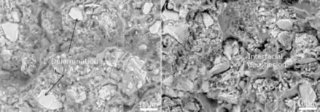
Fig.16.Tensile fracture surfaces of 10vol.%Ti2AlC-AZ91D showing (b) at RT and (c) at 200 °C [45].
The influenc of temperature on damping capacities in the AZ91D alloy and composites for several frequencies is shown in Fig.15.While damping capacities of composites poorly depend on the temperature when the temperature is below 200 °C,it significantl improves when temperature is above 200 °C.This turn in damping mechanism can be illustrated by different tensile fracture surfaces at room temperature(RT)and high temperature.As shown in Fig.16,the fracture mode in Ti2AlC changed from the delamination without interface debonding at RT into the interfacial debonding at high temperature,which suggests that at 200 °C,the interfacial bonding strength in Ti2AlC-AZ91D becomes weaker than the metallic Ti-Al bonds of Ti2AlC grains.This transformation of tensile fracture mode indicates that damping mechanism dominated by the interfacial gliding when increasing temperature replaces it caused by dislocation gliding at low temperatures.This transformation of tensile fracture mode indicates that damping mechanism dominated by dislocation gliding at RT is replaced by the new one controlled by the interface gliding at 200 °C.
In addition,the damping capacities increase as the volume fraction of Ti2AlC increases at all temperatures.As Ti2AlC particles exhibit high dislocation density,their intrinsic damping capacity makes a contribution to overall damping.It indicates that the damping mechanism at low temperature is primarily attributed to the intrinsic damping of constituents in composite.
5.1.2.Dislocation damping

Fig.17.Interface microstructure of Ti2AlC/AZ91D:(a) dislocation interactions in the Ti2AlC grain,(b) nano-sized Mg particles were formed among Ti2AlC particles,(c) a amorphous Mg layer between Ti2AlC and Mg grains[45].
From Fig.15,it can be concluded that Ti2AlC-AZ91D composites present different damping mechanism below and above 200 °C.During the solidificatio of composites,the large difference in the thermal expansion coefficien (Δα) between theTi2AlC ceramic and the AZ91D metal could bring about the formation of dislocations.The generated interfacial dislocation density can be calculated as follows [64]:

WhereBandbstand for geometrical constant and Mg burgers vector [54],respectively.fis Ti2AlC volume fraction.ΔTandtstand for the change of temperature and the minimum dimension of reinforcement,respectively.According to the Eq.(5),it can be seen that the dislocation density rises as the volume fraction of Ti2AlC rises for composites.Hence,the composites with higher content of Ti2AlC particles have a higher damping capacity.
5.1.3.Interface damping
At high temperatures (above 200 °C),interfacial damping dominates the damping mechanism.As shown in Fig.17,a great number of dislocation interactions can be observed inside the Ti2AlC grain.Energy dissipation can be carried out through these dislocations motion,thereby enhancing the damping capacity.Many nano-size Mg grains were found among the Ti2AlC particles(see Fig.17(b)),which strengthen the matrix and further enhance the composite stiffness.In addition,it has been shown that the big mismatch of lattice will cause some interface defects,such as high interfacial energy in an incoherent interface.The appearance of a thin amorphous Mg layer between Ti2AlC and AZ91D matrix(see Fig.17(c)) can not only reduce this interfacial energy but improve the interfacial bonding strength.Therefore,due to the strong interface bonding,interface damping effect does not work at room temperature.In contrast,at the elevated temperature,the interface sliding between Ti2AlC and magnesium matrix happened because of the decrease in friction energy.Under heat activation,interfacial slip occurred when the interface shear stress could overcome friction resistance.In this way,one of the major factors for generating damping is the decrease in friction energy induced by interfacial slip [65].
In addition,it is known that frequency is the reciprocal of the stress’s cycle period.Therefore,a more noticeable interface slide happens at a low frequency than at a high frequency with the same stress intensity.According to Zener’s thermoelastic theory,damping capacities increase with the increasing frequency when frequencies are lower than Zener frequency(160 Hz) [66].Differently,our results in Fig.15 presents another phenomenon that damping capacities decrease with increasing frequency in the measured range of temperature,which indicates that the thermoelastic damping mechanism does not contribute to the damping in these composites.
5.1.4.Damping peaks analysis
Fig.18(a) shows that the damping peaks shift toward higher temperatures with increasing frequencies.The activation energy (H) of damping peaks at different frequencies is calculated and given in Fig.18(b).H values of the as-cast AZ91D alloy are determined to be 116 kJ/mol,and 15vol.%Ti2AlC-AZ91D composite to be 128 kJ/mol.These two values are in the range of the grain boundary diffusion energy (82-105 kJ/mol) and the lattice self-diffusion energy (135 kJ/mol)of Mg.The grain boundary diffusion and lattice self-diffusion are important factors to control boundary slip,especially for grain boundary slip and interface slip.Hence,it is assumed that the boundary slip causes the damping peaks.In addition,due to the interface decohesion in graphite-AZ91D and SiCAZ91D composites,the H values for these two composites have been reported to be 123 kJ/mol and 110 kJ/mol,respectively,which are lower than that of Ti2AlC-AZ91D composite.
5.2.Thermal conductivities and electrical properties
The physical performances of textured 10vol.%Ti2AlCAZ91D composites and AZ91D alloy are listed in Table 1.According to Table 1,the bigger difference in thermal conductivity occurred in extruded 10vol.% Ti2AlC-AZ91D composite,in which thermal conductivity//ED axis (70.08 W(m•K)−1) exceeds that of ⊥ED axis (5.03 W(m•K)−1).However,this phenomenon was not found in extruded AZ91D alloy (72.21 W(m•K)−1and 73.05 W(m•K)−1,respectively).This difference could be explained by Fig.4.The cross-section area fraction of Ti2AlC particles//ED axis exceeds that of ⊥ED axis due to the reorientation of Ti2AlC after hot extrusion,which means that more thermal flu is limited in ⊥ED axis instead of// ED axis for the composite.On the contrary,the thermal conductivity in ⊥ED axis exceeds that in// ED axis for extruded AZ91D alloy.After hot extrusion,most of the basal planes are parallel to ED axis.Because the atoms in basal planes are the most close-packed,phonons or defects are more likely to scatter the electron in this direction.This indicates that the free path of electrons is seriously limited by the//ED axis and causes lower thermal conductivity [67,68].

Fig.18.(a) Comparison of the damping peaks in as-cast AZ91D alloy and composites,(b) the logarithmic plots of angular frequency vs reciprocal peak temperature for A0 and A15 samples;A15 represents 15vol.% Ti2AlC-AZ91D composite,and so on [45].

Fig.19.Comparison of the temperature-dependent resistivity in extruded AZ91D alloy and composite,B10 represents 10vol.%Ti2AlC-AZ91D composite.[45].
Similar to the thermal conductivity,the anisotropy also occurred in electrical resistivity,more electrical flu are limited in⊥ED axis,rather than in//ED axis.Furthermore,Fig.19 shows curves of resistivity (ρ(T)) vs.temperature plotted for AZ91D alloy and reinforced composites.According to Mathiessen’s rule,the ideal resistivity (ρi) can be described as follows:

whereρ(T) andρi(T)stand for the total resistivity and the ideal resistivity,respectively.ρ0represents the residual resistivity (RR) which results from electron-scattering by imperfections.Extruded composite has a greater residual resistivity(RR) than extruded AZ91D alloy,which is attributed to the distortion of AZ91D matrix and destruction of lattice periodicity resulting from the appearance of nano Ti2AlC and Mg17Al12in the extruded composite.Grain boundary and lattice distortion are the scattering sources that hinder the free movement of electrons.As a result,the residual resistivity increases and the mean free path of electrons have been restricted [69,70].
In addition,the slope of theρ(T) curve shown in Fig.19 represents the intrinsic transport properties.Contrary to the higher slope in extruded AZ91D alloy// ED axis,the slope of extruded composite in// ED is lower than that of in⊥ED.This difference is attributed to the same magnitude of electrical resistivity between Ti2AlC and AZ91D and the anisotropic transport property of Ti2AlC.For example,the dρ/dT value of Ti2AlC in basal plane and perpendicular to it is 0.1 μΩ·cm·K−1and 1.75 μΩ·cm·K−1,respectively [71].Furthermore,compared to the extruded AZ91D alloy,the variations in dr/dT and ratio RRR between//ED and⊥ED specimens demonstrate that the introduction of Ti2AlC particles makes contribution to the scattering of the conductivity electrons in AZ91D alloy.
6.Tribological property
MAX phases display superior tribology properties and have been widely used in MMCs to improve their wear resistance.Like the microstructure of graphite,nano-layered MAX ceramics have self-lubricating property and exhibit ultra-low friction coefficient along the basal planes [25,33,72].With configuratio of high c/a ratio,MAX phases also present the anisotropy of tribological properties.Using pin-on-disk tester,the dry sliding wear behavior of Ti2AlC-AZ91D composites was studied against a Cr15 steel disc,at the sliding speed of 0.5 m/s and the loads from 10 N to 80 N.
6.1.Wear rate
The volumetric wear rate at sliding velocity of 0.5 m/s for the different specimens is shown in Fig.20.For all specimens,the volumetric loss increased as the loads rose.Obviously,the introduction of Ti2AlC reinforcement to magnesium matrix brings the enhancement in the wear resistance at all applied stress.

Fig.20.Volume loss in as-cast AZ91D alloy and composites [73].
The Archard’s equation was generally used to evaluate the wear mechanism of material:

where V and L stand for the wear volume and sliding distance,respectively.V/L represents the wear rate.W and H stand for the applied load and the sample hardness,respectively.K andkrepresent the Archard’s constant and the specifi wear rate,respectively.Fig.21 depicts the specifi wear ratekin several samples.According to Eq.(7),the increase of hardness enhances the capacity to resist plastic deformation and decrease wear rate in materials [74].Therefore,the wear resistance of all composites outperforms AZ91D alloy,especially with the addition of more Ti2AlC.However,references have pointed out that the introduction of SiCpreduces the wear resistance of SiCpreinforced magnesium composite at speed of 0.5 m/s and load of 30-80 N,thereby reducing the wear rates of composite [75,76].On the contrary,Ti2AlCAZ91D composites exhibit the lower specifi wear rate in comparison with pure as-cast AZ91D in our work.

Fig.21.Specifi wear rate in tested samples [73].
6.2.Worn surface and debris
Generally,worn surfaces and wear debris can give us some clue about the wear mechanism.Under almost all tested conditions,a common feature with fin grooves parallel to the sliding direction emerged,as depicted in Fig.22.These grooves are formed by the counterbody’s hard surface ploughing the magnesium pin’s soft surface.For low hardness AZ91D alloy,the wear mechanism is primarily caused by the removal of the surface.As shown in Fig.22(d),SiCp-AZ91D composite exhibits extensive abrasion due to the detached and fractured SiCptrapped at the sliding interface [76].In contrast,less abrasion and grooves appeared in Ti2AlC-AZ91D composite (see Fig.22(b) and (c)).This is due to great interfacial bonding between Ti2AlC and Mg,which avoids detachment during sliding.

Fig.22.SEM results of different composites with the load of 40 N:(a) as-cast AZ91D,(b) and (c) 5vol.% and 10vol.%Ti2AlC-AZ91D composite,(d)10vol.%SiC-AZ91D composite [73].

Fig.23.EDS map in the wear debris collected for 10vol.%Ti2AlC-AZ91D composite with the load of 80 N [73].
The EDS maps for the wear debris of composite and worn surfaces of AZ91D pin were respectively shown in Figs.23 and 24.The oxidative wear surface was distinguished by the generation of spots that covered nearly the whole surface of the magnesium pin.As shown in Fig.23,the presence of strongly oxidized wear debris demonstrates the formation of an oxidation layer.Meanwhile,the oxygen distribution in Fig.24 suggests that the oxygen content is higher in the region where Ti2AlC particles exist.In addition,Fig.17 have shown that nano-size Mg grains formed around Ti2AlC particles.During wear test,nano-Mg grains oxidized easily and then oxidation layer is gradually formed.It has been reported that this oxide layer avoids the contact between the pin and the conterbody,resulting in a lower friction coefficien[76-78].
6.3.Effect of Ti2AlC orientation
Textured Ti2AlC/Mg composites exhibit anisotropic mechanisms in tribological property.Fig.25 presents the distinctive worn surfaces of extruded 10vol.%Ti2AlC-AZ91D composite at sliding//ED and ⊥ED axis,respectively.As can be seen in Fig.25(a),in the case of sliding direction parallel to extrusion axis,there were no scratches or grooves on the surface.The expanded region in Fig.25(b) shows that some Ti2AlC particles delaminated into layers,indicating that Ti2AlC has self-lubricant quality.On the contrary,in the case of sliding direction perpendicular to extrusion axis,more grooves with furrows occurred and Ti2AlC particles were broken.According to the previous discussion,as the interfacial bonding strength of Ti2AlC/Mg is higher than interfacial shear strength along the Ti2AlC basal planes,the slide could happen along the Ti2AlC basal planes under the shear force.However,when Ti2AlC particles were broken,the lower interfacial bonding strength is insufficien to support the sliding shear strength,and then the particles were pulled out,which leads to the abrasive wear mechanism (see Fig.25(c).)
7.Potential applications of magnesium matrix composite reinforced by Ti2AlC particles
Due to their lightweight,good dimensional stability and mechanical integrity,magnesium-based composites have become intriguing candidates for replacing traditional magnesium alloys and composites in aerospace,automotive,military and electronics industrial branches [79].In the automotive industry,if vehicle weight could reduce by 10%,fuel economy will increase by 7% [80].As shown in Fig.26,engine block and belt pulley transmission parts have been widely used in motorcycles and automobiles.Generally,the engine cylinder block of motorcycle is made of aluminum cylinder and iron cylinder liner.This structure has low efficien y of heat transfer because of the heterogeneous metal interface.

Fig.24.EDS map in the counterpart surface with the load of 80 N [73].
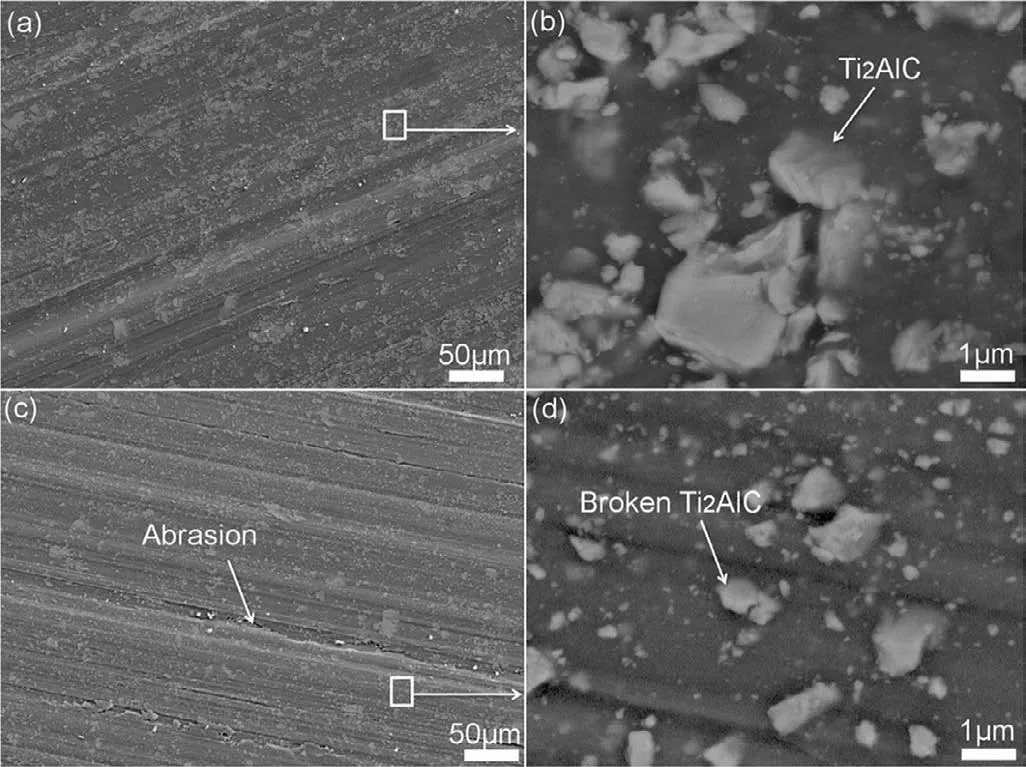
Fig.25.SEM results of textured 10vol.%Ti2AlC-AZ91D composite with the load of 80 N:(a-b) sliding direction//ED axis and (c-d)⊥ED axis,respectively [73].
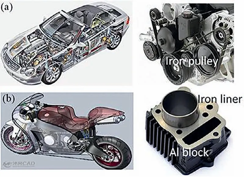
Fig.26.(a) The iron pulleys of cars and (b) engine block equipped with iron liner of motorcycles
The density of iron is 7.9 g/cm3,much higher than Ti2AlC/Mg composite (1.9 g/cm3).To solve these problems and obtain a new cylinder,as shown in Fig.27,we designed and developed an integrated forming process,including powder metallurgy,semi-solid casting,hot extrusion and high pressure die casting.The Ti2AlC/Mg billet was fabricated by semi-solid stirring casting method with the introduction of Ti2AlC particles into AZ91D alloy.Then,cylinder liner was obtained by hot extrusion of semi-solid billet.Finally,the line was moved into the mold and was encapsulated by AZ91D alloy during high pressure die casting.As shown in Fig.28,the weight of original LPw200 motorcycle reduced from 1.7 kg to 1.25 kg with a weight reduction of 26% with method.This innovation can achieve the goal of energy conservation and emission reduction in the transportation sector in the future.
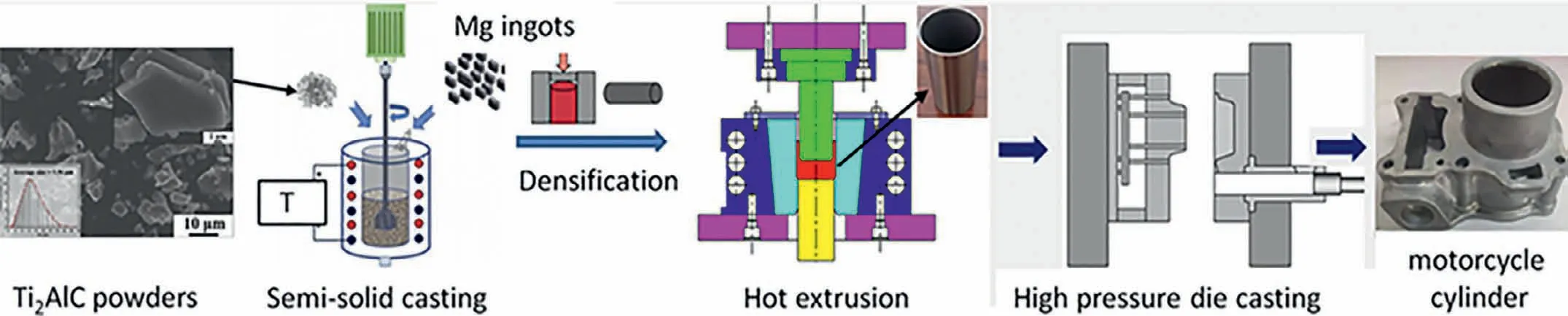
Fig.27.The integrated forming process of Ti2AlC reinforced magnesium matrix composite motorcycle cylinder.

Fig.28.Production and application of LP200 motorcycle cylinder block with magnesium matrix composite cylinder liner,and the weight compared with traditional cylinder.
8.Summary
Ti2AlC and Ti3SiC2are representatives of novel ternary MAX phases,especially for Ti2AlC,its unique properties combined with low density and high specifi strength of magnesium can promote the lightweight development of aerospace,transportation,automotive and electronics industry fields making Ti2AlC-Mg composites a promising material with a broader application prospect.This review focuses on fabrication process,microstructures,mechanical properties,the potential application of AZ91D magnesium matrix composite reinforced by MAX phase.The A-site atoms in MAX phases can affect the interfacial structure and create the idea of controlling interfacial structure by regulating A-site elements and its solid solution ratio in MAX phase,such as Ti3(Si1-xAlx)C2.According to the in-situ observations,cracks initiated in Ti2AlC particles rather than the interface.
Due to the high aspect ratios of MAX phases,hot extrusion can regulate Ti2AlC orientation in AZ91D matrix and hence anisotropic properties.After tensile test,clear delamination of extruded Ti2AlC particles occurred in ⊥ED axis,while interface decohesion between Ti2AlC and the matrix was found in// ED axis.// ED axis,the values of UTS (375 MPa) and YTS (275 MPa) increased respectively by 74% and 103% in comparison with the as-cast Ti2AlC-AZ91D composite of 215 MPa and 135 MPa.As more thermal flu is limited in ⊥ED rather than// ED axis,the lower thermal conductivities was found in ⊥ED composite.Electrical resistivity also revealed this similar anisotropic result.
Ti2AlC makes great contribution to the damping capacity in composites.The interfacial damping capacity plays the dominant part in composites,as the temperature increases,especially over 200 °C.In contrast to the extensive abrasions generated by SiCpdetachment in SiCp-AZ91D composite,less abrasion and grooves were observed in Ti2AlC-Mg composite due to the strong Ti2AlC-Mg interfacial bonding.
As MAX phase reinforced Mg composites provide suffi cient deformation capacity,with great self-lubricated capacity,high wear resistance and high damping capacity,it can be used in the automotive industry,such as motorcycle cylinder block.In addition,the integrated forming process is an important trend in the development of new type of magnesium matrix composites for engineering production.
Acknowledgment
This work was supported by the National Natural Science Foundation of China (No.52175284,52130509 and 52075543),the State Key Lab of Advanced Metmals and Materials (2021-ZD08).Thanks to the technical support of BL13W1 Beamline in Shanghai Synchrotron Radiation Facility (SSRF) and Gaomi Xiangyu company.
 Journal of Magnesium and Alloys2022年6期
- Journal of Magnesium and Alloys的其它文章
- EDITORIAL BOARD
- Aims and Scope
- Surface oxidation study of molten Mg-Al alloys by oxide/metal/oxide sandwich method
- Production and characterisation of new bioresorbable radiopaque Mg-Zn-Y alloy to improve X-ray visibility of polymeric scaffolds
- Quantitative study on the tension-compression yield asymmetry of a Mg-3Al-1Zn alloy with bimodal texture components
- Microstructure analyses and phase-fiel simulation of partially divorced eutectic solidificatio in hypoeutectic Mg-Al Alloys