Modeling of irradiation-induced damage and failure behaviors of fuel foil/cladding interface in UMo/Zr monolithic fuel plates
Xiang-Zhe Kong · Xiao-Bin Jian · Feng Yan · Chang-Bing Tang ·Zi-Xuan Guo · Shu-Rong Ding· Yuan-Ming Li · Chun-Yu Yin
Abstract Models to describe the damage and fracture behaviors of the interface between the fuel foil and cladding in UMo/Zr monolithic fuel plates were established and numerically implemented.The effects of the interfacial cohesive strength and cohesive energy on the irradiationinduced thermal–mechanical behaviors of fuel plates were investigated.The results indicated that for heterogeneously irradiated fuel plates: (1) interfacial damage and failure were predicted to be initiated near the fuel foil corner with higher fission densities,accompanied by the formation of a large gap after interface failure, which was consistent with some experimental observations;high tensile stresses in the fuel foil occurred near the edges of the failed interface,attributed to through-thickness cracking of the fuel foil, as found in some post-irradiation examinations; (2) the cohesive strength and cohesive energy of the interface both influenced the in-pile evolution behaviors of fuel plates; a lower cohesive strength or cohesive energy resulted in faster interfacial damage; (3) after interface fracture, the thickness of the whole plate increased to a greater degree(by ~20%) than that of the samples without interfacial damage, which was attributed to the locally enhanced Mises stresses and the nearby creep deformations around the cracked interface. This study provided a theoretical basis for assessing failure in fuel elements.
Keywords UMo/Zr · Irradiation-induced thermomechanical behavior · Numerical simulation · Cohesive model · Interfacial failure
1 Introduction
UMo/Zr monolithic fuel plates are composed of a UMo alloy fuel foil and zircaloy cladding, and are regarded as promising candidates for advanced high-flux research and test reactors [1, 2]. Compared to UMo/Al dispersion fuel plates, UMo/Zr monolithic fuel plates have a higher uranium density and undergo smaller thickness increments as less swelling is induced by the chemical reactions between the fuels and the other materials. The in-pile thermal–mechanical behavior and service safety of fuel plates are pressing research topics[1,3–5],as they are closely related to the parameters employed in the fabrication process.UMo/Zr monolithic fuel plates can be fabricated by corolling [6, 7], which differs from the process used to manufacture UMo/Al fuel plates. The strength of the bond between the fuel foil and the cladding may be distributed non-uniformly [7], where weak local bonding can initiate interface failure during in-pile irradiation.It is necessary to investigate the effects of the interfacial properties on the evolution of the in-pile thermal–mechanical behavior in these fuel plates.
Interfacial or near-interface failure in UMo/Al monolithic fuel plates[3,8,10]was observed in post-irradiation examinations, as shown in Fig. 1. After irradiation, large blisters were found near the corners and edges of the fuel foil in some of the tested fuel plates [9]. Some of these failures were induced by the chemical reactions of the UMo fuel foil with the Al alloy cladding,which weakened the effective interfacial properties. Interface reactions in UMo/Zr fuel plates can be avoided to a large extent.Nevertheless, for this type of sandwich-structured fuel plate, further research on the interfacial behavior is required. The interfacial thermal–mechanical behavior of the UMo/Zr monolithic fuel plate can be described using cohesive models [11]. Cohesive models have been widely applied in simulations of cracking processes [12, 13] and have been used for predicting and analyzing fuel fractures[14].
Under demanding irradiation environments, zircaloy claddings undergo irradiation hardening, irradiation embrittlement, irradiation creep, and irradiation growth[15–17].With the increase in burn-up,irradiation creep and swelling deformations occur in the UMo fuel foil [18–21],which will influence the distribution and evolution of the stress and strain fields in the UMo/Zr monolithic fuel plate.These irradiation effects affect the interfacial mechanical interactions, causing complex non-uniform thickness increments under non-homogeneous irradiation conditions[19]. Non-uniform thermal expansions also contribute to the complexity of irradiation-related mechanical phenomena. If the foil/cladding interface fails, the heat transfer ability of the fuel plates is degraded, triggering adverse consequences. To date, modeling the interfacial behaviors in monolithic fuel plates remains limited[22]and needs to be promoted.
In this study, models were provided to describe the thermal–mechanical properties of the interface in UMo/Zr monolithic fuel plates, and the corresponding procedures were documented and applied in simulating the in-pile thermal–mechanical behaviors in fuel plates.The influence of the interfacial performance was investigated.
2 Models to describe the interfacial thermal–mechanical properties of fuel plates
2.1 Cohesive models and algorithms for describing interfacial mechanical behavior
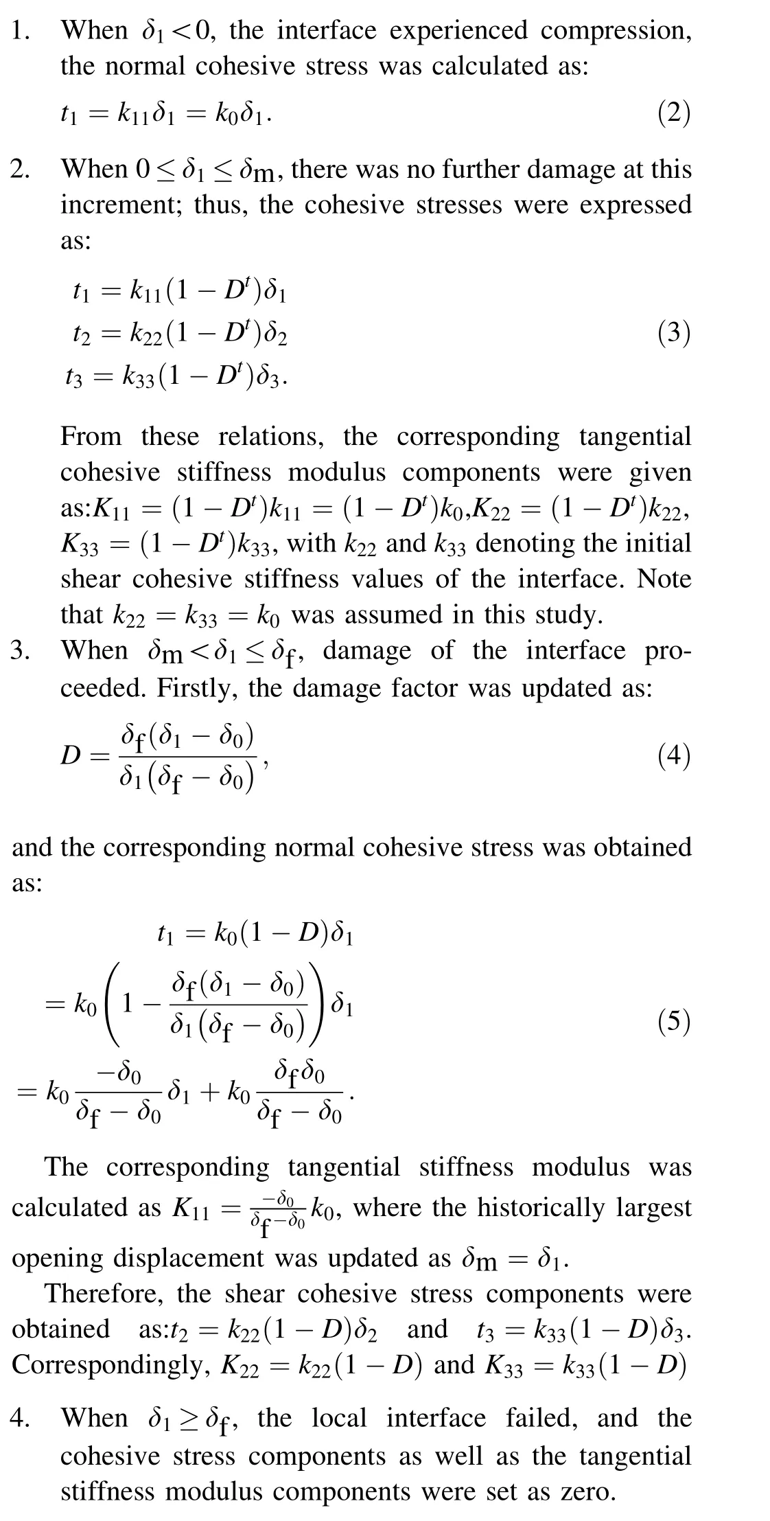
A cohesive model was used to describe the interfacial mechanical interaction between the cladding and fuel foil.The interlayer was regarded as a material layer with zero thickness,which was connected to the cladding by one side and to the fuel foil by the other. The main surface and the secondary surface were defined firstly in the contact algorithms, with the main surface having a larger stiffness or larger area. Therefore, the inner-surface of the zircaloy cladding was set as the main surface, while the outer-surface of the UMo fuel foil was the secondary surface. In fact, the cohesive model describes the relations of the interfacial tractions between the main/secondary surfaces(ti, which represents different cohesive stress components at the interface) with their opening displacement components δj.In the finite element(FE)simulation,the cohesive stresses(where one normal component and two rectangular shear components are included)of each node are solved by the local opening displacements, which refers to the separation, corresponding to the differences in the node displacement components of the secondary surface relative to those of the main surface. In the nonlinear iterative calculations, the tangential cohesive stiffness modulus should

Fig.1 (Color online)Interfacial failure of UMo/Al monolithic fuel plates from a RERTR-6[3]and b RERTR-12 [8];c blistering in the plate from RERTR-12 [9]. The sizes of the plates before irradiation are about 3.995 cm × 1.00 cm ×0.055 cm

Because of the existing nonlinearities, the process for simulating the irradiation-induced thermal–mechanical behaviors in a monolithic fuel plate was divided into a number of analysis steps, and each analysis step contained several increments.An algorithm for updating the cohesive stresses with known opening displacements must be developed.For a typical time increment,the largest historic opening displacement δm and damage factor Dtat the beginning of this increment are given, as well as the opening displacement components at the end of the increment. Note that at the first time increment of the first analysis step, the damage factor Dtwas set as 0 with δm =δ0.

Fig. 2 Bilinear model of interfacial traction and separation
The algorithm for updating the cohesive stresses at the end of the time increment was developed as follows:
2.2 Model of degraded interfacial heat transfer ability

3 Irradiation-induced thermal–mechanical behaviors of monolithic fuel plates with different interfacial mechanical properties
3.1 Finite element model
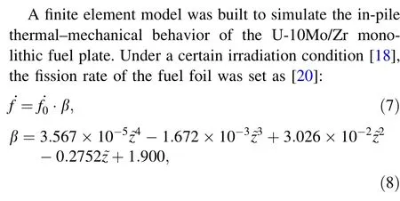

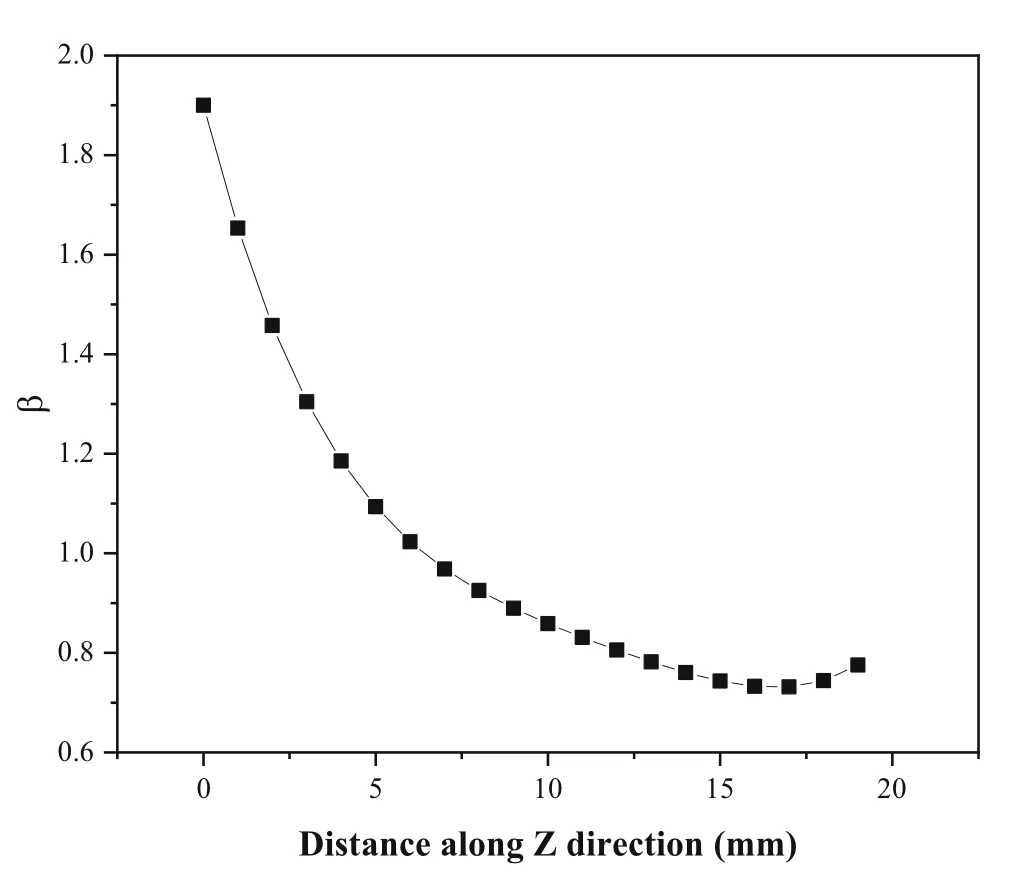
Fig. 3 Distribution of β as a function of the distance away from the heavily irradiated fuel foil edge

Fig. 4 a FE model and b boundary conditions

Table 1 Mesh parameters

Fig. 5 (Color online) Finite element meshes

In this study, uniform interfacial mechanical properties were assumed. The cohesive strength and cohesive energy were both affected by the fabrication process parameters and irradiation damage. Therefore, different parameters were selected to evaluate different effects, as listed in Table 2.Note that the initial cohesive stiffness values were all set as 105MPa/mm.
It should be mentioned that the temperature field was predicted to be slightly affected by the interface damage,using the adopted heat transfer model in Eq. (6). In the following, the results for the mechanical fields were analyzed.
3.2 Simulation results for displacement field
Cases 1,2,and 3 had the same cohesive strength,where the cohesive energy gradually declined. The distributions of the interfacial damage factors are shown in Fig. 6.
Interfacial damage was observed in Case 1, but no interfacial area failed completely. In Cases 2 and 3, interfacial failure was observed near the corner of the fuel foil.Compared to Case 2,Case 3 had a smaller cohesive energy,and thus,a larger failure area was observed in the latter.As shown in Fig. 6d, because the three cases had the same cohesive strength and cohesive stiffness,the time at which interfacial damage began was nearly the same. The interfacial damage evolved faster with an increase in the cohesive energy. In Case 1, no cracking was observed during irradiation for 120 days. In Case 2, the interface started to fail on the 60th day,whereas failure occurred on the 48th day for Case 3.

Table 2 Simulation models
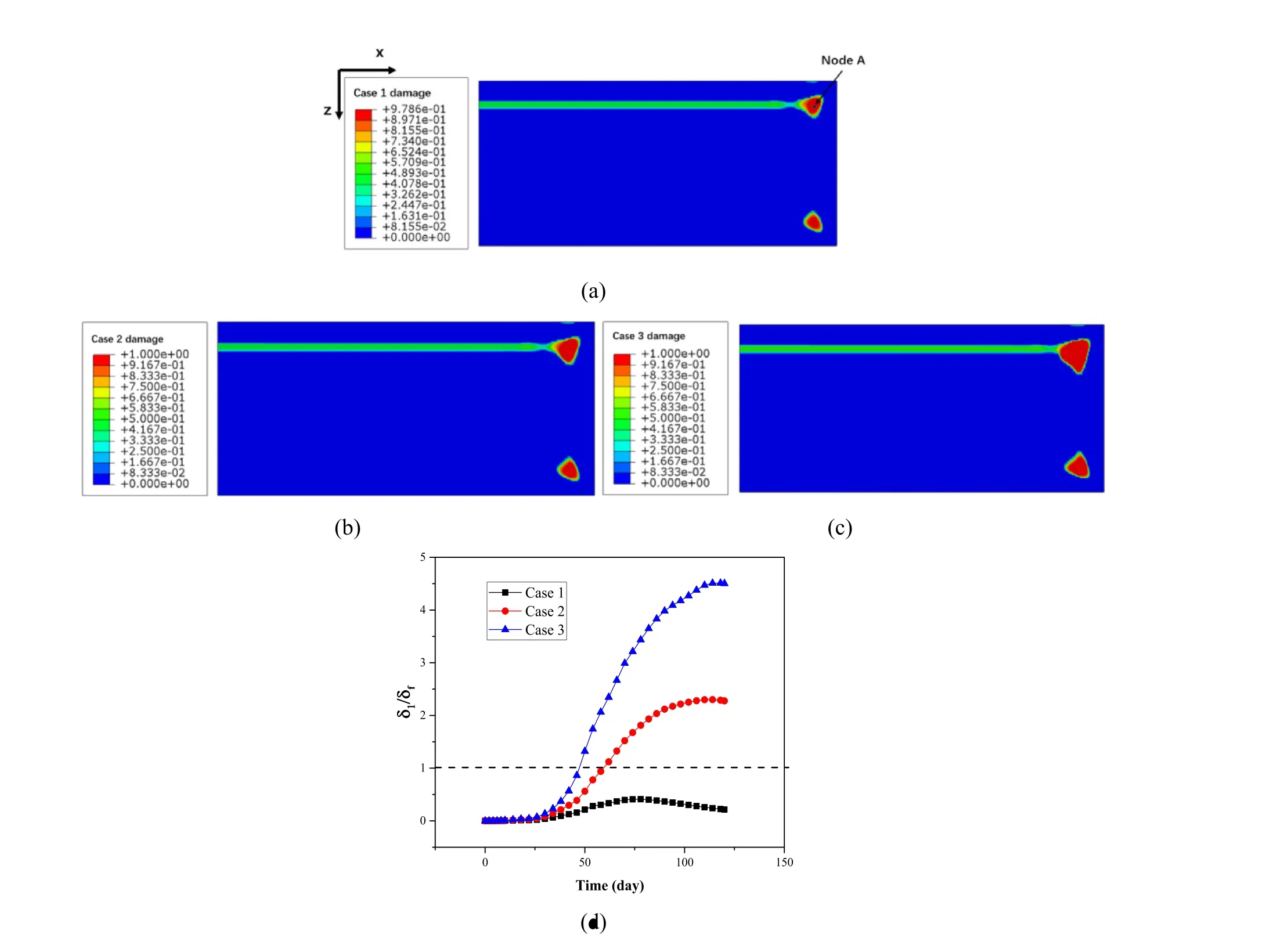
Fig.6 (Color online)Contour plots of interfacial damage factor for a Case 1,b Case 2,and c Case 3 after 120-day irradiation and(d)evolution of δ1/δf for Node A
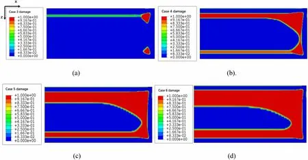
Fig. 7 (Color online) Contour plots of interfacial damage factor for a Case 3, b Case 4, c Case 5, and d Case 6 after 120-day irradiation

Fig. 8 (Color online) Contour plot of interfacial damage factor for Case 6 after a 4-day, b 10-day, c 30-day, and d 120-day irradiation
In Cases 3–6, the same cohesive energy and different cohesive strengths were assumed. The distribution of the interfacial damage factors is shown in Fig. 7. With a decrease in the cohesive strength,the cracked areas clearly expanded significantly. After 120-day irradiation, the cracked region was located near the corner of the fuel foil in Case 3, and a band-type damaged area was observed near the heavily irradiated side. In Case 4, the cohesive strength decreased to 20 MPa, and the fracture area was wider than that in Case 3. Cracking of a band-type area occurred near the heavily irradiated side, whereas a bandtype damage region appeared on the opposite side.In Cases 5 and 6, the expanded fracture areas were connected, and more serious cracking was observed in Case 6.
As shown in Fig. 8, on the 4th day, the interfacial damage in Case 6 occurred near the side subjected to stronger irradiation, and a more seriously damaged area appeared near the corner. With prolonged irradiation time,the damaged area became larger, and through-width damage was found on the 30thday, where the damage at the opposite side was greater. After the 120thday, the connected fracture areas were predicted to continue growing towards the center of the interface. The failed area may form blisters,with the development of a large gap between the fuel foil and the cladding, as shown in Fig. 1c.
Figure 9 showed the evolution of δ1/δf for Node A.With the same cohesive energy, the cases with lower cohesive strengths had higher values of δf. The time at which cracked areas appeared in Case 3 and Case 6 were nearly the same on the 56thday, whereas for Case 4 and Case 5, cracking appeared on the 52ndday. The time at which failure was initiated was similar for the four cases,but the separation rates were significantly different.

Fig. 9 (Color online) Evolution of δ1/δf for Node A
Figure 10b–d showed the through-thickness displacements of the fuel foil surface along Path 1 in Fig. 10a.When the interfacial damage was considered, the obtained thickness increments of the fuel foil in the cracked areas were smaller than those obtained without considering the interfacial damage. However, the fuel foil was thicker at the edges of the cracked areas.The data in Fig. 10d suggest that the thickness of the fuel foil continually increased even after the interface cracked. The cohesive strength had a significant effect on the thickness increments of the fuel plate.As shown in Fig. 11,the cohesive strength decreased from Cases 3 to 6, and the plate thickness increased. The maximum relative increment of the plate thickness in the no-damage case was 16.97%,whereas in Case 6,the value was 20.40%,which was 20.21%higher than the former.In particular, the thickness increments in adjacent regions differed significantly. Thickening of the fuel plate may affect the safety of the reactor core.
As shown in Fig. 12, after 120-day irradiation, obvious gaps appeared across the cracked interface of the fuel foil and cladding. This implies that similar phenomena will occur if the fuel foil fails near the interface. These predictions matched those of some post-irradiation examinations, as shown in Fig. 1. In Case 6, the gap near the side with enhanced irradiation was connected to the gap on the other side. The maximum width of the gap in Case 6 is greater than 0.08 mm. Considering that the original thickness of the fuel foil was 0.25 mm, this gap was quite considerable. If fracture of the fuel foil occurs, fission gas may be released into the gap,thereby causing more serious stresses and deformations, which will lead to obvious blistering, as found in some fuel plates (Fig. 1c).
3.3 Simulation data for strain and stress fields
As shown in Fig. 13a, the irradiation swelling strains in the fuel foil were smaller in the cracked area than in the nodamage case. The hydrostatic pressure in the cracked area was approximately 3–6 MPa. In the no-damage case, the corresponding pressures were negative, which means that the fuel foil experienced tensile stresses, leading to local enhancement of the fission-gas-induced swelling. At the edge of the cracked area, the irradiation swelling strains were obviously larger than those in the no-damage case because of the reduction in the hydrostatic pressure in the cases where the interfacial damage was considered.
Figure 13c and d showed the distributions of the equivalent irradiation creep strain and von Mises stress in the fuel foil.In the cracked areas of Case 6,the von Mises stresses were smaller than those of the no-damage case;therefore, the equivalent creep strain was also smaller. In Cases 3–5, the equivalent irradiation creep strains in the undamaged area were similar to those in the no-damage case.

Fig. 10 (Color online) a Contour plot of through-thickness displacement in fuel foil after 120 days of irradiation for Case 6; b throughthickness displacements in fuel foil along Path 1 for different cases;c locally zoomed results for red dash-box in (b); d comparison of through-thickness displacements in fuel foil along Path 1 for Case 6 and the no-damage case

Fig. 11 (Color online)a Distribution of throughthickness displacement in fuel plate for Case 6 after 120-day irradiation; b relative thickness increment of the fuel plate on Path 2 in different cases after 120-day irradiation

Fig. 12 (Color online) Cross section (about 38 mm away from the center cross section)of Case 3 and Case 6 after 120-day irradiation(a scale factor of 4 is applied to the thickness dimension)
As shown in Fig. 14, the distributions of the first principal stress in the fuel foil differed significantly for the cases with different cohesive strengths. The maximum value of the first principal stress in each case decreased when the cohesive strength was lower. When the cohesive strength was higher,as shown in Case 3, the first principal stress was maximal around the failed area. In Cases 4–6,this location was on the other side of the failed area.During irradiation,cracking of the fuel foil may occur at a location with a high first principal stress. The simulation results indicated that there were higher first principal stresses, as shown in Fig. 15, which may cause cracking through the thickness of the fuel foil. Based on post-irradiation examination using RERTR-12[8],it was found that cracking of the fuel foil occurred just around the failed part of the interface or near the interface, together with cracks along the thickness direction, as shown in Fig. 1b. The results shown in Fig. 15 can be used to interpret this phenomenon.
The thickness of the fuel plate increased as the interfacial cohesive strength became weaker.In the cracked cases,the cladding suffered larger von Mises stresses than that in the no-damage case. From Fig. 16b, the stress at the node corresponding to the dotted line in Fig. 15a was quantified as 59.15 MPa in the no-damage case, and 270.98 MPa in Case 6. Figure 16c shows the evolution of the von Mises stress. The von Mises stresses near the side with lower fission rates grew faster,with a maximum value on the 70th day. The von Mises stresses near the side with higher fission rates increased more rapidly at the beginning,reached the maximum on the 50th day, and then decreased slowly.The von Mises stresses in the cracked areas also increased rapidly. With a decrease in the cohesive strength, the equivalent plastic strains around the edge of the cracked area increased, while the equivalent irradiation creep strains decreased. Simultaneously, the equivalent creep strains increased with a decrease in the cohesive strength in the other cracked areas. Note that the equivalent creep strain was much higher than the equivalent plastic strains.It can be presumed that the thickening of the fuel plate in the cracked cases is mainly related to the larger creep deformations of the cladding.

Fig.13 (Color online)a Irradiation swelling strain;b hydrostatic pressure;c equivalent irradiation creep strain,and d Mises stress along Path 1 in fuel foil after 120-day irradiation (the dashes and arrows show the cracked areas in each case)
4 Conclusion
Models and algorithms were developed to describe the interfacial damage and fracture behaviors of UMo/Zr monolithic fuel plates, which were numerically implemented.The influences of interfacial cohesive strength and cohesive energy on the thermo-mechanical behaviors of monolithic fuel plates were determined. The main conclusions were drawn as follows:
1. Interfacial damage and failure were predicted to occur first near the fuel foil corner with higher fission densities, which was consistent with some experimental observations; a large gap appeared after the interface fracture.
2. The cohesive strength and cohesive energy of the interface influenced the in-pile behavior evolution of fuel plates;the onset of interfacial failure was delayed for cases with higher cohesive energies, and the onset of interfacial damage was earlier for cases with lower cohesive strengths.
3. Compared to the no-damage case, the thickness increments of the fuel foil were reduced across the failed area,while the overall thickness of the fuel plate increased. The decreases in both the cohesive energy and cohesive strength will lead to a greater increase in the plate thickness, where the effect of the cohesive strength dominates. In the case where the cohesive energy was 0.1 J/mm and the cohesive strength was 10 MPa,the relative growth of the fuel plate thicknessreached 20.40% at most, which was 20.21% higher than that in the no-damage case.

Fig. 14 (Color online)Distribution of first principal stress on the surface of the fuel foil after 120-day irradiation in a Case 3;b Case 4,and c Case 6

Fig. 15 (Color online)Distribution of first principal stress on the cross Sect. (38.6 mm away from the middle cross section)of the fuel foil in Case 3

Fig. 16 (Color online) a Distribution of Mises stress on the inner surface of the cladding after 120-day irradiation; b Mises stress in cladding along Path 3 after 120-day irradiation; c evolution of Mises stress on Path 3 of Case 6; d equivalent plastic strains in cladding along Path 3 after 120-day irradiation; e equivalent irradiation creep strains in cladding along Path 3 after 120-day irradiation
4. Interfacial failure led to significant increases in the von Mises stresses in the fuel cladding, accompanied by enhanced creep deformations, which resulted in the thickening of the fuel plate, with a cracked interface.
In the future, the degraded heat transfer model after interface failure should be improved to simulate the thermal–mechanical behavior more precisely.
Author contributionsAll authors contributed to the study conception and design. Material preparation, data collection and analysis were performed by Xiang-Zhe Kong, Feng Yan, Xiao-Bin Jian and Shu-Rong Ding. The first draft of the manuscript was written by Xiang-Zhe Kong and Shu-Rong Ding revised the submitted manuscripts. All authors read and approved the final manuscript.
 Nuclear Science and Techniques2022年5期
- Nuclear Science and Techniques的其它文章
- Spatial resolution and image processing for pinhole camera-based X-ray fluorescence imaging: a simulation study
- Picosecond time-resolved X-ray ferromagnetic resonance measurements at Shanghai synchrotron radiation facility
- Nonrecursive residual Monte Carlo method for SN transport discretization error estimation
- Density fluctuations in intermediate-energy heavy-ion collisions
- Isospin effects on intermediate mass fragments at intermediate energy-heavy ion collisions
- Identification of anomalous fast bulk events in a p-type pointcontact germanium detector
