Cellular automata based multi-bit stuck-at fault diagnosis for resistive memory
Sutapa SARKAR,Biplab Kumar SIKDAR,Mousumi SAHA
1Department of Electronics and Communication Engineering,Seacom Engineering College,Howrah,West Bengal 711302,India
2Department of Computer Science and Technology,Indian Institute of Engineering Science and Technology,Howrah,West Bengal 711103,India
3Department of Computer Science and Engineering,National Institute of Technology,Durgapur,West Bengal 713209,India
Abstract: This paper presents a group-based dynamic stuck-at fault diagnosis scheme intended for resistive randomaccess memory (ReRAM).Traditional static random-access memory,dynamic random-access memory,NAND,and NOR flash memory are limited by their scalability,power,package density,and so forth.Next-generation memory types like ReRAMs are considered to have various advantages such as high package density,non-volatility,scalability,and low power consumption,but cell reliability has been a problem.Unreliable memory operation is caused by permanent stuck-at faults due to extensive use of write-or memory-intensive workloads.An increased number of stuck-at faults also prematurely limit chip lifetime.Therefore,a cellular automaton (CA) based dynamic stuck-at fault-tolerant design is proposed here to combat unreliable cell functioning and variable cell lifetime issues.A scalable,block-level fault diagnosis and recovery scheme is introduced to ensure readable data despite multi-bit stuck-at faults.The scheme is a novel approach because its goal is to remove all the restrictions on the number and nature of stuck-at faults in general fault conditions.The proposed scheme is based on Wolfram’s null boundary and periodic boundary CA theory.Various special classes of CAs are introduced for 100% fault tolerance:single-lengthcycle single-attractor cellular automata (SACAs),single-length-cycle two-attractor cellular automata (TACAs),and single-length-cycle multiple-attractor cellular automata (MACAs).The target micro-architectural unit is designed with optimal space overhead.
Key words: Resistive memory;Cell reliability;Stuck-at fault diagnosis;Single-length-cycle single-attractor cellular automata;Single-length-cycle two-attractor cellular automata;Single-length-cycle multiple-attractor cellular automata
1 Introduction
Chip multiprocessors(CMPs)can be more convenient for various latency-and throughput-sensitive applications,if and only if they are well-equipped with appropriate memory subsystems.Therefore,to achieve optimized performance benefits,proper speedup,and required parallelism in CMPs,architecture to memory technology must be properly tuned into the chip floor area and power budget (Radojković et al.,2016).Resistive random-access memory(ReRAM)can provide high package density(4X–16X),good scalability,low cost,low read latency,low read energy,ultra-low leakage power,and data retention.ReRAM falls in the category of non-volatile memory (NVM) and is currently available in memristors,phase change memory (PCM),spin transfer torque memory(STTRAM),magneto resistive RAM(MRAM),ferro-electric RAM (FRAM),etc.(Fan et al.,2013).Consequently,ReRAM has drawn special attention in multi-layer on-chip cache (Lin and Chiou,2015)and main memory construction (Zhou et al.,2009)because it can provide legitimate power consumption governed by Moore’s Law.
Unlike transient faults in dynamic random access memory (DRAM),ReRAM is more prone to have permanent stuck-at faults because the high resistance state(HRS) and low resistance state(LRS)exhibit logic states 0 and 1,respectively.Cell resistance is also repetitively changed from low to high or high to low states during writes.During repetitive writes in ReRAMs (PCM-109,STTRAM-4×10¹²),a number of scattered memory cells may stick to logic 0 (S-A-0) or logic 1 (S-A-1).Allocation of pages containing stuck-at faults is restricted by the operating system (OS) or through software control (Fan et al.,2013),but stuck-at faults are spatially scattered and grow in number during runtime or aging (Seong et al.,2010;Melhem et al.,2012;Fan et al.,2013).Therefore,this page-level scheme appears to be an impractical solution due to wastage of usable memory.Recycling of faulty pages is presented in a dynamic pairing scheme (Kang et al.,2007;Ipek et al.,2010),which uses pairing of faulty pages with different off-sets for different faulty bits,but page-level software schemes do not support wear leveling.Therefore,this scheme inherently becomes unprotected against malicious attacks and affected for cell lifetime variation causing unreliable operation.Schechter et al.(2010) proposed a hardware scheme at block-level granularity to eliminate memory waste.Faulty bit addresses are recorded to restrict their future use.An additional backup array is used instead of using faulty bits (Schechter et al.,2010),but it increases appreciable storage with significant memory volume and with an increasing number of faults.Consequently,unreliable cell function and lifetime variation of ReRAM limit its application in CMPs.
Fault-tolerant designs are proposed with the approach by which faulty cells can still be usable and exact readable data can also be obtained (Seong et al.,2010;Melhem et al.,2012).Though it cannot alter stored data,it can retrieve correct data by knowing the fault status.Architecture-level faulttolerant schemes are proposed at block-level granularity to increase the reusability of the memory(Seong et al.,2010).The hardware-based schemes complement wear-leveling schemes that are used to protect cells by remapping write requests after a write-count threshold (Sarkar et al.,2020).For stuck-at-wrong (SAW) cells,data needs to be rectified as it is stored,but it is readable for stuck-atright(SAR)cells without modification of stored data(Seong et al.,2010;Melhem et al.,2012).Therefore,identification or diagnosis of the spatially scattered SAW cells becomes a design challenge for an efficient fault diagnosis scheme.
Error correction code (ECC) was applied for fault diagnosis in Hamming (1950).However,overhead of the traditional Hamming code-based multibit schemes is quite high.Moreover,these schemes fail to cope with scalable architectures due to their increased complexity and growing number of faults.ECC bits also fail at a higher rate than data bits,causing unreliable operation.A few polynomial code based fault diagnosis schemes like Bose,Ray-Chaudhuri,Hocquenghem(BCH)and Reed Solomon have also been proposed (Strukov,2006).These schemes can address the issues of transient faults(Schechter et al.,2010),but they are inappropriate for multi-bit stuck-at fault position detection and correction because of high computational complexity,and become unfit within a limited space budget.Error correction pointer (ECP) schemes use correction pointers and spare cells.In a typical ECP scheme (Schechter et al.,2010),six pointers are introduced to decode and save the fault position within a 512-bit memory block,but reliable memory operation is not guaranteed if all the correction pointers have elapsed.In Sarkar (2018),correction pointers were not limited within a root pointer and fault coverage increased.In both cases,however,space overhead grows linearly with the increase of memory size and increases with the increase of the number of faults.
Hardware-based multi-bit stuck-at fault diagnosis schemes have been proposed in several papers (Seong et al.,2010;Melhem et al.,2012;Fan et al.,2013;Sarkar et al.,2017).Stuck-at fault error recovery(SAFER) (Seong et al.,2010)considers single-bit faulty partitions.When two faulty cells fall in the same partition,the partition is adjusted to form single-bit fault partitions again.Fault diagnosis is achieved using the single error correction double error detection (SEC-DED) method.The possible number of partitions depends on the number of cell index bits.Thus,the number of tolerable faults is restricted to log2n+1 for ann-bit block.Aegis (Fan et al.,2013) defines a more precise and systematic design solution to make fewer partitions(groups) tolerate more faults.It introduces slopebased groupings with a single fault in each group,as in SAFER (Seong et al.,2010),but again its computational complexity is quite high.Melhem et al.(2012)introduced a recursively defined invertible set(RDIS) to tolerate an appreciable number of faults.RDIS accepts a universal set of stuck-at faulty cells.Thereafter,the RDIS scheme forms recursively exclusive subsets of SAR and SAW cells from that set.It recovers from general fault conditions using simple logic,which is effective for any block size.Because it accepts a known set of stuck-at faults,it lacks a runtime fault-handling capacity to cope with cell lifetime variability.Therefore,an innovative and accurate solution is needed for this problem.
Cellular automaton (CA) based schemes are found in different applications of homogeneous or heterogeneous CMPs(Das et al.,2010;Sarkar,2018).Dalui and Sikdar(2017)proposed a CA-based cachecoherence-controller design.The protocol processor(PP) reported for MSI (modified,shared,and invalid),MOSI(modified,owned,shared,and invalid),and MOESI(modified,owned,exclusive,shared,and invalid) protocols works on the accurate state identification of the cache lines (modified,shared,and invalid).This PP concept can also be extended to stuck-at fault-tolerant designs at cache line granularity.Further,ReRAM blocks having single-bit SAW or SAR faults can be detected by a special class of CAs (Saha et al.,2016).Sarkar et al.(2017) proposed a CA-based stuck-at fault diagnosis scheme for ReRAM to address cell endurance.The scheme was developed around a nonuniform null boundary CA.By synthesizing SACAs,100% fault tolerance was achieved.However,this dynamic groupbased design is restricted to handling complex fault conditions.State-of-the-art block-level dynamic partitioning or group-based multi-bit stuck-at fault diagnosis schemes have restricted use in general fault conditions(Seong et al.,2010;Fan et al.,2013;Sarkar et al.,2017).
In this study,a complete hardware-based stuckat fault diagnosis scheme is proposed at block-level granularity.It is complementary to wear-leveling schemes.Cell lifetime variability is addressed by a CA-based recursive-grouping strategy.The major contributions of this paper are as follows:
1.A CA-based simple and efficient test architecture is designed to ensure 100% fault tolerance against permanent stuck-at faults.
2.Uniform and nonuniform SACA,TACA,and MACA rules are synthesized in alternate fault detection design solutions.
3.The presence of SAW and SAR cells in the same memory block in complex fault conditions is handled.Theoretically,it does not impose any limitation on the number or the nature of tolerable faults.
4.Unique periodic boundary TACA based and null boundary SACA based test architectures are employed in multi-bit fault diagnosis.
5.The design can diagnose a huge number of faults using recursive partitioning logic that is suitable for any block size.Space overhead is also reduced with increased block size in complete system design.
6.Simple but effective data recovery logic is used to provide readable data in spite of stuck-at faults at multiple bits within a memory block.
2 Cellular automata
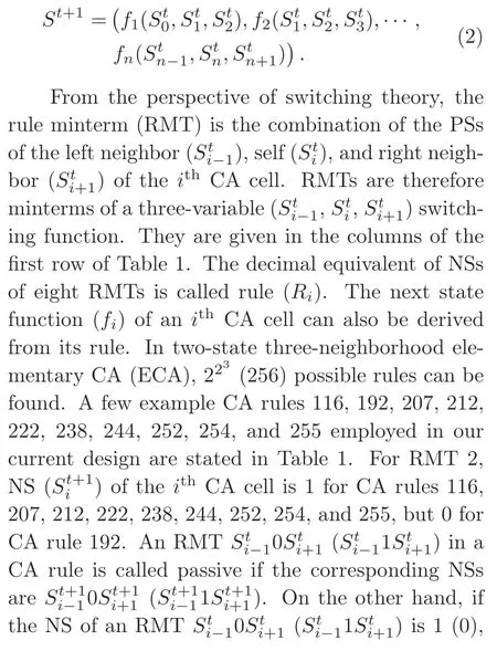
Cellular automata (CAs) are represented by a quadruple ofZD,S,M,andR,which are aD-dimensional lattice or cellular space,a set of states,a set of neighborhood vectors,and a set of local rules,respectively.Wolfram’s one-dimensional(1D)two-state CA or elementary cellular automaton(ECA)is used to model versatile discrete dynamical systems such as very large scale integration(VLSI),cryptography,networking,and cache systems.Those CA-based models are suitable for computer simulation with MATLAB,VHDL,and so on.The proposed fault-tolerant design is also developed around a subset of ECA that considers a special class of single-length-cycle single-or multipleattractor CAs.CA is analogous in operation to an autonomous finite state machine (FSM).Ann-cell binary CA stores discrete variable values of 0 or 1 at each time stept,which is referenced to the present state (PS) ().The next state (NS)of each cell at the next time step (t+1) is updated by the PSs of left neighbor,self (),and right neighborin a 1D three-neighborhood CA.The NS of theithCA cell is given in Eq.(1):

Therefore,the NSs of ann-cell CA can be represented by

The rule set of ann-cell CA is designated by a rule vectorR=<R1,R2,···,Rn >,where eachRi(i=1,2,···,n) represents the rule applied to each CA cell.If identicalRiis applied to all CA cells,the CA is a uniform one.It is a nonuniform(hybrid)CA for dissimilarRi’s applied to each CA cell.Finite CA with nonuniform and/or uniform null and periodic boundary(PBCA) conditions are considered for the current design.For null boundary CAs (NBCAs),the left terminal of the leftmost cell and the right terminal of the rightmost cell remain in the 0-state.For periodic boundary CAs (PBCAs),the right of the rightmost terminal is connected to the left of the leftmost terminal.CAs can be constructed withD-flipflops and combinational logic circuits(Fig.1).
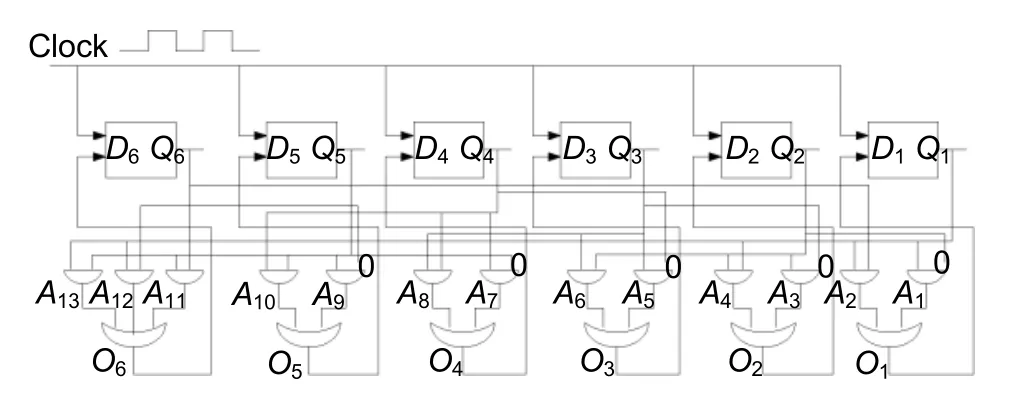
Fig.1 Block diagram of a six-cell nonuniform PBCA
The transition functions(fi’s)of all applied CA rules are given in Table 1.Thefi’s of each CA cell of the nonuniform rules 192and 207are constructed with combinational PS logic circuits for self,left,and right neighbors as given inrows 2 and 3 of Table 1 and detailed in Section 5.
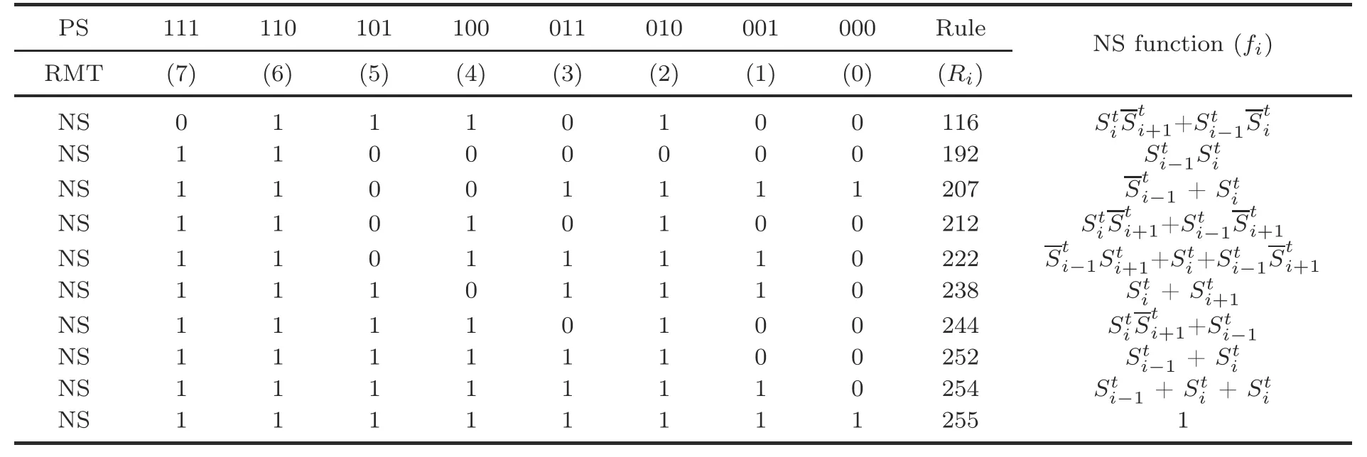
Table 1 Truth table
A state transition diagram (STD) and transition representation of the CA state space of five-cell PBCAs constructed withR1=<252,252,252,252,252>andR2=<238,238,238,238,238>are shown in Figs.2a and 2b,respectively.STDs are given to characterize CA states as reachable or unreachable and cyclic or acyclic states.Irreversible CAs have unreachable states,which cannot be reached from any other state (e.g.,1,2,4,8,9,13,16,20,21,22) but can have a few states with multiple predecessor states 30(predecessor states 20 and 28),23 (predecessor states 5 and 7),etc.,as given in Fig.2a.An attractor associated with a single state is called a single-length-cycle attractor or fixed-point attractor.Two single-length loops or cycles 0→0 and 31→31 are found in both STDs that form single-length-cycle attractors of the CAs.The depth of a CA is the maximum distance (measured with the number of states) traversed to settle down to an attractor state from any other state.In Fig.2a,the depth of the CA is 4(8→12→14→15→31).
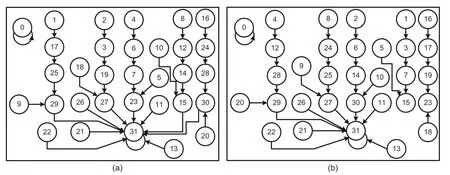
Fig.2 STDs of uniform PBCA <252,252,252,252,252>(a) and <238,238,238,238,238>(b)
The current design was developed around the theory of three-neighborhood null boundary and periodic boundary SACAs,TACAs,and MACAs.Nonuniform NBCAs with the rule pairs (192,207)and (254,255) are configured to detect the fault status of a memory word based on the following properties:
Property 1A ruleRican contribute to the formation of fixed point attractor(s) if at least one of the NSs of RMTs 0,1,4,and 5 is 0,and/or at least one of the NSs of RMTs 2,3,6,and 7 is 1(Saha et al.,2016).
Property 2Uniform rule 192 forms an SACA with all-0 single-length-cycle attractor only in its threeneighborhood null-boundary construction.
Property 3Nonuniform three-neighborhood NBCA rule pair (192,207) is converted to a TACA from an SACA for hybridization in a single cell or multiple cells.It forms two all-0 and all-1 singlelength-cycle attractors only.
Property 4Uniform three-neighborhood NBCA rule 254 incorporates two all-0 and all-1 single-length-cycle attractors and thus becomes a TACA.
Property 5The uniform TACA with rule 254(Ro) is converted to an SACA when it is hybridized with rule 255 (Rh) at a single cell or multiple cells.In alternate designs of fault detection and diagnosis(Sections 3 and 4),few uniform PBCA and NBCA rules can be used.Stated CA rules satisfy the design requirements as per the given properties:
Property 6A three-neighborhood uniform PBCA with rule 238 forms a TACA because it forms two all-0 and all-1 single-length-cycle attractors for passive RMTs 0 and 7.
Property 7A uniform PBCA with rule 252 forms a TACA in its 1D three-neighborhood construction.It forms two all-0 and all-1 single-length-cycle attractors for RMTs 0 and 7 as they are passive.
Property 8A uniform NBCA with rule 116 forms a TACA in its three-neighborhood construction.It forms two single-length-cycle attractors for RMTs 7 and 0 as they are active and passive,respectively.
Property 9A uniform three-neighborhood NBCA with rule 244 forms an MACA.It forms all-0,all-1,and other single-length-cycle multiple attractors for RMT 5 being active and RMTs 0 and 7 being passive.
Property 10The three-neighborhood uniform NBCA rule 222 forms an MACA.It has all-0 and other single-length-cycle multiple attractors for RMTs 0,5,and 7 being passive.
Property 11Uniform NBCA rule 212 forms a TACA with two all-0 and all-1 single-length-cycle attractors for RMTs 0 and 7 being passive.
A reachability tree (RT) is a binary tree constructed to characterize the states of a CA state space.CA states can be characterized as nonreachable,reachable and acyclic,or reachable and cyclic states using an RT.In this fault-tolerant design,a subset of ECAs is chosen,having only singlelength-cycle single or multiple attractors.An RT can be used to detect those single-length cycles efficiently.An example tree with a four-cell CA with uniform CA rule 244 is shown in Fig.3.The nonreachable states are 1,2,4,5,7,9,10,and 13.These states do not contribute to form cycles.The RMT sequence obtains a reachable state.Reachable states may form cyclic states.Cyclic states can set up single-length-cycle attractor(s) (e.g.,0→0) if their RMT sequence(e.g.,<0000>)evolves through passive RMTs only.
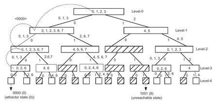
Fig.3 Reachability tree for the four-cell NBCA rule vector <244,244,244,244>
3 Fault-tolerant ReRAM design
The motivation of the current research is to propose a CA-based dynamic fault-tolerant design methodology at block-level granularity for general fault conditions.Memory blocks are assumed to have a universal set ofNcells,indexed withc(0),c(1),...,c(N -1) with the possibilities of the cell(c(i)) status as non-faulty (NF),stuck-at-0 (S-A-0),and stuck-at-1 (S-A-1).The fault status ofc(i) can be SAR,SAW,and NF,as compared to the input data(D).This implies that if the faulty cell(c(i))is in the S-A-0 status and input data (D) is 1,or vice versa,the status ofc(i)is SAW.
However,if faultyc(i)is in the S-A-1 status andDis also 1,or vice versa,the cell status is SAR.For an NF or SAR cell,the data can be directly read fromc(i) without data rectification,being indistinguishable asDand stuck-at value.Therefore,detection of SAW cells is the primary requirement of the fault-tolerant design.To test an SAW cell,data(v) written toc(i) is stored back inV.The SAW status is exhibited when data to be stored (Dorv)and retrieved data (V) are not equal (Table 2).IfvandVare identical,thenc(i) may be NF or SAR.Now,to test thatc(i)is in the SAR status,the complemented data is stored inc(i) and retrieved toVc.For equalvandVc,the status ofc(i) is inferred as SAR.For unequal values ofvandVc,thec(i) is NF as explained in Table 2.
3.1 Fault detection circuit employed in ReRAM
The test logic can be implemented using a combinational logic circuit succeeded with CA.Each memory cell status can be identified by checking the output bitsOjof XOR2andOkof XNOR1gates,respectively,as shown in Fig.4.Dis inputted through the controlled buffer (XOR1).Control signal(Dcon)producesDandDaccording to the comparison operation.The SAW status ofc(i) can be sensed byOj,which gives a comparison result ofVandv.Forc(i) to have the SAW status,Ojis 1.IfOj=0,then the status ofc(i) is either SAR or NF and is rechecked byOkfor the exact status.XNOR1comparesVcandv.Forc(i)to have the SAR status,Ok=1,and for the NF status,Ok=0.
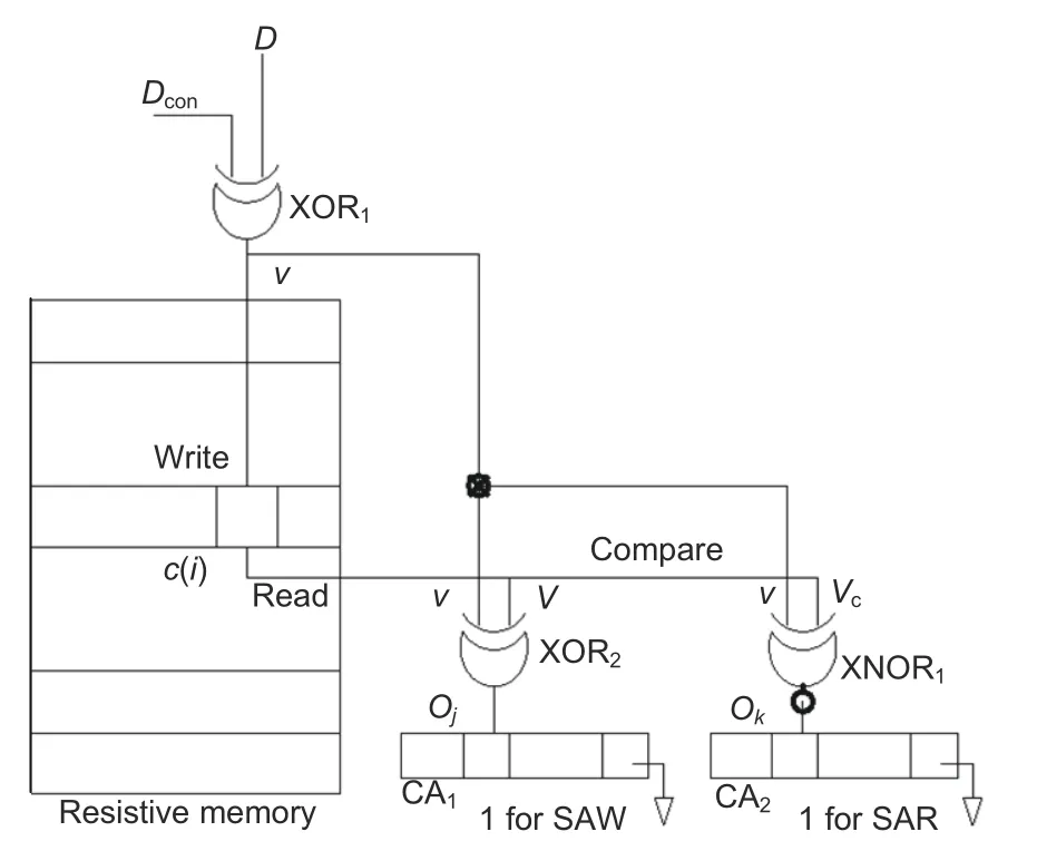
Fig.4 Identification of the fault status of the memory block (Sarkar et al.,2017)
A memory block can have (1) NF cells only(BNF),(2) SAR and NF cells but no SAW cell(BSAR),(3)SAW and NF cells without any SAR cell(BSAW),or (4) SAR,SAW,and NF cells (BSARW).For runtime fault detection of a memory block,twoN-cell CAs,namely CA1and CA2,are employed.By sensing the least significant bits (lsbs) of the attractor states of both CA1and CA2,the fault status inb(i)can be exhibited.
If thec(i) status bit is 0,the cell rule isRNF(192).The status bit forRSAWorRSAR(207) is 1.Therefore,for an NF memory word,the rule set is uniform for CA1(RCA1) and CA2(RCA2) withRNF(192),as shown in Table 3.After thetime step,it settles down to the attractor state (0→0),whose lsb(st)is 0 as given in Table 3.In case of SAR and SAW,both CAs (CA1and CA2) are configured with a hybrid rule ofRNF=>192 andRSAR=>207 and/orRSAW=>207.Now,if the CA is run for thetime step,it settles down to the attractor state with lsb 1(e.g.,attractor state 7 or 5).IfO(j)O(k)=1,the encoded rule 207 is set asO(j)=1=set rule 192 for theithcell of CA1(CA2) (Table 3).

Table 2 Tabular representation of fault-tolerant design steps

Table 3 Tabular representation of fault detection with a nonuniform NBCA rule pair (192,207)
To improve the misprediction rate (Mp),another hybrid CA rule pair can be employed.The fault status is tested by the previously mentioned two consecutive read-write and compare-check operations.In an alternate design,the CA rule forRNFis 254,whereasRSAR(RSAW) is 255.The same fault-check process sets theithcell rule.RSAR(RSAW) is set forO(j)=1 (O(k)=1) as 255 andO(j)=0 (O(k)=0) asRNF254,as shown in Table 4.Therefore,CA1(CA2) is a uniform CA with rule vector <254,254,254,...>for a non-SAR(non-SAW) memory word.For all other fault conditions,CAs are configured with hybrid CA ruleRNF(254)andRSAR(RSAW)(255)(RCA1,RCA2) (Table 4).During memory testing,CA1(CA2) is initialized with an all-0 seed.For each non-SAR/non-SAW word,both CAs are configured with uniform ruleRNFas 192(254)and allowed to run for a single time step (t=1).For NF words,CAs remain in the all-0 state.The test logic enforces the CA configuration to be hybridized withRSAR(RSAW) as 207(255) when faulty words are encountered.It jumps to a non-zero state within a single time step(Tables 3 and 4).For any subsequent faulty or non-faulty words,the hybrid CA continues to run for single time steps.Reachingb(i)’s last word,CAs are allowed to settle down to an attractor state.The status ofb(i)is tagged by the lsbs of the attractors(st(0)and st(1))as to (1) 00 forBNF,(2) 01 forBSAR,(3) 10 forBSAW,and(4)11 forBSARW(Tables 3 and 4).
3.2 Alternate design option for fault detection
Though hybrid SACA rules 192 and 207 as well as 254 and 255 can appropriately classify the fault status ofb(i),there is room for performance improvement.Instead of nonuniform CAs,a few uniform NBCAs and PBCAs can be employed in fault detection.Employed CAs are required to settle into different single-point attractors (Attr’s) for faulty and NF blocks.Further,the best possibility is to find an even rule CA configuration that settles into an attractor state of lsb 0 for NFb(i) and lsb 1 for the faultyb(i).In an alternate design option,TACA and MACA are used to avoid the rule-set complexity of SACA.
For simple CA design,uniform NBCA with the TACA configuration is employed for the fault detection circuit.To test the presence of an SAR (SAW)cell,the test logic remains unaltered in the alternate design (Section 3.1).Uniform TACA rules 116 and 244 are found to be appropriate to reduce the design complexity (Table 1).For CA rule 116,for a faultyb(i),the CA settles down to a single-point attractorAttr1→1 of lsb 1.It settles down toAttr0→0 of lsb 0 for an NF block.For CA rule 244,the fault status can be detected byAttr1→1 with lsb 1,whereas the NF status is indicated with a single-point attractorAttr0→0 with lsb 0.The uniform MACA rule 212 can indicate the fault status of a memory word having single-point attractorsAttr’s 1→1,5→5 of lsb 1.The uniform MACA rule 222 can also indicate the fault status of a memory word having multiple single-point attractorsAttr’s 11→11,13→13,15→15 with lsb 1.Both CAs indicate NFc(i)withAttr0→0.Uniform PBCAs can also be employed in fault detection circuits maintaining the aforesaid test logic(Section 3.1).Uniform TACA rules 252 (Fig.2a)and 238 (Fig.2b) are found to be more appropriate for fault detection.The above CAs (CA1and CA2) are allowed to run to settle down to attractor states.The lsbs of attractor states are collected to obtain the faulty status ofb(i) (Table 4).The attractorAttr(15→15) with lsb 1 flags for the SAR or SAW status and the NF status is indicated by a single-point attractorAttr(0→0) with lsb 0.Summarization reveals that the idea of fault tolerance is implemented in three steps:(1) identification of the nature of faulty cells through test logic,(2)selection of uniform or nonuniform,PBCA or NBCA rule with the rule selection logic,and (3) classification ofb(i)as per the status of thec(i)’s in a CA-based block categorization (CABC) logic.The working steps of the fault detection logic,rule set logic,and CABC are detailed in Table 2.

Table 4 Tabular representation of fault detection with a nonuniform NBCA rule pair (254,255)
Fault detection is a pre-requisite of all groupbased static RDIS(Melhem et al.,2012)or dynamic SAFER(Seong et al.,2010)fault diagnosis schemes.The described fault detection unit can be implemented separately to detect a fault condition ofb(i)only or collectively as a built-in sub-unit of the fault diagnosis process.Further,because the cell status(SAR or SAW) can change with the input data,the fault status can be saved in a separate on-chip cache unit to avoid redundant writes of the compare-check process.
3.3 Block diagram of a fault-tolerant system
Tentative blocks of fault-tolerant ReRAM hardware design are illustrated in Fig.5.The system implements fault detection for diagnosis and includes up to fault recovery logic with four logically connected units:(1)The fault identification(detection)logic unit checks the status of eachc(i)for all memory blocks.This unit categorizes and puts a tag(st)in eachb(i).(2) Twon-bit registers forn-bit words are used to record the status of each memory cell under test.The outputs of those buffer registers are connected to the input of the fault diagnosis unit.BSAWandBSARWpass through fault diagnosis units using cascaded multiplexers (MUX-1,MUX-2,and MUX-3)for further processing.MUX-1 and MUX-2 simply passBSAR/BNFandBSAW/BSARWas per selection lines (sel1,sel2).MUX-3 differentiates SAW and non-SAW blocks,which either pass through the diagnosis unit or pass directly to the read/write(RD/WR)buffer.One DEMUX(DEMUX-1)is connected to the output of MUX-3.It passes the blocksBSAR/BNFthroughY0andBSAW/BSARWthroughY1as per selection line (sel4).Y0is directly connected to the RD/WR buffer.The selection logics of MUX-1,MUX-2,MUX-3,and DEMUX-1 are shown in Fig.5.It is implied that,for st=00 and 10 and st=01 and 11,sel4=>0 and 1,respectively.The fault diagnosis block is composed of partitioning,data mapping,and recovery logic units.The fault diagnosis unit takes input from the fault detection unit through theY1output of DEMUX-1.Finally it passes corrected data to the RD/WR buffer.(3)The RD/WR buffer contains the correct(readable) data regardless of any fault condition.(4) ReRAM is the device under test(DUT).
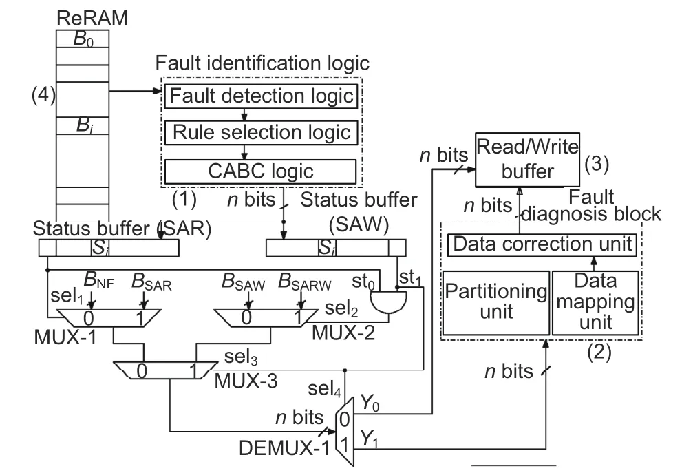
Fig.5 Tentative block representation of multi-bit stuck-at fault-tolerant system design
4 Fault diagnosis methodology
The fault detection unit detects the presence of faults within a block,whereas the fault diagnosis unit checks the exact fault position of SAW (SAR)cells within a block (BSAWorBSARW).IfSSAR(i)(SSAW(i))=1,the status ofc(i)is SAR(SAW)and 0 for the NF cell.The detected fault positions of SAW cells are inputted to the data correction unit and explained in Section 4.3.Fault diagnosis is implemented in three steps:(1)The first step is recursive partitioning of data blocks.The partitioning information is saved in registers for data mapping.(2)Reshaping is done on a partitioned 1D array into a 2D array.Group information along with partitioning fields is further stored in a lookup table (LUT)for recovery logic.(3) The position of a stuck-at faulty cell in a group(partition)is obtained through a CA-based method.
4.1 Recursive partitioning technique
For ann-bit block,the partitioning unit formskgroups by taking even or odd cell indices separately.Recursive partitioning considers single-bit faulty groups for fault position detection.The newly occurring fault to a pre-existing faulty group enforces regrouping.All single-bit faulty groups are formed with sub-multiples of block-length (n).The partitioning scheme uses thec(i) index bitsIm-1,Im-2,···,I1,I0.The default partition is represented by even and odd groups by considering partition position (p)=1 and based onI0(0 for even and 1 for odd).The occurrence of a fault in a singlebit faulty group enforces re-partitioning by groupdiscriminator logic.For an example design with a 16-bit data block,there are four index bits (m=log2n).For default groups,the number of elements(c(i)’s) is eightfor each group.Two faultyc(i)’s in default partitions may occur as follows:(1) in the same group P-E or P-O,requiring repartitioning,or(2) in different groups P-E and PO,not requiring any change in partition.IfF1is assumed to be inc(8) with indexI3I2I1I0=1000 andF2is inc(3)with indexI3I2I1I0=0011,default partitioning is maintained,because the faults are in P-E and P-O,respectively.IfF3is considered atc(0),its partitioning field is the same asc(8).P-E is repartitioned to P-EE and P-EO.IfF4occurs atc(15),P-O is repartitioned as P-OE and P-OO to maintain single faults in odd partitions.
The partitioning fields of even and odd group structures take the form of a binary code tree(Fig.6).Odd and even group partitioning fields are encoded and saved in the tree structure using the convention of even partition fieldPE=0 and odd partition fieldPO=1.However,the left branch always represents even,whereas the right branch is for odd partitioning information.The tree may take a form of a complete or incomplete binary tree structure depending on the number and position of faults.Using maximum likelihood decoding,partitioning field information can be retrieved at the time of recovery.
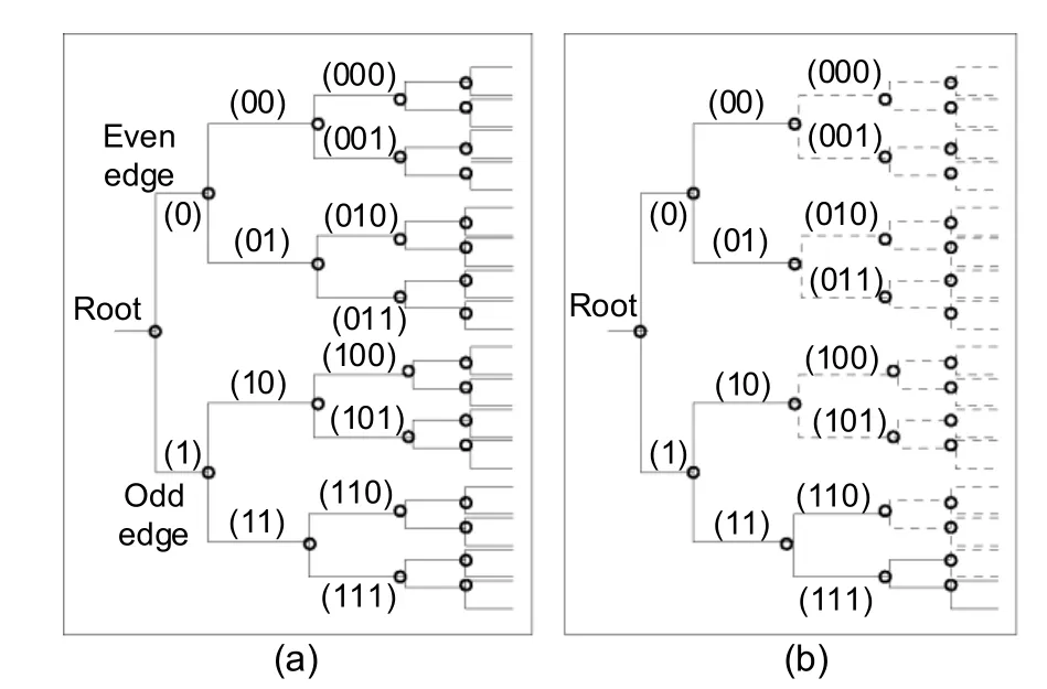
Fig.6 Code tree structure for fault condition:(a)complete tree;(b) incomplete tree
A total of log2kbits are required to represent thekgroups.Identification of the faulty cells in the same group is required to re-adjust the partitions.Comparing the faulty cell’s index bits in the default partitionI0=0 or 1,the even-odd group can be distinguished.Similarly,even-even/even-odd (EE or EO) and odd-even/odd-odd(OE or OO)groups are fixed with the index bitsI1I0=00 (10) andI1I0=01(11).Therefore,the 1st,2nd,3rd,and up tonthlsbs are compared to determine re-partitioning.By inspecting and comparing index bitsIm-1···I0of faulty cells,the group discriminator creates control logic for memory partitioning(Fig.7a).

Fig.7 Logic circuit implementation of the group discriminator logic (a) and data recovery logic (b)
4.2 Data mapping logic
The contents of the status buffer registers(SSAWandSSAR) andPEandPOpartitioning information are fed to the data mapping logic unit.At this stage,a 1D arraySSAW(SSAR) of lengthnis mapped in a 2D array (n=n1×n2) (Sarkar et al.,2017).For cell indexC(j,k),jandkare denoted asandk=i(modn2),respectively,wherei=jn2+k.The mapping of a 1D array of block lengthn=16 to a 2D array of 4×4 (BSARW) is shown in Fig.8a.The mapped 2D array shows only theBSAWstatus in Fig.8b,whereas theBSARstatus is shown in Fig.8c.The intersection pointC(j,k)=1 if the corresponding cell is in SAW (SAR) (i.e.,BSARW(i)=1);otherwise,it is 0.
4.3 Fault position detection using CA
A CA is employed to test each row and column to detect the exact position of a faulty cell.The design step is proposed around nonuniform and/or uniform CAs.Then1-cell (n2-cell) CAs are used for each row (column) of the 2D array.A uniform rule vector <254,254,254,...>is configured for a non-faulty row(column),which settles to an attractor state of lsb-0 as per Property 4.The CA rule is hybridized for the presence of a faulty cell in a row(column).Contents of a row and/or column are considered as seeds of row (column) CAs.For example,a faulty cell in a rowRi=[0,0,0,···,1]and columnCl=[1,0,0,···,0] will set a nonuniform rule vector <254,254,...,255>and <255,254,...,254>for the row and column,respectively.A nonuniform CA settles to an attractor state of lsb-1 as per Property 5.The lsbs of the attractors of row and column CAs are collected inVxandVyregisters.A faulty cell index (C(j,k)) is found by the intersection points ofVxandVy(Fig.8).Uniform PBCA rules 238 or 252 can also be used for this step of fault diagnosis.However,n1-cell (n2-cell) CAs are applied in the aforesaid technique to each row (Ri,Rj,Rk,Rl)and column (Ci,Cj,Ck,Cl) (Fig.8).These PBCA rules form TACA construction as per Property 6 and Property 7,to settle to the alternate attractors,thus enabling fault position detection.
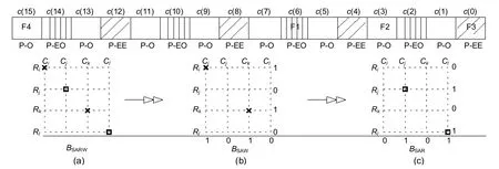
Fig.8 Data mapping logic for the partitioned 1D array to 2D array for BSARW (a), BSAW (b),and BSAR (c)
The partial hardware realization of recovery logic is shown in Fig.7b.Row (column) decoders take input fromVxandVy.The row and column decoders enable control and multiplexer selection of recovery logic.If ANDi=0,the cellC(j,k) is in NF or SAR.No data correction is required.The stored value is placed in the read/write buffer.For ANDi=1,C(j,k) is in SAW.The data is inverted by a controlled buffer (XORi) and saved in an RD/WR buffer.
5 Performance analysis
Cell endurance is affected by repetitive writes,caused by uneven distribution of workload among cores and malicious attacks.The proposed scheme considers uneven workload distribution that produces spatially scattered stuck-at faults (Sarkar et al.,2020).Variable cell lifetime is also noticed,because few memory blocks are frequently written whereas others are seldom or never used.SAFER(Seong et al.,2010)and RDIS(Melhem et al.,2012)rely on Monte Carlo simulation to observe cell reliability over repetitive writes.Cell lifetime variation against the number of writes shows a probability density function (PDF) of Gaussian distribution as given by

NORM.DIST(value,mean,stddev,c) is used to interpret cell lifetime variation over the number of writes within the range 1×10⁸–2.6×10⁸with variance (σ2) 1×10⁷and mean lifetime (μ) 1×10⁸writes (Fig.9).
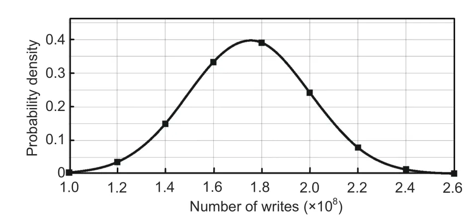
Fig.9 Cell lifetime variability vs.the number of writes (Seong et al.,2010)
The write endurance problem is often addressed with aggressive wear leveling and proactive error masking(Qureshi et al.,2009).Wear leveling is used to eliminate nonuniform writes.It is achieved mainly through address remapping techniques(Sarkar et al.,2020).Therefore,feasible fault-tolerant design needs to be complementary to wear-leveling schemes for cell lifetime improvement.Unlike SAFER and RDIS,this scheme is compatible with wear-leveling schemes.As it can be effectively applied along with wear-leveling schemes,each memory cell is assumed to have an equal probability of being written.
5.1 Analysis of CA tools
CA tools are used to detect stuck-at faults(SAW or SAR)of memory blocks(b(i)’s).Each block(havingncells) is operated independently in fault detection.Variousn-cell three-neighborhood CAs are configured in fault detection logic(Section 3).State transitions of the CA state space are observed in MATLAB version R2014a.Each CA configuration is run on a 64-bit(Win 64)Intel®,CoreTMi3-6006U processor @2.00 GHz×4,64-bit operating system.Null boundary and periodic boundary conditions are configured for a programmable CA structure using MATLAB.Starting from the all-0 state as an initial condition,all possible combinations of PS () and NSstates within the CA state space evolve.For ann-bit generic CA with various SACA,TACA,and MACA rules,generated present states and next states are tabulated through built-in MATLAB functions.STDs are formed and single-length-cycle attractor states are extracted from them.State space evolution is also observed for CA depth and to find the non-reachable states that are not contributing to the formation of any single-length-cycle attractor.
Stuck-at faults(SAW or SAR)are primarily detected through alternate pairs of NBCAs.Nonuniform cell rule pairs(254,255)and(192,207)(Section 3) are used.The uniform NBCA rule 254 has two single-length attractors (all-0 and all-1).The hybridized rule of 254 and 255 is found to be an SACA rule that settles only to a single attractor state of 15→15 with lsb 1 (detecting the faulty block status).The nonuniform NBCA rule pair (192,207)may form an MACA in multi-bit faulty cells.Therefore,a nonuniform CA with the rule set 254 and 255 is advantageous instead of using the CA rule set 192 and 207 due to increased speed and reduced misprediction rate (Table 5).
Alternatively,uniform NBCA rules 116,212,222,and 244 are used in fault-tolerant design.These CA rules satisfy the requirements of fault detection as per Properties 8,9,10,and 11,respectively.These designs are compared in Table 6 with respect to the misprediction rate and depth of CA (D).These design options can also provide 100% fault tolerance although the speed of execution is different in each case.The application of uniform CA rules 116 and 222 can provide more speedup (D=3) than the alternate CA rules 212 and 244 (D=4).CAs with uniform rule vectors 116 and 244 settle to an all-0 attractor (0→0) with lsb 0 and a 1→1 attractor state with lsb 1 to indicate the non-faulty or faulty status ofb(i) (Figs.10a and 10b).Uniform CA rule 212 has an all-0 attractor along with another two attractors with lsb 1 (1→1,5→5) (Fig.11a).Uniform CA rule 222 settles to an all-0 attractor (0→0)with lsb 0 and 11→11,13→13,and 15→15 attractor states with lsb 1 (Fig.11b).
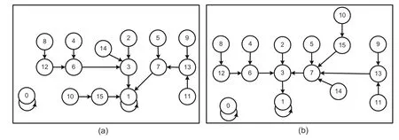
Fig.10 STD of four-cell uniform NBCA rules 116 (a) and 244 (b) in TACA construction
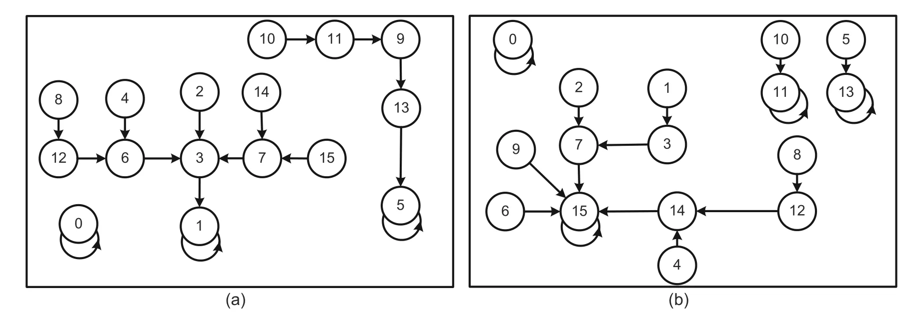
Fig.11 STD of four-cell uniform NBCA rules 212 (a) and 222 (b) in MACA construction
All NBCA rules are described in four-cell structures in this example design.The numbers of singlelength-cycle attractors for variablen-cell CA structures are compared in Fig.12a.The number of single-length-cycle attractors marginally increases in CA rule 212,whereas CA rules 116 and 244 have the same number of single-length-cycle attractors.CA rule 222 has a larger number of single-length-cycle attractors than others.It will create design complexity for larger block size(n).Uniform PBCA rules 238 and 252 can be employed in alternate design solutions and those performance parameters are also compared in Table 6.Both CAs have only two attractor states 0→0 and 15→15 with alternate lsbs 0 and 1 to detect the faulty or NF status(Figs.2a and 2b).All design options using various uniform PBCA or uniform/nonuniform NBCA CAs when initialized with an all-0 (all-1) seed settle to an attractor state with lsb 0 (1) after thestep.Therefore,identification of the SAW,SAR,or NF status word requires additional T states.The number of T states required to detect the fault status is given in Fig.13.Employing TACA rules 238 and 252 takes additional three T states (maximum) to detect the presence of faults.

Fig.12 Number of single-length-cycle attractors for different uniform NBCA rules (a) and the test overhead in fault detection in terms of logic gates (b)
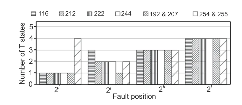
Fig.13 Speed of operation for uniform or nonuniform CA rules

Table 5 Comparative analysis of fault detection with CA rule pairs (192,207) and (254,255)

Table 6 Comparative state analysis report of fault detection with various uniform CA rules
The fault detection test logic circuit requires various rule-specific logic gates to check the status of faulty cells as described in Section 3.The required numbers of XOR and XNOR logic gates (n)to check and compareVandvandVcandvremain unaltered for all employed CA rules.However,the various design approaches using the nonuniform CA and uniform CA (as per Table 1) require a varied number of AND,OR,or NOT logic gates(Fig.12b).The design with 254 and 255(192 and 207)stores the SAR and SAW status using a nonuniform rule setting.Therefore,for ann-cell CA,the configurable CA options are 2n(here 24).A few such instances with nonuniform rule vectors are shown in Table 5.The time of execution and the misprediction rate are derived from STDs (Saha et al.,2016).Additional uniform and nonuniform rule setting logic requires a maximum number of gates for CA rules 192,207,254,and 255 compared with other uniform CAs,although CA rule pair (254,255) requires far fewer gates than the rule pair(192,207)(Fig.12b).
The fault diagnosis unit also uses CA-based fault position detection logic (Section 4).Design requirements are as follows:(1) The presence of faults is to be detected through the single-lengthcycle nonzero attractor(s);(2)The absence of faults is detected through the single-length-cycle zero attractor state.For the presence of 1 (for SAW or SAR cell) in a row (column),the CA with CA rule 254 is hybridized by CA rule 255.The uniform or nonuniformn2-cell (n1-cell) CAs (254 and 255) follow Properties 2,3,4,and 5,respectively,which satisfies the design requirements.PBCA rules 238 and 252 can also be used in fault diagnosis because they follow the properties of TACA (Properties 6 and 7)to fulfill the design requirements (zero and nonzero single-length-cycle attractors 0→0 and 15→15)(Table 6).
5.2 Analysis of space overhead
A trade-offbetween tolerable faults and space overhead is essential for a feasible multi-bit fault diagnosis unit design and implementation.Therefore,a CA-based design not restricted by the number of tolerable faults is proposed here.The memory block under consideration hasnmemory cells withkfaulty bits.The space overhead of the proposed fault-tolerant design(Sms)is given by

Smsis sensitive to the number of faults and the block size (Fig.14a).The space overhead shows linear growth with the increased number of faults and the block of fixed size.It is reduced with a variable block size when the number of faults is fixed.The space overhead of SAFERkis given by

For example,to protect a block size of 512 bits and for SAFER 32,the space overhead is 10.93%(Fig.14b).This requires higher space overhead than the proposed scheme to protect a memory block having the same number of faults (Fig.14b).SAFER(Seong et al.,2010) is also limited by the number of tolerable faults as log2n+1.RDIS(Melhem et al.,2012)can tolerate a maximum(RDIS_max)number of faults given bySimilarly,the space overhead for RDIS is given by

The RDIS scheme needs an elevated percentage of space overhead to tolerate a large number of faults.A comparison of SAFER and RDIS is shown in Fig.14b.As can be seen,recursive re-grouping is found to be more advantageous than others based on tolerable faults and space overhead.

Fig.14 Space overhead vs.the number of tolerable faults (a) and comparison with RDIS and SAFER (b)
A CA-based multi-bit fault diagnosis and recovery scheme was proposed in Sarkar et al.(2017),but the scheme assumed a limited number of writes to assure 100%fault tolerance.It is also limited by the number of tolerable faults as log2n+1.The proposed CA-based recursive logical partitioning technique removes restriction on tolerable faults with reduced overhead(Fig.15a).

Fig.15 Space overhead comparison with Sarkar et al.(2017)’s scheme (a) and ECP-based scheme (b)
The proposed scheme is also compared with an error correction pointer (ECP) based fault diagnosis scheme (Fig.15b).For example,to tolerate six faults in a memory with a block size of 1024 bits,the space overhead is 6.54%.Overhead for the ECP-based scheme monotonically increases with the increase of the number of tolerable faults.

The proposed scheme requires almost marginal changed space overhead with a smaller number of tolerable faults.Therefore,the ECP-based scheme incurs much higher space overhead than the proposed scheme (Fig.15b).
Space overhead increases in full system implementation of the proposed scheme,as is the case in state-of-the-art schemes.Secondary space overhead per memory block is derived from Eq.(8).Because it is assumed that each group must contain a single fault,kbits are required to identify which groups are carrying faulty bits.Status bits are tagged to flag the presence of the nature of fault(s) in a block.Complete or incomplete code tree structure requires log2nbits to encode each of the partitioning information of even and odd groups.The row (column)elements ofBSAWorBSARW(memory cells)are represented by the CA cells constructed withD f/fsand combinational logic circuits.The faulty cell position detection in a row (column) with a CA rule pair of 255 and 254 or other nonuniform CA rules requires additional storage for identification of faulty groups.VxandVyare the row and column buffers that keep the lsbs that act as decision bits,respectively.The intersection information of the row/column of the faulty cell position([C(j,k)]) adds storage burden.

Additional space overhead(Sadd)increases with the increase of the number of tolerable faults(Fig.16a) and decreases with the increased block size(Fig.16b).

Fig.16 Secondary storage overhead vs.the number of tolerable faults (a) and block size (b)
The reshaped 2D data matrix has multiples ofm×n(e.g.,4×4 and 8×8)row versus column elements and the CA structure needs to vary according to dynamic partitions.The CA employed in fault diagnosis must be a programmable CA (PCA) with a variable number of cells (n/2p).Although it does not add any additional storage burden,the design complexity of PCA must be handled for recursive grouping of an increased number of faults.Further,the fault-tolerant design unit needs to complement with wear-leveling schemes to improve memory cell endurance (Seong et al.,2010) and combat security threats (Sarkar et al.,2020).Wear leveling puts an address translation layer among the logical address,intermediate address,and physical address.This micro-architectural design unit is required to be embedded within the memory controller because it works along with wear-leveling schemes.
6 Conclusions and future work
Unreliable cell operation due to multi-bit stuckat faults limits the application of ReRAMs in CMPs.The proposed scheme assures 100%fault tolerance in spite of spatially scattered complex multi-bit stuckat faults.Because it is a runtime strategy,it can also cope with the variable cell lifetime issue.Here,the recursive partitioning technique is used to diagnose SAW or SAR cells at block-level granularity.It is effective for general fault conditions and for any number of tolerable faults.The unique test architectures are developed around SACA,TACA,and MACA rules with three-neighborhood NBCA or PBCA construction.Various options increase simplicity and flexibility in design and implementation stages of detection and/or diagnosis.An optimized design solution using alternate CA rules reduces the space overhead in spite of increasing the block size.
The proposed group-based diagnosis scheme assumes a single fault in each partition.Single-bit faulty groups can be modified to create multi-bit faulty groups that can tolerate more faults with the same number of partitions.This scheme can be an extension of the current CA-based diagnosis.The concepts of uniform and nonuniform PBCA or NBCA rules can also be applied for complete design solutions of single-and multi-bit group-based fault diagnosis schemes in the future work.Further,a CA-based SEC-DED technique can be implemented in the single-bit faulty group based scheme.The recovery logic will in turn reduce the design complexity and increase the flexibility of PCA application in diagnosis.
Contributors
Sutapa SARKAR designed the research,collected and processed the data,and drafted the paper with formal analysis.Biplab Kumar SIKDAR helped organize the paper.Sutapa SARKAR and Mousumi SAHA revised and finalized the paper.
Compliance with ethics guidelines
Sutapa SARKAR,Biplab Kumar SIKDAR,and Mousumi SAHA declare that they have no conflict of interest.
 Frontiers of Information Technology & Electronic Engineering2022年7期
- Frontiers of Information Technology & Electronic Engineering的其它文章
- Perspective:Prospects for multi-agent collaboration and gaming:challenge,technology,and application*
- Institutionalized and systematized gaming for multi-agent systems
- Efficient decoding self-attention for end-to-end speech synthesis*
- Enhanced solution to the surface–volume–surface EFIE for arbitrary metal–dielectric composite objects*
- Review:Light field imaging for computer vision:a survey*#
- Cooperative planning of multi-agent systems based on task-oriented knowledge fusion with graph neural networks*
