Review:Light field imaging for computer vision:a survey*#
Chen JIA,Fan SHI†‡,Meng ZHAO,Shengyong CHEN
1Engineering Research Center of Learning-Based Intelligent System(Ministry of Education),Tianjin University of Technology,Tianjin 300384,China
2Key Laboratory of Computer Vision and System(Ministry of Education),Tianjin University of Technology,Tianjin 300384,China
Abstract: Light field (LF)imaging has attracted attention because of its ability to solve computer vision problems.In this paper we briefly review the research progress in computer vision in recent years.For most factors that affect computer vision development,the richness and accuracy of visual information acquisition are decisive.LF imaging technology has made great contributions to computer vision because it uses cameras or microlens arrays to record the position and direction information of light rays,acquiring complete three-dimensional(3D)scene information.LF imaging technology improves the accuracy of depth estimation,image segmentation,blending,fusion,and 3D reconstruction.LF has also been innovatively applied to iris and face recognition,identification of materials and fake pedestrians,acquisition of epipolar plane images,shape recovery,and LF microscopy.Here,we further summarize the existing problems and the development trends of LF imaging in computer vision,including the establishment and evaluation of the LF dataset,applications under high dynamic range (HDR) conditions,LF image enhancement,virtual reality,3D display,and 3D movies,military optical camouflage technology,image recognition at micro-scale,image processing method based on HDR,and the optimal relationship between spatial resolution and four-dimensional (4D)LF information acquisition.LF imaging has achieved great success in various studies.Over the past 25 years,more than 180 publications have reported the capability of LF imaging in solving computer vision problems.We summarize these reports to make it easier for researchers to search the detailed methods for specific solutions.
Key words: Light field imaging;Camera array;Microlens array;Epipolar plane image;Computer vision
1 Introduction
Light field (LF) imaging is a type of computa‐tional photographic technology.In contrast to twodimensional(2D)imaging methods,a light field cam‐era (LFC) can record the intensity and direction of each ray,and multiple views of the scene can be captured in one exposure.This capability brings new possibilities for post-processing of an image.Many studies have proven that LF imaging can greatly improve the capabilities and performances of com‐puter vision technologies,including digital refocus‐ing,image segmentation,shape recovery,and saliency detection.
LF imaging technology was pioneered by Lipp‑mann (1908).Using an early LF imaging method called integral photography (IP),he proposed that true stereo images can be reconstructed based on the reversibility principle of light rays.Later,Gershun(1939) first defined the distribution of light rays as a model.Then,Adelson and Bergen (1991) improved this definition and proposed to name this model“the plenoptic function”based on the position,angle,wave‐length,and time of each light ray.Numerous systems of LF acquisition have been built,most of which are composed of multi-cameras or camera arrays.For these systems,the cameras or camera arrays are dis‐tributed on a planar surface,and each camera records the radiance of light rays on a single point.The first handheld LFC,proposed by Ng et al.(2005),was portable,cheap,and useful.In recent years,LFCs such as the Lytro and Raytrix,have been made avail‐able commercially.These cameras make it easy to capture the information of the whole LF for common users,and thus have attracted much interest.Because of its outstanding performance,LF imaging technol‐ogy has great potential in various fields of computer vision research and application,such as biometric detection and robotics vision.
2 Overview of related works
2.1 Summary
In the 120-year history of LF imaging,the rapid application of optical field imaging technology to com‐puter vision has occurred mainly in the last 25 years.Therefore,the research studies summarized in this report were selected primarily from this period.The main developments over that period were as follows:(1)from 1996 to 2010,initial development and appli‐cation of LF imaging;(2) from 2010 to 2015,rapid development of LF imaging in computer vision re‐search;(3) from 2015 to 2021,peak period of LF imaging.To our knowledge,however,there have been few reviews of research on LF imaging calculations,and very few focusing on the application of LF imag‐ing to computer vision.
Recently,there has been a rapid development of LF imaging technology in computer vision.In partic‐ular,since 2015,the commercial promotion,devel‐opment,and popularization of LFCs have accelerated.Additionally,many innovative computer vision theo‐ries and models have been proposed and applied,such as LF depth estimation theory,LF super-resolution theory,and face recognition models.We believe that it is important to summarize the development of LF imaging technology in computer vision,to provide information for researchers.
After LFC was made available commercially in 2005,this topic has attracted many researchers.How‐ever,reviews of recent advances are rare.In this pa‐per,we summarize the development of LF imaging technology in computer vision,and discuss the possi‐ble research directions and challenges of LF vision.In most cases,we provide a comprehensive list of references to enable researchers to better select and summarize the advanced ideas,along with the key methods.We hope that our work may help relevant workers to quickly understand the theoretical basis and practical development needs of these directions.
2.2 Representatives
LF imaging technology is widely applied in com‐puter vision tasks.The most substantial contributions are hierarchical and can be divided into two catego‐ries:LF image based and stereo visual cues based.To clarify the relationship between LF imaging and com‐puter vision tasks,we have used a diagram (Fig.1)to describe the contributions.In addition,the common tasks and applications,as well as the common prob‐lems and future trends,are shown in Figs.2 and 3.
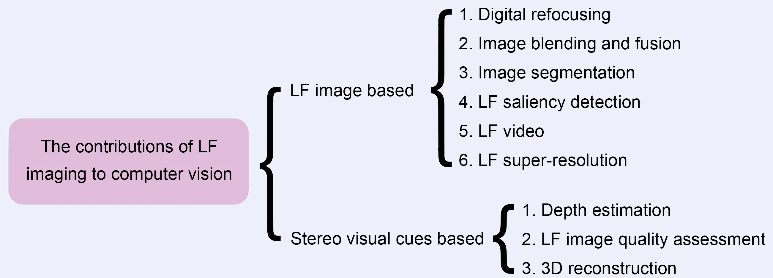
Fig.1 The contributions of light field(LF)imaging to computer vision
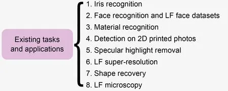
Fig.2 Eight existing tasks and applications
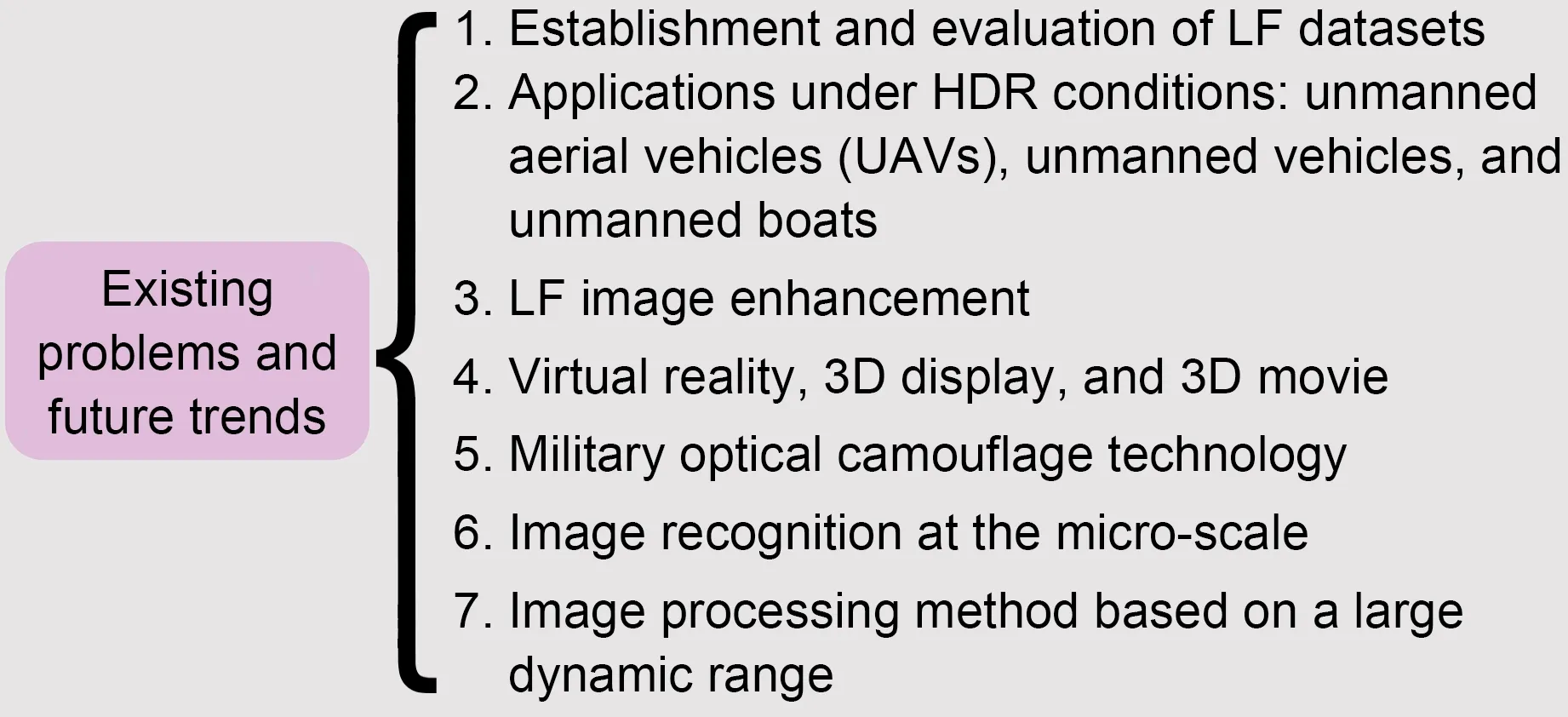
Fig.3 Seven existing problems and future trends
Studies of LF imaging in computer vision can be divided into four subject areas:(1) LF processing and image generation;(2)low-level vision;(3)middlelevel vision;(4) high-level vision.LF processing and image generation research includes mainly the LF function,optical schematic of LFC,and LF superresolution.Low-level vision research includes mainly LF depth estimation and 3D reconstruction.Middlelevel vision research includes mainly image segmen‐tation and blending.High-level vision research includes mainly face recognition and material recognition or detection.
3 Light field imaging technology
3.1 Light field function
For imaging convenience,traditional 2D imag‐ing systems ignore the analysis of the angle informa‐tion of the light rays.They directly analyze the direc‐tion information of the light rays on which the lens focuses,such as a pixel point(s,t)in a certain exposure time recorded on a charge-coupled device (CCD) or complementary metal-oxide-semiconductor (CMOS).For the basic principle model of LF imaging (Fig.4),the LF information is determined by recording the intersection points (u,v) and (s,t) information of each light ray intersecting the lens plane and image plane.Based on the above imaging principle,the four-dimensional(4D) LF information can be regarded as a summary of each light ray’s information.
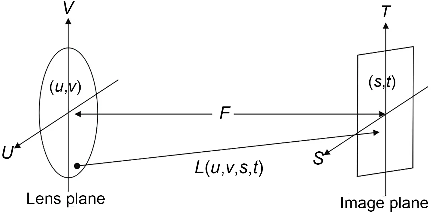
Fig.4 A conceptual diagram of light field imaging
In addition,the 4D LF can be expressed in a visual way.Thestplane is regarded as a group of cam‐eras that can obtain light,and theuvplane is regarded as the focal plane of the camera.Furthermore,the two-plane LF modelL(u,v,s,t) can demonstrate the acquisition of LF in two different ways.First,the camera captures all the light rays passing through thestplane and forming the focus with theuvplane (a set of rays at a certain viewpoint),and represents the 4D LF with a 2D array of images (Fig.5a).Each 2D image is called a subaperture image.Second,the number of samples on thestplane is positively related to the number of viewpoints,and the number of sam‐ples on theuvplane is positively related to the resolu‐tion of the camera.Therefore,in general,thesandtdimensions are referred to as the angular dimensions,and theuandvdimensions as the spatial dimensions.By acquiringIs*,t*(u,v) andIu*,v*(s,t),slicesEv*,t*(u,s)orEu*,s*(v,t)can be produced,also known as epipolar plane images(EPIs).
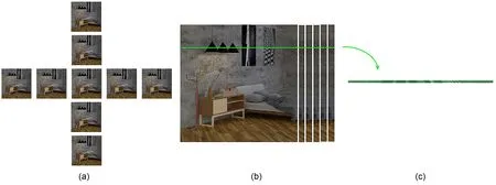
Fig.5 The 4D LF and EPI:(a)a subaperture image;(b)LF sub-view Iu*,v*(s,t);(c)EPI
When the camera (fixeds*t*plane) is kept sta‐tionary,subaperture imagesIs*,t*(u,v)can be collected.Similarly,when theu*v*plane is fixed,the LF subviewsIu*,v*(s,t)composed of light rays from different viewpoints can be collected.The EPI contains spatial information and angular information about an LF.At the same time,the points of different depths of an object are generally regarded as lines with different slopes in EPIs.The slope of a line represents the depth information of a point in the object,and thus the EPI is widely used in object depth estimation research.
3.2 Light field acquisition
In terms of structure,there are two main LF acquisition types:multi-camera array structure and single camera optical element structure.These two LF acquisition methods with different structures can effectively acquire LF scene information.
3.2.1 Multi-camera array structure
Multi-camera array structure means that multi‐ple cameras are placed at different viewing angles to capture an image of same object and obtain the LF information of different viewpoints.Levoy and Han‐rahan (1996) installed a camera on an LF gantry to acquire complete LF information,including the four degrees of freedom of 2D translation and 2D rota‐tion.Yang (2000) used an 8×11 lens array to conduct multi-perspective imaging of a target,and then used a flat plate scanner to complete a scan of the transver‐sal image plane to finish recording all of the LF infor‐mation.However,these two LF acquisition devices are suitable only for LF acquisition of static objects.To solve this problem,Zhang C and Chen(2004)pro‐posed a multi-camera array structure that can adjust the attitude independently.Each camera is fixed in a mobile structure unit,which can adjust indepen‐dently in the horizontal direction and a 2D rotation direction.Wilburn et al.(2005) proposed several cam‐era arrays with different configurations.By control‐ling the time accuracy and relative position accuracy of each camera,the LF can be processed accurately in time and space to obtain high-quality synthetic images (Fig.6).At the same time,many studies have proven that increasing the camera array improves the viewing angle range of the imaging system.In addition,synthetic aperture imaging technology has more freedom and flexibility in focus selection and depth of field adjustment.It is applicable to many visual tasks,including recognition and classification.
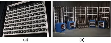
Fig.6 The different forms of camera arrays:(a) camera array with independent attitude adjustment;(b) Stanford camera array
3.2.2 Single camera optical element structure
The LF single camera optical element structure acquisition method refers to adding optical modulation elements to a single camera,and then changing the imaging structure to redistribute the four-bit LF in‐side the camera to a 2D plane.The optical path mod‐el of the first handheld LFC (Plenoptic 1.0) is shown in Fig.7.The imaging device places a microlens array at the focal plane of the traditional camera,and the image sensor is placed at one focal length from the microlens(Ng et al.,2005).Beams from dif‐ferent directions at the same point can be recorded by the image sensor through refraction of the main lens and focusing on the microlens array.The posi‐tion resolution of the LF recorded by the Plenoptic 1.0 camera is related to the number of microlenses.The angular resolution of the LF is equal to the pixel resolution of the LF.At the same time,the imaging performance shows that each subaperture image is consistent with the aperture shape of the main lens and the regularly arranged sub-images.
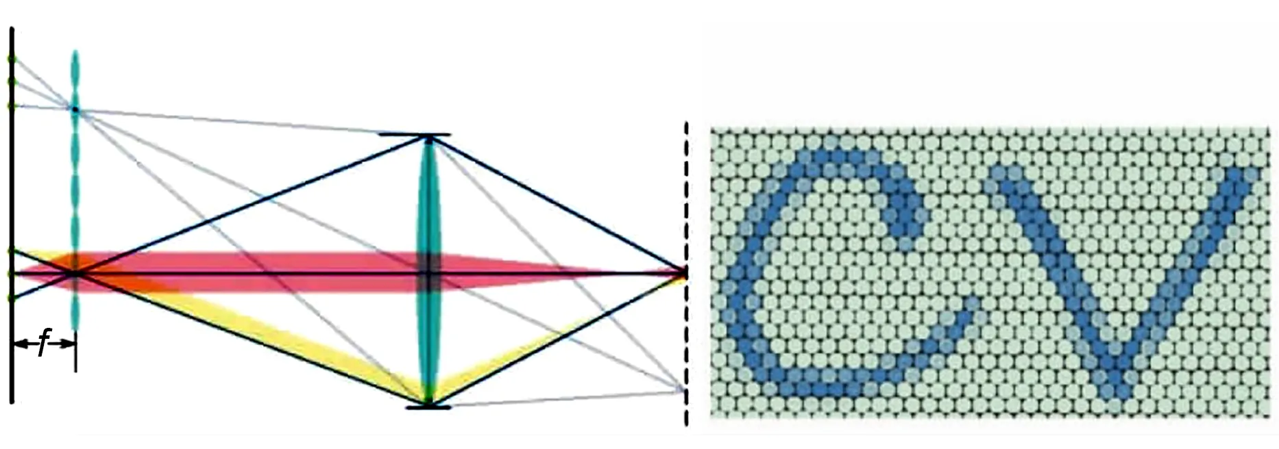
Fig.7 Optical path model of the first handheld light field camera(Plenoptic 1.0)
Lumsdaine and Georgiev (2009) proposed the Plenoptic 2.0 LFC.The optical path model of the camera is shown in Fig.8.The largest difference from Plenoptic 1.0 is that the camera places micro‐lens arrays before and after the focal plane position,and the image sensor is placed at a certain distance behind the microlens array for the image sensor to realize early focusing or secondary focusing.The pre-focused sub-image is a positive image,and the secondary focused image is an inverted image.Each sub-image represents the observation at the imaging of the main lens.In addition,because the angular resolution of the LF imaging model is directly related to the relative distance of the main lens,microlens array,and image sensor,there is a compromise between angular resolution and position resolution.
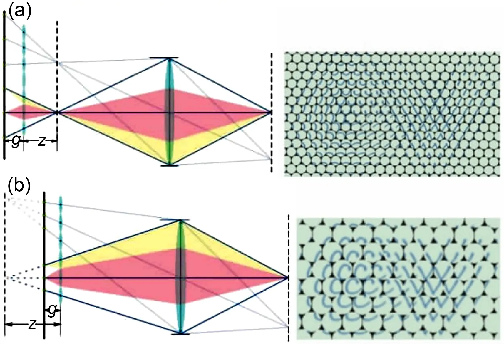
Fig.8 The optical path model of the Plenoptic 2.0 LFC:(a)secondary focusing;(b)focus in advance
Liang et al.(2008) proposed a programmable aperture camera.As shown in Fig.9,the camera sam‐ples the subaperture of the main lens through multiple exposures,and each exposure allows only the light at the specific subaperture position to be captured on the image sensor.For the selection of subapertures,a specific binary coding form is adopted.The LF col‐lected by the camera has the same spatial resolution as the image sensor.However,this is at the expense of long exposure time and a high image signal-to-noise ratio,and the amount of additional data accrued by multiple exposures is an additional burden.

Fig.9 The programmable aperture
3.3 Light field representation
The most widely used consumer LFC,the Lytro,is composed mainly of a main lens,a microlens array,and a photosensor.A microlens array is placed between the main lens and a photosensor (Fig.10) (Zhang J et al.,2020).This microlens array structure can divide the incident light rays in the main lens into many small parts in space.At the same time,each micro‐lens can carry out independent projection transforma‐tion,and each part is focused on the focal plane by the corresponding microlens to obtain the corre‐sponding microlens image.Finally,a series of micro‐lens images are represented as LF images.
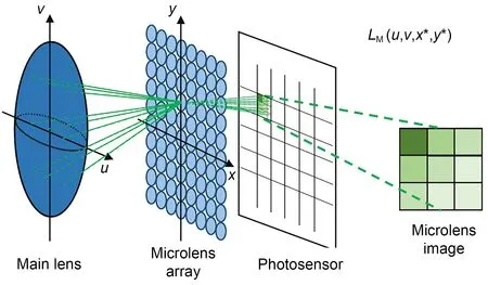
Fig.10 Optical schematic of an LFC containing a main lens,a microlens array,and a photosensor
As shown in Fig.11,the generation of all LF images results from the integration and summation of all light ray information recorded on the refocus plane:
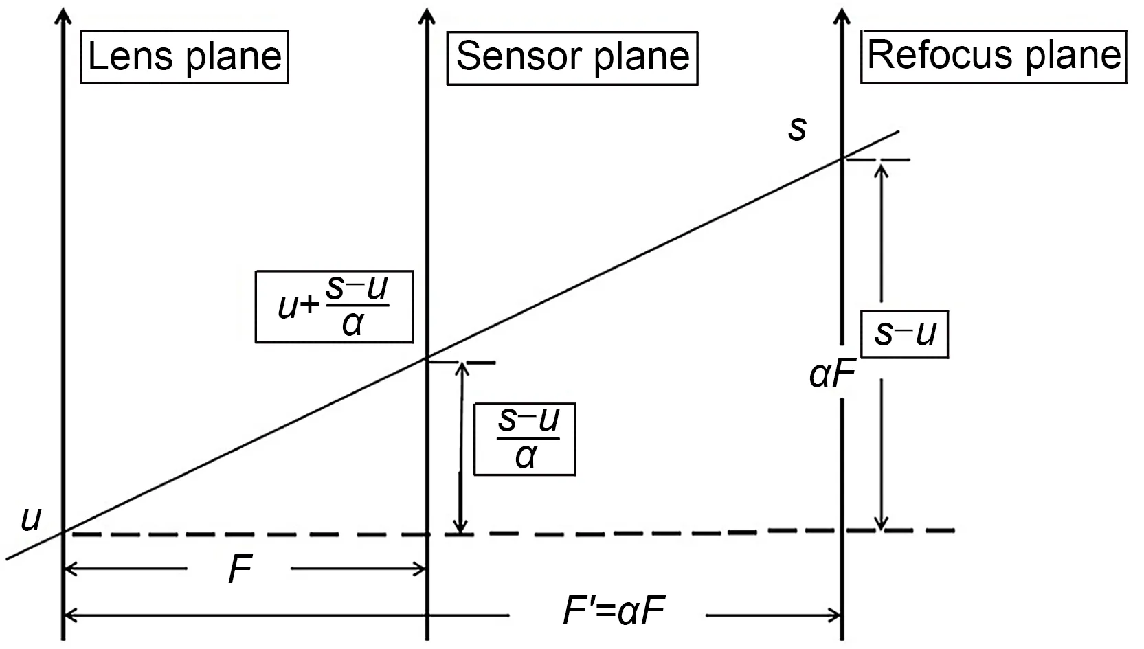
Fig.11 Schematic of LF refocusing

whereEF(s,t)represents the radiation intensity of pixel(s,t),LF(u,v,s,t)denotes the light ray information,andFrepresents the distance between the lens plane and the sensor plane.
It is assumed that the intersection of the ray propagating in a certain direction and the refocus plane is (s,t).Based on the geometric relationship,the intersection of the ray and the sensor plane is.Because the radiation energy remains unchanged during propagation under the same light,the following can be obtained:
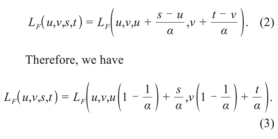
When Eq.(3)is introduced into Eq.(1),the sec‐tion image of the refocus plane can be obtained:
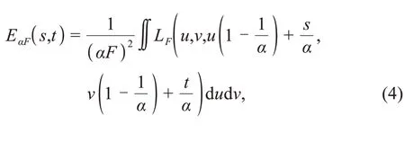
whereurepresents the lens plane,F′=αFindicates the distance between the lens plane and the refocus plane,andαrefers to the focusing coefficient for the distance between the lens plane and the refocus plane that needs to be adjusted.Different refocused images can be obtained by changing the focusing coefficient.
4 Light field imaging processing
4.1 Digital refocusing
Ng et al.(2005) proposed the first handheld LFC that can record the complete 4D LF information.They suggested that each focus image based on a microlens array is essentially a 2D slice representa‐tion of the acquired 4D LF information.Further‐more,they demonstrated digital refocusing and view‐point manipulation,coupled with custom software(Fig.12).The experimental examples included human portraits and high-speed action.In addition,Lumsdaine and Georgiev (2009) proposed a new expression of LF.They regarded the microlens array as a separate imaging system.The focal plane of the imaging sys‐tem was located on the main lens,and the final LF data had a higher spatial resolution.Georgiev and Lumsdaine (2010)proposed a real-time algorithm for synthesizing full screen refocused images from dif‐ferent viewpoints.Fiss et al.(2014) simplified the solution mode of the digital refocusing problem and directly projected the original information captured by the LFC to the focus output plane.Benefiting from the characteristics of LFCs with a large depth of field,Guo XQ et al.(2015) proposed a barcode image cap‐ture method that can refocus at different depths and demonstrated the technology in practical applications.

Fig.12 Reformed photographs:(a) refocused human portraits;(b)refocused high-speed action
4.2 Image blending and fusion
Image blending technology refers to the process of producing a seamless high-resolution image using multiple overlapping images.Traditional image blend‐ing technology includes the following three main parts:image pre-processing,image registration,and image fusion.Traditional 2D image blending technol‐ogy has been greatly developed,but most techniques are complex and have a blending parallax in the verti‐cal direction.
Afshari et al.(2012) introduced a new linear blending technique based on spherical LFC.The spher‐ical LFC was applied to provide multiangle infor‐mation for different focal planes to improve the effec‐tiveness of visual reconstruction.Due to the limita‐tion of sensor resolution,the LFC often performs sparse sampling in the spatial or angular domain.Kalantari et al.(2016) introduced a novel convolu‐tional neural network (CNN) based framework to synthesize new views from a sparse set of input views.Raghavendra et al.(2013b) proposed a new weighted image fusion framework,which can adaptively assign a higher weight to the better-focused image to ensure the image fusion effect.Wang YQ et al.(2018)consid‐ered that the traditional fusion algorithm would cause color distortion when fusing multifocus images with a small depth of field.Therefore,they applied the wave‐let transform method to multifocus image fusion,effectively ensuring visual performance.Nian and Jung(2019)introduced a machine learning based multi‑focus image fusion scheme using LF data (Fig.13).First,they used CNNs to extract the features of each multi-focus image.Second,they trained the network parameters of the multi-focus images together to ensure consistency of features.Then,they put the fea‐tures to the second CNN to obtain an initial focus map.Finally,they performed morphological operations of opening and closing to process the initial focus map and then obtained the focus map.Based on the pro‐cessed focus map,a full clear image was generated.

Fig.13 Machine learning based multi-focus image fusion
4.3 Image segmentation
Image segmentation divides the image into sev‐eral regions according to features such as grey,color,spatial texture,and geometry.These features show consistency or similarity in the same region,but obvi‐ous differences between regions.Unlike traditional multiple view segmentation methods,the use of LF images helps improve the accuracy of segmentation due to the richness of data and the high correlation between multiple views(Wu et al.,2017).
Berent and Dragotti (2007) proposed an EPIbased energy minimization method for the occlusion segmentation problem.Similarly,Sheng et al.(2016)modified the structure tensor on the EPIs to compute the disparity,and presented a remarkable segmenta‐tion model based on superpixel segmentation,as well as a graph-cut algorithm.Using the graph-cut theory and Markov random field(MRF)framework,and ana‐lyzing multiple views,Campbell et al.(2010,2011)proposed two automatic segmentation algorithms in the voxel space and image space.Hog et al.(2016)introduced a new graph representation for interactive LF segmentation using MRF.The proposed method exploited the redundancy in the ray space,decreasing the running time for the MRF process.Moreover,for multilabel segmentation,Wanner et al.(2013b) pro‐posed a variable framework based on analyzing the ray space of 4D LFs.They also proved that LF data can not only be trained,but also provide available data for labelling.Based on the analysis of depth informa‐tion and the redundancy contained in LF data,Mihara et al.(2016) proposed a supervised 4D LF segmenta‐tion method.Considering that the rays are the basic unit of each pixel,Zhu et al.(2017) presented a light field superpixel (LFSP) method,which can effective‐ly solve the ambiguity of the segmentation boundary.Yücer et al.(2016) used densely sampled images from different angles as input,and presented an avail‐able automatic segmentation method for 2D and 3D space.The depth information contained in the LF focus region is easily accessible and is helpful for segmentation.Gao et al.(2017) introduced pulse coupled neural networks (PCNNs) for precise and straightforward segmentation.Furthermore,to address the background sensitivity problem in foreground segmentation,Chen et al.(2015) presented an auto‐matic foreground segmentation algorithm relying on LF all-in-focus images.Lee and Park (2017) intro‐duced an approach separating the foreground and background using gradient information directly at the pixel level,which can be effectively applied to the processing of occlusion problems.To address the pro‑blem of inaccurate segmentation of transparent objects,Johannsen et al.(2015) presented a method apply‐ing disparity and luminance information from LF data to solve the problem of reflective or transparent surface segmentation.Xu et al.(2015)proposed a seg‐mentation framework for transparent objects,named TransCut.This method uses the LF-linearity and occlu‐sion detector rather than color and texture informa‐tion to describe transparent objects.Moreover,Xu et al.(2019) updated the LF-linearity algorithm and proposed a new dataset for evaluation to obtain better results.The new algorithm is automatic,requiring no human interaction.Lv et al.(2021) introduced LFSP technology,which improved the accuracy of occlu‐sion boundary area segmentation.
4.4 Light field saliency detection
The main purpose of saliency detection is to detect the most interesting objects in an area.How‐ever,in the face of complex scenes such as those with similar background color and depth,the existing detection algorithms for 2D images cannot achieve accurate detection results.
Li NY et al.(2014) first attempted to use LFs as input for the saliency detection problem and devel‐oped the first saliency detection algorithm for LFs.The algorithm substantially improves the performance of saliency detection in complex scenes by calcu‐lating the image space and the structural similarity between focal stack images,as well as using the prior candidate knowledge of foreground and background.Furthermore,they used the Lytro LFC to construct a light field saliency dataset(LFSD),including the origi‐nal 4D data and ground truth.The scenes in this dataset were divided into indoor and outdoor parts.More‐over,Li NY et al.(2015)processed LF depth informa‐tion and focus information as one-dimensional visual features,proposing a single saliency detection frame‐work with strong robustness in multi-dimensional data.Zhang J et al.(2015) proposed a novel saliency detection model based on analyzing all LF cues to improve their accuracy,and this proved to be benefi‐cial for 2D and 3D saliency detection.Taking the accuracy of saliency detection as an evaluation index,Zhang XD et al.(2015)compared LF and 2D saliency detection.Experimental results showed that LF sa‐liency detection outperformed 2D saliency detection in complex occlusions and background clutter.Wang AZ et al.(2017) fused the useful visual cues con‐tained in LF data and proposed an improved Bayesian integration framework for saliency detection.Zhang J et al.(2017) proposed an LF multiple cues based saliency detection framework,with cues including color and depth.Meanwhile,they established a real data LF dataset,Hefei University of Technologylight field saliency detection (HFUT-LFSD).Zhang M et al.(2019) exploited LF combined with long short term memory(LSTM)and constructed the largest LF dataset,Dalian University of Technology-light field saliency detection (DUT-LFSD).Piao et al.(2019a)fully exploited the correlation of the information inher‐ent in LF data and proposed a saliency detection frame‐work based on depth-induced cellular automata(DCA).The framework can effectively solve the main prob‐lems of missed and false detection under complex background conditions.The main flow of the frame‐work is shown in Fig.14.First,the focal stack,depth map,and all-in-focus images are used as the overall input of the framework.Second,the focal stack and depth map are used to guide and obtain object-guided depth and background seeds.Meanwhile,all-in-focus images and object-guided depths are guided for seg‐mentation.Third,the depth-induced saliency is ob‐tained by multiplying the object-guided depth and the contrast saliency.At the same time,a DCA model is used to optimize the parameters,and optimized saliency results are obtained.Finally,the Bayesian framework is used to fuse depth-induced saliency and optimized saliency while conditional random field(CRF) is used to obtain the final saliency map.To explore the contribution of each focal slice to saliency detection,Piao et al.(2021) proposed a patch aware network (PANet) with a multisource learning module and achieved optimal results at the same time.
Although some LF saliency detection datasets have been established,most have limitations.There‐fore,deep learning methods based on big data cannot perform well;thus,the advantage of the rich LF image information cannot be demonstrated.To solve this problem,Wang TT et al.(2019) introduced a largescale dataset for 4D LF saliency detection.The data‐set consisted of 1465 all-in-focus images.Each image had a well-labelled ground truth and focal stacks.In addition,they introduced a fusion framework based on an attentive recurrent CNN,which improves the performance for 4D LF saliency detection.Further‐more,Piao et al.(2019b) used the Lytro LFC to con‐struct a new 4D LF dataset for saliency detection with 1580 LF images.Each LF image consisted of multi‐ple views and a pixelwise ground truth of the cen‐tral view.Moreover,they presented an available end-to-end CNN scheme based on LF synthesis and LF-driven saliency detection to ensure the improve‐ment in the final experimental results.In addition,Zhang J et al.(2020) first proposed to analyze the angular features with a CNN from an LF image for saliency detection.Finally,to compare the perfor‐mance of the algorithms comprehensively using three datasets,we adopted four popular metrics,including theSα-measure,Es-measure,Fβ-measure,and mean absolute error (MAE).The results of quantitative comparisons are shown in Table 1.

Table 1 Quantitative comparisons of the Es-measure,Sα-measure,Fβ-measure,and MAE score on the 4D LF dataset
TheSα-measure can evaluate the region-aware and object-aware structural similarity between the saliency map and ground truth.The definition ofSαis given as

whereSois the final object-aware structural similarity measure,Sris the final region-aware structural simi‐larity measure,α∈[0,1]is a balance factor betweenSoandSr,Gis the ground truth map,andSpis the pre‐diction map.
TheEs-measure can capture local pixel match‐ing information and image-level statistics.The defi‐nition ofEsis given as

wherewandhare the width and height ofGrespec‐tively,symbolsis the enhanced alignment matrix,and(x,y)are the coordinates of each pixel.
TheFβ-measure is the harmonic mean of the average precision and average recall.It is defined as

whereβis a parameter to achieve a trade-off between recall and precision.
The MAE is the average difference betweenSpandG.The definition of MAE is given as

4.5 Light field video
Traditional 2D video equipment cannot express a scene’s real stereo effect because of the limitations of imaging sensors.LF imaging technology can pro‐vide complete LF video information,including the required six degrees of freedom for natural scenes.
In early research,Wilburn et al.(2002) pro‐posed a flexible and modular LF video camera.This LF video camera is composed mainly of more than 100 controllable 2D cameras,and visual control is real‐ized mainly by one computer at the same time.To solve the problem of a shaky output video of a handheld LF video camera,Smith et al.(2009)used the space‑time optimization method to optimize the objects while enabling the important image features in the input video to move smoothly in the output video.Mean‐while,they used LF video to provide the characteris‐tics of multiple views and proposed an LF video optimization method without path reconstruction.Furthermore,to improve LF data capture,processing,and display,Balogh and Kovács (2010) proposed an end-to-end LF video rendering processing software.The software includes multiple cameras,a highperformance personal computer,and a high-speed network.The LF rendering video processed by this system is real-time,and has a high frame number and high resolution.In particular,Tambe et al.(2013)broke the trade-off between spatial resolution and an‐gular resolution due to the prior knowledge of LFCs,and introduced an LF video camera for dynamic highresolution LF video reconstruction using redundant scene information.Furthermore,Sabater et al.(2017)proposed a real-time,accurate pipeline for LF video capture and processing,including depth estimation algorithms and color homogenisation algorithms.
Wang TC et al.(2017) proposed a hybrid imag‐ing system using a Lytro camera and a digital video camera.A digital camera was used to capture the temporal information,solving the problem of miss‐ing a large amount of information between adjacent frames.The Lytro camera was first combined with a 30-frame/s digital video camera (Fig.15a).The inputs in the system included a standard 2D video and a 3-frame/s LF sequence (Fig.15b).Finally,combining the angular information and temporal information ob‐tained from the 3-frame/s LF sequence and 30-frame/s 2D video,a complete LF video with all angular views could be obtained (Fig.15c,left).This system imple‐ments digital focus and parallax generation during video playback.Mehajabin et al.(2020) proposed a novel pseudo-sequence-based coding order,which efficiently improves compression for LF videos.

Fig.15 The LF video hybrid imaging system:(a)system setup;(b)system input;(c)system output
4.6 Light field super-resolution
As a piece of new imaging equipment,the LFC has a trade-off between spatial resolution and angular resolution.The image resolution generated by the LFC is low,restricting the application of LF imaging technology (Cheng et al.,2019).Recently,to solve this problem,many super-resolution methods have been proposed,including three main categories:LF data structure based methods,learning-based meth‐ods,and multisensor-based methods (see supplemen‐tary materials,Sections 1.1.1,1.1.2,and 1.1.3).
4.7 Depth estimation
The rich 4D LF data make LF depth estimation research possible.The LFC is a single-sensor imag‐ing device.Data acquisition is not affected by other sensors operating in cooperation,which gives it sta‐bility and convenience.In our summary,we divided the methods of LF depth estimation into two catego‐ries:data-based methods and learning-based methods.The data-based methods can be divided further into two parts:EPI-based methods and LF-image-based methods.LF-image-based methods include the mea‐surement analysis of the subaperture image and the refocus image.Furthermore,they include some pro‐cessing methods based on LF data for some unique problems,such as occlusion and scattering medium(see supplementary materials,Sections 1.2.1 and 1.2.2).
4.8 Light field image quality assessment
Many LF image processing methods and appli‐cations have been proposed.LF images inevitably struggle with various wide distortions,leading to a reduction in image quality.Therefore,the quality assessment of LF images is critical,and can better guide the collection,processing,and application of LF images.In recent decades,various image quality assessment (IQA) algorithm models have been pro‐posed,but these are used mostly to evaluate natural images and screen images.Because different image types have different characteristics,they are not suit‐able for direct assessment of LF images.Therefore,accurately evaluating LF image quality and efficiency according to visual characteristics becomes an urgent need.
Fang et al.(2018) presented a full reference LF image quality assessment (FRLFIQA) algorithm.This method predicts the LF image quality by measuring the gradient similarity between the EPI of the original LF image and the EPI of the distorted image.Huang et al.(2018) proposed another FRLFIQA algorithm.This algorithm estimates the LF image quality by fit‐ting the distribution of the average difference between each perspective of the original image and the dis‐torted image.Furthermore,Tian et al.(2021) pro‐posed a symmetry and depth feature based model for LFIQA.The main idea was to use symmetry and depth features to fully search the color and geometric information.In addition,Paudyal et al.(2019) pro‐posed a reduced-reference LFIQA(RR LFIQA)algo‐rithm.This algorithm is based on the correlation between the depth image quality of the LF image and the overall quality of the LF image.It measures the structural similarity between the depth image of the original image and that of the distorted image to pre‐dict the overall quality of the LF image.Further‐more,considering that existing LF image quality evaluation is closely related to the reliability and cor‐relation of LF datasets,Paudyal et al.(2017) built an LF image quality dataset composed mainly of the original data,compressed images,and annotation information.Shi et al.(2018)built an LF image data‐set containing five degrees of freedom that can pro‐vide depth cues and the most realistic LF display.At the same time,they used the dataset as experimental samples to verify the effect of the inherent LF proper‐ties on the quality of the LF image.
The methods by Fang et al.(2018),Huang et al.(2018),Tian et al.(2021),and Paudyal et al.(2019)need to use the original image information,which requires additional bits to transmit the information of the original LF image.Therefore,in the past two years,no-reference LF quality evaluation methods that fully consider the influence factors of LF image quality have been widely studied.Based on tensor theory,Shi et al.(2019)explored the LF 4D structure characteristics and proposed the first blind quality evaluator of the LF image.Considering the influence of angle consistency,chrominance,and luminance on LF image quality,Zhou W et al.(2020) proposed a novel LF image quality evaluation model,called the tensor-oriented no-reference LF image quality evalu‐ator.To reduce the impact of LF image quality degra‐dation,Shi et al.(2020) measured EPI in the form of local binary pattern (LBP) features to obtain angular consistency features,which were used as the basis to address the problem of LF image quality degradation.Shan et al.(2019) constructed an LF image quality assignment dataset with a total of 240 samples by combining 4D decoding technology and human sub‐jective feelings.At the same time,they used a sup‐port vector regression (SVR) model to represent the 2D and 3D characteristics of the LF image and pro‐posed a no-reference IQA metric.Meng et al.(2019)proposed an accurate,time-efficient LFIQA frame‐work based on the fact that the degree of distortion of LF refocusing images can accurately reflect the whole LF image quality.Cui et al.(2021) proposed a macro-pixel differential operation method based on spatial-angular characteristics to quantify the LF image quality.
4.9 Three-dimensional reconstruction
LF information containing multiple data types has great potential in 3D reconstruction.Levoy et al.(2006) applied the theory of LF rendering to micro‐scopic imaging and developed an LF microscope(LFM),which can obtain object images of different depths in an exposure and carry out 3D reconstruc‐tion of the object.Broxton et al.(2013) proposed a 3D deconvolution method for 3D reconstruction by decoding dense spatial-angular sampling.At the same time,they demonstrated by experiment the highresolution characteristics of this method for object reconstruction.Murgia et al.(2015)proposed a novel algorithm that can reconstruct a 3D point cloud from a single LF image through a sequential combination of image fusion,feature extraction,and other technol‐ogies.Sun et al.(2017) fully optimized the calibration of focused LFCs based on the Levenberg-Marquardt algorithm and proposed a 3D reconstruction method for flame temperature based on the least-square QRfactorization algorithm.Marquez et al.(2020) pro‐posed a tensor-based LF reconstruction algorithm,which shows better performance and lower computa‐tional complexity than matrix-based methods.Through the fusion of LF data and regression prediction,Cui et al.(2021) proposed a 3D reconstruction algorithm for bubble flow.
5 Tasks and applications
5.1 Iris recognition
Iris features are widely used in biometrics because of their uniqueness and non-replicability.However,most iris image collectors are affected by the limita‐tion of a small depth of field,which leads to poor quality of the collected iris images,and inevitably affects recognition.
Recently,to address the above problems,the use of LFCs was explored for iris recognition.Zhang C et al.(2013) presented a new iris sensor based on LF photography and constructed the first LF iris image database using the sensor.Raghavendra et al.(2013a)leveraged the LFC and provided useful infor‐mation in terms of multiple depths (Fig.16).They collected a new iris and periocular biometric dataset,and then proposed a new scheme for iris and periocu‐lar recognition based on the LBP feature extraction algorithm and the sparse reconstruction classifier.In addition,to prevent spoof attacks on the biometric system,Raghavendra and Busch (2014) presented a novel way of addressing spoof detection by fully exploiting the depth and focus information of the LFC for visible spectrum iris biometric systems.Fur‐thermore,because LFCs can hold additional informa‐tion that is quite useful for biometric applications,Raghavendra et al.(2016) carried out an empirical study for iris recognition using an LFC.They first collected a new iris dataset in an unconstrained envi‐ronment by simulating a real-life scenario,and then explored the supplementary information available from different depth images.These were rendered by the LFC by either choosing the best focus from multi‐ple depth images,or exploiting the supplementary information by combining all of the depth images using super-resolution.Finally,iris recognition results with more than 90% reliability were reported from an extensive set of experiments.

Fig.16 The iris and periocular recognition scheme of Raghavendra et al.(2013a)
5.2 Face recognition,detection,and a light field face dataset
As the most extensive biometric scheme,face recognition is vulnerable to biological attacks(Sepas-Moghaddam et al.,2018).There are two types of LFbased methods for face recognition:texture-based methods and focus and depth based methods (see supplementary materials,Sections 2.1.1 and 2.1.2).
5.3 Material recognition
Although there have been few studies of mate‐rial recognition based on LF data,the approach has provided a wide range of ideas for related research.The direct measurement method has been widely used in traditional image material recognition research.The principle is to analyze multiple views of a point simul‐taneously.Wang TC et al.(2016a) proposed a 4D LF material recognition system to prove whether the mul‐tiple views obtained in LF data have a better effect than traditional 2D images in material recognition(Fig.17).First,they used a Lytro LFC to collect a ma‐terial recognition dataset containing 1200 images in 12 categories.Second,the images in the dataset were used as experimental samples to extract information from a total of 30 000 patches.Furthermore,this patch information was input to a specially designed CNN that can take the form of an LF as input and train the LF information to obtain a patch model.Finally,the patch model was fine-tuned in the full scene to obtain the fully convolutional network(FCN)model,and postprocessing was carried out to obtain the final recogni‐tion results.Guo et al.(2020)proposed corresponden‑ces in the angular domain to achieve the decoupling of spatial-angular features for LF material recognition.
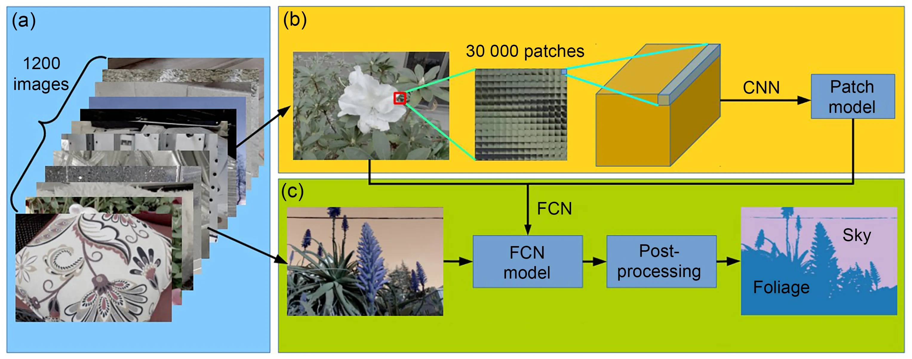
Fig.17 The material recognition system based on 4D LF information:(a)light field dataset;(b)CNN training procedure for 4D light fields;(c)full scene material recognition
5.4 Detection on 2D printed photos
Many biological detection methods are based on conventional 2D imaging devices,and are at the mercy of imaging principles.Traditional 2D cameras will lose stereo information during scene information acquisition,thereby leading to a large number of 2D printed photos attacking the authentication program.The most substantial differences between the printed photo and the original scene photo are the gradients of epipolar lines and depth information.Compared with the original scene photo,the gradients of the epipolar lines of the printed photo remain unchanged,and the printed photo does not contain depth information.
Based on this,Ghasemi and Vetterli (2014)extracted an energy feature vector from epipolar lines,and then distinguished the printed photo from the original photo by distinguishing the feature vec‐tor.Similarly,through the analysis of viewpoint and light information of the subadjacent aperture image,Kim et al.(2013) proposed a spoof attack detection algorithm based on LBP and support vector machine(SVM).This algorithm not only can detect printed photos correctly,but also has good robustness for the detection of gradient objects.Considering that the system of pedestrian detection is easy to disturb by many 2D printed fake photos,Jia et al.(2018) con‐structed an LF pedestrian dataset including more than 1000 images.They proposed a 2D fake pedes‐trian detection framework based on LF imaging tech‐nology and an efficient SVM classifier.In addi‐tion,by analyzing the variation in the focus of depth images generated by LFC,Raghavendra et al.(2016)proposed a parallel spoof attack detection frame‐work (Fig.18).First,parallel face detection and preprocessing operations were carried out for the acquired images of different depths.The pre-processing opera‐tion was designed mainly to filter out image noise interference.Second,the focus measure operators were obtained by applying different focusing mea‐surement methods.Third,the relative and absolute values of focus transformations were estimated.Fi‐nally,the SVM classification method was used to dis‐tinguish the relative value and absolute value.

Fig.18 A 2D printed face detection framework based on different focus images
5.5 Specular highlight removal
The removal of specular highlights from an image can effectively ensure image quality.In recent years,LFCs have been widely used to remove specular highlights.
Through the decomposition of the EPI in LF,Criminisi et al.(2005) found that EPI has a high reg‐ularity.Therefore,they proposed an EPI framework based on math characteristics for specular highlight removal.Tao et al.(2015a)took advantage of this abi‑lity to later modify the focus point in LF data,and proposed an iterative method for specular highlight removal.Furthermore,they first proposed an algo‐rithm to determine the light source color by analyz‐ing the angle pixels in LF data.Meanwhile,the spec‐ular highlight can be removed by analyzing the light source color.Wang HQ et al.(2016)proposed a com‐bined specular highlight removal algorithm based on depth estimation and specularity detection.First,the depth map corresponding to the LF image with specularity was obtained by analyzing 4D EPI data.Then,each pixel of the image was classified as a saturated or unsaturated pixel using the thresholdbased specularity detection method.Then thek-means algorithm was used for pixel clustering,and the depth map obtained before was used for refocusing and filtering unsaturated pixels.Finally,the local color refinement method was used to complete the color correction of some saturated pixels.In addition,based on the analysis of 4D LF data,Alperovich and Gold‐luecke (2017) proposed a variational model based on a review of additional data available in LF.The pro‐posed model can remove specular highlights by sepa‐rating the shadow and the albedo in the LF.Recent works (Gryaditskaya et al.,2016;Sulc et al.,2016)also analyzed the LF data structure or later edited the composition to better complete specular high‐light removal.
5.6 Shape recovery
Effective and accurate acquisition of multiangle images of objects in a scene is the key to shape recov‐ery.Completing an accurate shape recovery of crys‐tals,ceramics,and other objects with glossy surfaces is difficult.In recent years,LF imaging technology has been widely used in shape recovery.
Tao et al.(2015a) presented a new photo consis‐tency metric,line-consistency,for shape recovery,revealing how viewpoint changes affect specular points.Furthermore,they made full use of the defo‐cus,correspondence cues,and shading in LF data.They used defocus and correspondence cues for local shape recovery and shading to further determine the depth of the object and improve the accuracy of the final shape recovery.Wang TC et al.(2016b)proposed a bidirectional reflectance distribution function(BRDF)invariant theory and invariant equation suitable for LF data analysis,which can effectively complete the shape recovery of different objects.The experimental results for the methods report the excellent effect on shape recovery.However,Li ZQ et al.(2017) found that Tao et al.(2015a) failed to consider that texture gradient information may play a complementary role in shape restoration,and may distort the shape recov‐ery of objects for non-Lambertian surfaces.They pro‐posed a general energy minimization formulation with autobalance ability,which can effectively recover the shape of complex BRDFs using only one LF image.Experimental results from a large number of studies show that this formulation is more accurate and ro‐bust than BRDF invariant reconstruction methods.In addition,Zhou MY et al.(2020) proposed a fixedstructure concentric multispectra LF(CMSLF)acqui‐sition system.In this system,each concentric circle has a fixed number of cameras to acquire the information of multiple views.The proposed system was highly effective for shape recovery under non-Lambertian conditions based on the dichromatic Phong reflectance model.A comparison of the experimental results with state-of-the-art methods is shown in Fig.19.
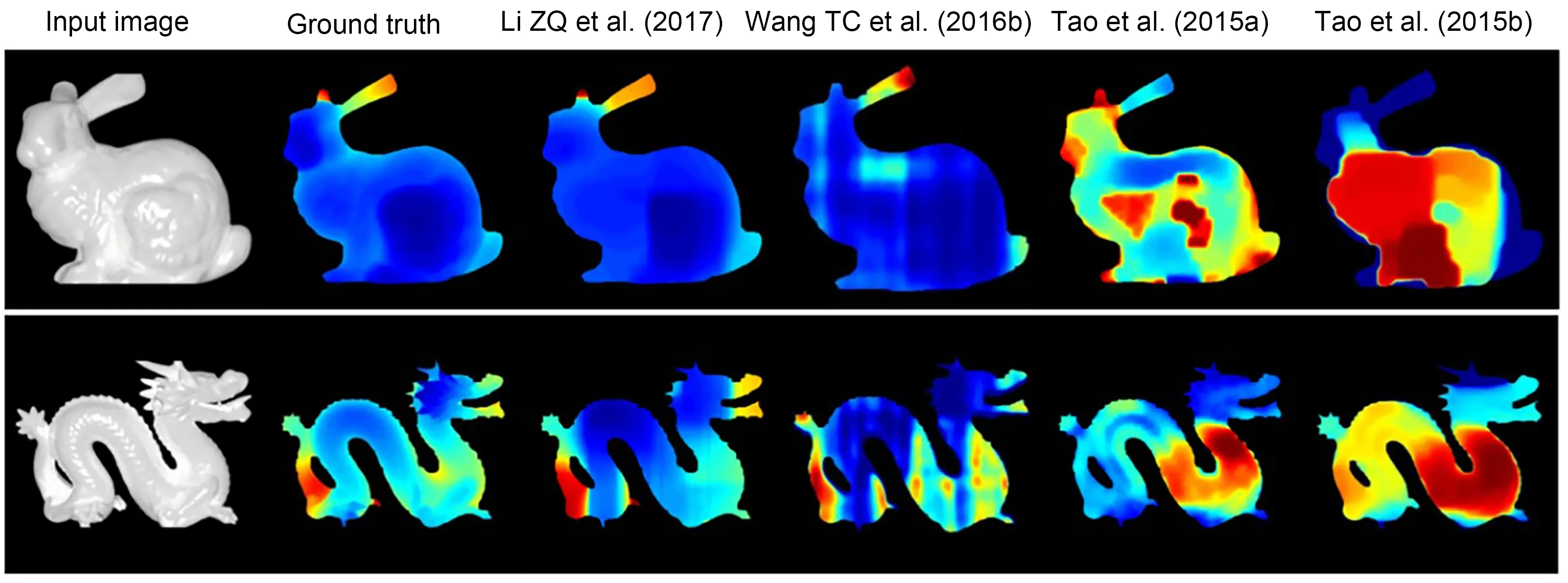
Fig.19 Comparison of the experimental results from state-of-the-art methods
5.7 Light field microscopy
LF microscopy (LFM) is a new 4D LF imaging technology that uses microlenses to achieve a bal‐ance between spatial resolution and angular resolu‐tion.The application of this technology can make weakly scattering medium or fluorescence specimens achieve the effect of high-speed imaging without scanning.Levoy et al.(2006) demonstrated a proto‐type LFM (Fig.20),composed of a high resolution Nikon 2D camera and a custom microlens array.The camera was placed atG,and the microlens array atF.Each microlens array recorded the relevant,focused image.They analyzed the optical performance of this method and showed its advantages for capturing the 3D structure of micro-objects.
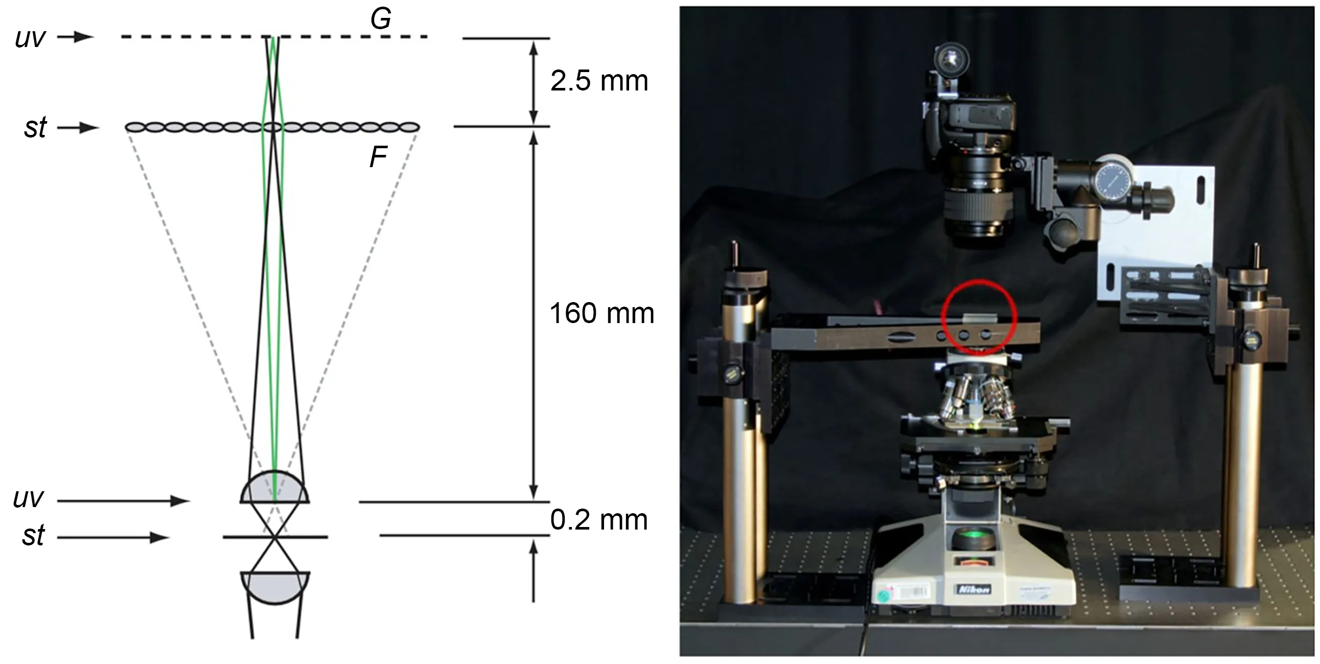
Fig.20 The first prototype light field microscopy
In addition,an optical model for LFM and a 3D deconvolution method for LFM were proposed by Broxton et al.(2013).Experimental results showed that this model could help obtain a higher spatial res‐olution with better optical sectioning in reconstructing volumes.However,the spatial resolution reconstructed by the LFM was nonuniform in depth information.The resolution at most imaging centers was low,while the resolution at thezplane was high.Wavefront cod‐ing techniques were applied by Cohen et al.(2014)to address this nonuniform resolution limitation by including phase masks in the optical path of the mi‐croscope.The performance of the LFM was improved.Furthermore,to complete the observation of in vivo specimens,a new 3D LFM with a high spatial resolu‐tion was proposed by Zhang M et al.(2017) by add‐ing a microlens array and relevant focusing optical elements to a traditional microscope.The experimen‐tal results showed that the 3D LFM can acquire seven subaperture images from different perspectives.To further expand the working range of the LFM,Hsieh et al.(2018)proposed a system based on a multifocal high-resistance liquid crystal microlens,which has advantages such as short response time and low driv‐ing voltage.Vizcaíno et al.(2021)applied fully CNN architecture to reconstruct configurable microscopic stacks from single LF images,which improved the time efficiency and reconstruction accuracy.
6 Existing problems and future trends
Although LF imaging technology has been widely studied and applied in computer vision,specific research is still lacking.In combination with current trending topics,we believe that researchers should make efforts in the following areas.
1.Establishment and evaluation of the LF dataset
LF dataset construction is essential for the appli‐cation of LF imaging technology to computer vision tasks.Kim et al.(2013)constructed an LF dataset for scene reconstruction from a high spatial-angular reso‐lution.Wanner et al.(2013a)constructed an LF bench‐mark dataset by densely sampling 4D LF data,Hei‐delberg Collaboratory for image processing1 (HCI1).Li NY et al.(2014) created an LFSD.Raghavendra et al.(2016) constructed an LF dataset for face and iris recognition.Tao et al.(2015a)built an LF dataset for depth estimation.Wang TC et al.(2015,2016a)con‐structed an LF dataset for material recognition and depth estimation under occlusion.Other kinds of LF datasets have been proposed by Paudyal et al.(2016) and Rerabek and Ebrahimi (2016),but there was a notable lack of large LF datasets for computer vision in previous studies.The datasets of Kim et al.(2013),Tao et al.(2015a),and Wang TC et al.(2015)each had fewer than 10 images.Moreover,part of the LF dataset was not representative and proved only the rationality.Therefore,the establishment of rich data and a wide range of LF datasets is a priority for future research.
2.Applications under high dynamic range (HDR)conditions:unmanned aerial vehicles(UAVs),unman‑ned vehicles,unmanned boats
The key to the application of UAVs,unmanned vehicles,and unmanned boats is that the imaging equipment must accurately obtain the scene informa‐tion under highly dynamic conditions for summary analysis.When LFC is applied,it can accurately obtain the complete 4D LF information of the scene under conditions of high-speed movement.Simulta‐neously,through the analysis and processing of 4D LF information by software,clear images of different focal planes can be obtained.However,because of the high dimensionality of 4D LF and technical limi‐tations,the 4D LF information collected by LFC can‐not be analyzed in real time,and the imaging effect is considerably reduced in HDR conditions.The HDR conditions refer to areas with high brightness under strong light sources (e.g.,sunlight,lamps,or reflec‐tion) and areas with low brightness such as shadows and backlight.Therefore,leveraging LFC imaging,solving the real-time problems of software and hard‐ware,and limiting the use of LFC under complex conditions are the key issues.
3.Light field image enhancement
LFC will be polluted by various kinds of noise in image acquisition,transmission,and storage,which will affect the quality of the LF image.Reducing the influence of noise in the acquisition of LF images and enhancing the known LF image to improve the visual expression effect are important aims for future research.
4.Virtual reality,3D displays,and 3D movies
Accurate and efficient data acquisition in dynamic environments is the core content of virtual reality,3D displays,and 3D movies.However,the LFC has poor applicability in harsh conditions,such as over‐exposure,dim light,or occlusion.Widely used LFCs,such as the consumer-Lytro or industrial-Raytrix,which cannot meet the shooting effect higher than 30 frames/s,limit the development of 3D computer vision tasks.Therefore,the development of strategies to compensate for the shortcomings of LFCs while making full use of 4D LF information is a future trend.
5.Military optical camouflage technology
In military optical camouflage research,the goal is to reduce the optical differences between the target and the surrounding background as much as possible,making it difficult for reconnaissance instruments to detect and distinguish.Therefore,the analysis and application of 4D LF information to improve military optical camouflage technology is a future trend.
6.Image recognition at the micro-scale
LFC can obtain the complete 4D LF informa‐tion of an object at the expense of losing part of the spatial resolution,restricting the development of image recognition at the micro-scale.Ensuring the integrity of 4D information acquisition without losing the image resolution at the micro-scale is still an urgent problem to resolve.
7.Image processing method based on HDR
Because the luminance contrast of the real visual environment is far beyond the limits of the dynamic range of image sensors,the performance of LFCs is weak when there is a limited dynamic range,such as with overexposure,strong light,or dim light.There‐fore,using LFC to capture 4D LF information with an HDR condition is an urgent problem.
8.Optimal relationship between spatial resolu‐tion and 4D light field information acquisition
The image acquired by an LFC usually has a low spatial resolution.If the spatial image resolution is improved considering the axial resolution,higher requirements are needed for the performance of the photodetection device.Obtaining complete 4D LF information without losing spatial image resolution is one of the most vital aims of LF imaging research.In addition,increased storage capacity and processor speed are required because a huge amount of data will be obtained in one exposure.Based on the above anal‐ysis,the application of LF imaging technology in com‐puter vision research still needs to resolve the follow‐ing issues:the specific implementation,the balance be‐tween the software process ability and hardware shoot‐ing effect,commercialization costs,and convenience.
7 Conclusions
Light field imaging technology aims to establish the relationship among light information in spatial domain,visual angle,spectrum and time domain,and realize coupling sensing,decoupling reconstruction,and intelligent processing.
In this paper,we have summarized the impor‐tance of light field imaging technology for computer vision tasks and listed representative contributions from all interested researchers.The representative stud‐ies were focused mainly on depth estimation,image segmentation,saliency detection on light field,light field image quality assessment,image blending,fusion,face recognition,and light field super-resolution.Apply‐ing spatial information,angular information,and epi‐polar plane image information in the light field to computer vision tasks was also investigated.Benefit‐ing from the progress of software and hardware,light field cameras are gradually applied to industrial detec‐tion,unmanned systems,and virtual reality fields.It has significant academic value and industrial applica‐tion prospects.
Contributors
Chen JIA and Fan SHI investigated and summarized the literature.Chen JIA and Meng ZHAO drafted the paper.Chen JIA and Shengyong CHEN revised and finalized the paper.
Compliance with ethics guidelines
Chen JIA,Fan SHI,Meng ZHAO,and Shengyong CHEN declare that they have no conflict of interest.
List of supplementary materials
1 Light field imaging processing
2 Tasks and applications
Table S1 The peak signal-to-noise ratio comparision on three LF datasets
Table S2 The structural similarity comparision on three LF datasets
Table S3 MSE performance evaluation on the synthetic images
Table S4 BadPix performance evaluation on the synthetic images
Table S5 Overview of publicly avalable LF-based face arte‐fact datasets
Fig.S1 The framework of depth estimation based on LF infor‐mation
Fig.S2 Face recognition framework based on subaperture image analysis
Fig.S3 The face recognition framework based on different depth images
 Frontiers of Information Technology & Electronic Engineering2022年7期
- Frontiers of Information Technology & Electronic Engineering的其它文章
- Perspective:Prospects for multi-agent collaboration and gaming:challenge,technology,and application*
- Institutionalized and systematized gaming for multi-agent systems
- Efficient decoding self-attention for end-to-end speech synthesis*
- Cellular automata based multi-bit stuck-at fault diagnosis for resistive memory
- Enhanced solution to the surface–volume–surface EFIE for arbitrary metal–dielectric composite objects*
- Cooperative planning of multi-agent systems based on task-oriented knowledge fusion with graph neural networks*
