
Matryoshka-type carbon-stabilized hollow Si spheres as an advanced anode material for lithium-ion batteries
2022-07-11 03:39HuiminWuPeioGoJinglinMuZhichoMioPengfeiZhouTongZhouJinZhou
Chinese Chemical Letters 2022年6期
Huimin Wu,Peio Go,Jinglin Mu,Zhicho Mio,Pengfei Zhou,Tong Zhou,Jin Zhou,∗
a School of Chemistry and Chemical Engineering,Shandong University of Technology,Zibo 255049,China
b School of Physics and Optoelectronic Engineering,Shandong University of Technology,Zibo 255049,China
Keywords:Lithiun-ion battery Hollow Si Matryoshka structure Anode Molten salts
ABSTRACT Silicon (Si) is regarded as the potential anode for lithium-ion batteries (LIBs),due to the remarkable theoretical specific capacity and low voltage plateau.However,the rapid capacity decay resulting from volume variation and slow electron/ion transportation of Si limit its practical application.Here,matryoshka-type carbon-stabilized hollow silicon spheres (Si/C/Si/C) are synthesized by an aluminothermic reduction and calcination process.The Si/C/Si/C anode materials prepared at 500 °C (Si/C/Si/C-500) exhibit unique structures,in which amorphous region and porous structure are preserved in the Si layers.The anode based on Si/C/Si/C-500 displays an initial specific capacity of 2792 mAh/g at a current density of 100 mA/g.At 1000 mA/g,this anode retains a reversible capacity of 1673 mAh/g,86.9% of the initial capacity after 200 cycles.Such synthetic strategy can be employed to fabricate other high-capacity anode materials with large volume variation during charge/discharge process
With the rapid development of portable electrical devices and all-electric vehicles (EVs),lithium-ion batteries (LIBs) with high energy density and high capacity are strongly demanded.Si is regarded as one of the most promising anode materials for nextgeneration high-energy LIBs due to the extremely high theoretical capacity (∼4200 mAh/g for Li22Si5) and rich abundance on earth[1–4].However,the commercial use is hindered by the following challenges: (i) Si experiences a large volume variation during the lithiation/delithiation process,which results in the crack of Si and contact loss with the current collector,leading to a rapid capacity decay [5,6];(ii) The continual formation of solid electrolyte interphase (SEI) film repeatedly consumes Li+,reducing the initial and later-cycle coulombic efficiencies of Si anode;(iii) Si-based anode exhibits poor rate performance because of the slow electron and Li+transport.
Various strategies have been adopted to address the above obstacles.Firstly,nanostructured Si anode materials (e.g.,Si nanowires [7–9],Si nanotubes [10],Si nanosheets [11,12],porous Si [13–15]) have been synthesized and exhibited fast electron/ion transmission and good fracture-endurance.Secondly,silicon nanoparticles are embedded into active/inactive matrix to obtain a stable electrode [16].Thirdly,surface coating with free space around Si is an important strategy to accommodate the volume change [17,18].Carbon is considered as the desired coating layer due to the excellent conductivity and mechanical robustness.For example,Cuiet al.fabricate carbon coated Si nanoparticles with a yolk-shell structure,which realizes high capacities and long-term life of 1000 cycles [19].However,most of the carbon-coated silicon particles belong to “core-shell” structures.The carbon shell is coated on the exterior surface of Si and enough free volume needs to be generated around the Si core (or porous Si core).These structures indeed improve the cycle life and specific capacities.But new challenges are introduced to the practical application of Si-based anode batteries.On one hand,inner Si has low electrical conductivity,making it difficult to achieve excellent rate performance.Although nano-sized Si can effectively address this issue,these materials are sparsely packed,leading to poor connections between neighboring nanoparticles.In addition,the infiltrated carbon coating can also improve the rate performance of Si.But more carbon penetrates the composites,which not only decreases the specific capacity but also reduces the initial coulombic efficiency.On the other hand,most of the well-designed void space is introduced using a sacrificial template (e.g.,SiO2),followed by hydrofluoric acid(HF) etching.These procedures are not only unfriendly for environment but too complicated for large-scale use.
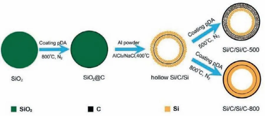
Fig.1.Schematic illustration of the syntheses process of Si/C/Si/C anode materials.
To address the above obstacles,a matryoshka-type carbonstabilized hollow Si (Si/C/Si/C) spheres are synthesized.The Si shell is a porous,polycrystalline products consisting of interconnected tiny nanoparticles and carbon shell is nested layer that ensures good electrical contact and encapsulate Si to restrict SEI formation on the outer surfaces.Such structures possess several attractive advantages: (i) Hollow void allows volume changes of Si nanoparticles inside of inner carbon shell;(ii) Inner carbon shell provides multipoint physical contacts with Si shells,significantly improving the conductivity of electrode;(iii) Outer carbon shell facilitates the formation of stable SEI film;(iv) Amorphous regions in the polycrystalline Si possess good tolerance to intrinsic strain/stress,benefiting for the structure stability.
The syntheses of Si/C/Si/C samples can be divided into two steps (Fig.1).First,highly uniform SiO2nanospheres (Fig.S1 in Supporting information) prepared by hydrolysis of tetraethylorthosilicate (TEOS) [20]are coated with a polydopamine (pDA)through self-polymerization of dopamine in solution.After carbonized the pDA under inert atmosphere,the aluminothermic reaction is conducted between carbon-coated silica (SiO2@C,Fig.S2 in Supporting information) and aluminum powder in AlCl3/NaCl mixture.The hollow Si/C/Si nanospheres are obtained (Fig.S3 in Supporting information) after the removal of Al-bearing byproducts,leaving amounts of mesopores.The silicon hollow structures can be formed by a diffusion mechanism in the molten salts.In molten AlCl3/NaCl,a large amount of ion and solvated electrons are producedviaan ionization process [21],Al=Al3++3e−,which etches SiO2to break the Si-O bond to form SiOx.Then,the SiOxis reduced in the molten salts and grows on the surface of carbon layerviathe previously documented diffusion mechanism[20,22,23],leading to the formation of the Si/C/Si hollow structure.Herein,the NaCl is adopted as heat scavenges,which effectively prevents the hollow structure collapsing and avoids the aggregation of Si nanoparticles [24].Next,the hollow Si/C/Si nanospheres are encapsulated by another pDA shell,and then undergo an annealing process at 500 °C and 800 °C to form an outer carbon shell.For the sake of clarity,the annealed hollow Si samples at 500 °C and 800 °C are denoted as Si/C/Si/C-500 and Si/C/Si/C-800 from now on,respectively.
The X-ray diffraction (XRD) patterns of the Si/C/Si/C-500 and Si/C/Si/C-800 are shown in Fig.2a.The 2θpeaks located at 28.5°,47.4°,56.2°,69.3° and 76.5° are indexed to the diffraction peaks of cubic Si (PDF#27–1402),confirming the successful conversion SiO2to Si [21].The Raman spectroscopy of two samples is shown in Fig.2b.The peak at 521 cm−1for Si/C/Si/C-800 is assigned to the transverse optical mode of crystalline silicon [17,25].Compared to the Raman absorption peak of crystalline Si,the peak of Si/C/Si/C-500 exhibits a blue-shift peak at around 518 cm−1,indicating the appearance of amorphous silicon (a-Si) phase [25–28].Our previous reports confirm that the appearance of a-Si is due to low synthesis temperature [29].The peaks at 1341 and 1582 cm−1,correspond to the D and G bands of carbon,respectively [30].The negligible signals of carbon indicate a very thin coating layer.
To observe the effect of anneal temperature on the microstructure of Si products,the nitrogen gas sorption data of Si/C/Si/C-500 and Si/C/Si/C-800 are collected (Figs.2c and d).The specific surface area (SSA) of Si/C/Si/C-500 (Fig.2c) is 64.1 m2/g based on the Brunauer-Emmett-Teller theory,which is higher than that of Si/C/Si/C-800 sample (25.3 m2/g).This is probably due to the coarsening of pores and silicon phases in the high-temperature annealing process [29].The hypothesis is also supported by the increase of the average pore diameter by elevating the calcination temperature (10.9 nm for Si/C/Si/C-500vs.12.7 nm for Si/C/Si/C-800).The result means that the low-temperature is beneficial for the preservation of porous structure.
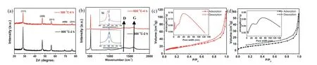
Fig.2.(a) XRD and (b) Raman results of Si/C/Si/C-500 and Si/C/Si/C-800 nanospheres,respectively (Inset of b is the enlarged Raman adsorption peak of Si);Nitrogen adsorption and desorption isotherms of (c) Si/C/Si/C-500 and (d) Si/C/Si/C-800 samples,respectively (Insets are corresponding pore width distributions).
Fig.3 shows the morphologies of Si/C/Si/C-500 and Si/C/Si/C-800 samples.SEM and TEM images demonstrate that two samples have a hollow spherical structure.However,the microstructure of shell layers changes after annealing at different temperature.As observed in Fig.3a,the Si/C/Si/C-800 exhibits a spherical shape with a smooth surface and without massive or agglomerated Si nanoparticles observed.TEM images (Fig.3b) show the detailed microstructure of the Si/C/Si/C-800.The shell layer becomes more compact.Inset image in Fig.3b exhibits that homogeneous element with same light intensity are concentrated in the shell.The linear distributions can reflect the content change of different elements,so it can be used as an indicator of structure.Fig.S4(Supporting information) exhibits the corresponding linear distributions of Si/C/Si/C-800 sample along with the hollow shell.It can be seen that the intensity of Si element (green line) only has one peak when the line scanning gets through the hollow shell.Besides,the intensity of carbon has no obvious change.These results reveal that the Si/C/Si/C sandwiched structure disappears.This is due to the reduction of defects (including pores and amorphous regions) after high-temperature annealing [31].It is also confirmed by the ordered lattice fringe in the high-resolution transmission electron microscopy (HRTEM) image (Fig.3c) and the selected area electron diffraction (SAED) result (inset image in Fig.3c) [24].The interplanar distances are measured to be 0.31 nm,which corresponds to the (111) crystal planes of the cubic Si [32].In comparison,the Si/C/Si/C-500 samples also have a typical spherical morphology (Fig.3d),but the outer surface becomes much rougher which is comprised of large amount of tiny Si nanoparticles (Fig.S5 in Supporting information).Significantly,TEM images in Fig.3e show the microstructure of Si/C/Si/C-500.Inset image in Fig.3e exhibits the clear Si-C interface with Si/C/Si/C multi shells.The thin Si shell can shorten the diffusion path of Li+during lithiation.Moreover,double carbon shell encapsulates Si nanoparticles and provides sufficient physical contact points,which can largely enhance the conductivity of the composites.The ambiguous lattice fringes of shell in the HRTEM image (Fig.3f) indicate the appearance of a-Si.SAED (the inset of Fig.3f) of Si/C/Si/C-500 is circular rings,also indicating the polycrystalline nature [33].The porous,amorphous regions can effectively buffer the volume variation during lithiation/delithiation,inhibiting the material pulverization and enhancing the structure stability.To confirm the constituents of the shell,the element mapping and the linear distribution are also conducted along the hollow shell (Fig.3g).The element mapping(Figs.3g1 and g2) confirms the existence of Si (Fig.3g1) and carbon (Fig.3g2).The corresponding linear distribution (Fig.3h) reflects the content change of silicon and carbon.The intensity of Si appears two peaks along the scanning line.It is worth noting that the intensity of carbon slightly increases between two peaks of Si.Both sides of shell,the signal intensity of carbon has no significant change.It indicates the outer carbon layer is a uniform coating.In brief,the above results demonstrate the matryoshka-type hollow structure of Si/C/Si/C-500,in which pores and amorphous phases are preserved in silicon layers.The formation of different Si structures is typically driven by chemical potential differences associated with curvature effects on the particle interfacial energies [34].At elevated temperature,the thermally activated processes (e.g.,crystallite rotation and alignment) become dominant.The rearrangement of atom contributes to the transformation from amorphous to crystalline Si.And pores tend to coalesce and disappear.However,at low temperature,the threshold for crystallite intergrowth or diffusional mass transport is severely limited.
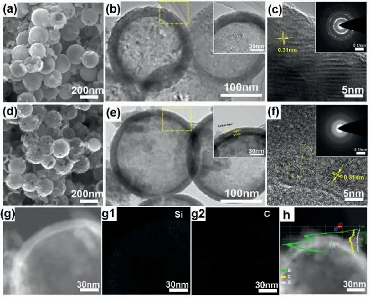
Fig.3.Microstructure of (a-c) Si/C/Si/C-800 and (d-g) Si/C/Si/C-500 nanospheres.(a) SEM,(b) TEM (Inset is the magnified region of the yellow rectangle in (b)) and (c)HRTEM images of the Si/C/Si/C-800 (Inset is the SAED of the hollow shell).(d-f) The corresponding structure characterization of Si/C/Si/C-500 as same as Si/C/Si/C-800.(g)STEM image and the corresponding element mapping of (g1) Si,(g2) C,(h) linear distributions of Si (green line),C (yellow line) and O (white line) elements of Si/C/Si/C-500.
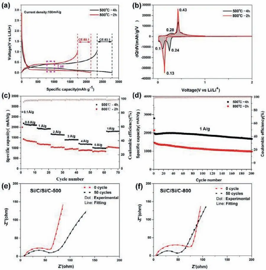
Fig.4.(a) The initial charging/discharging profiles of Si/C/Si/C-500 and Si/C/Si/C-800 at 0.1 A/g current density.(b) Plots of the differential capacity versus voltage.(c) Rate and (d) long-term cycling stability of Si/C/Si/C-500 and Si/C/Si/C-800 electrodes.Electrochemical impedance spectra of (e) Si/C/Si/C-500 and (f) Si/C/Si/C-800 before cycling and after 50 cycles.
The electrochemical performances of the anode based on Si/C/Si/C-500 and Si/C/Si/C-800 are examined in half cells for LIBs.Fig.4a shows the galvanostatic discharge/charge voltage profiles of the first cycle at a current density of 0.1 A/g.The Si/C/Si/C-500 electrode delivers a high discharge capacity of 2797.4 mAh/g with an initial coulombic efficiency (ICE) of 83.1%,and the discharge profile exhibits two obvious platforms at 0.24 and 0.10 V.The lower platform derives from the alloying of crystalline Si,and the higher one from amorphous Si [35,36].However,there is no apparent platform observed at around 0.24 V for Si/C/Si/C-800 electrode,indicating that the high temperature destroys the newly formed amorphous Si during annealing.The Si/C/Si/C-800 electrode displays a lower ICE (80.1%) and discharge specific capacity (2136.1 mAh/g).This is due to that the Si/C/Si/C-800 cannot maintain good integrity owing to the insufficient inner voids and large strain/stress.The voltage hysteresis (ΔE) between the lithiation and delithiation platform for Si/C/Si/C-500 anode is 0.20 V,which is smaller than that with Si/C/Si/C-800 anode (0.36 V).This indicates that the cell has a better reversibility and less polarization [37,38].The above results are also evidenced by the differential capacityversusvoltage (dQ/dV) plots in Fig.4b.At first glance,the area arranged by Si/C/Si/C-500 is larger than that of Si/C/Si/C-800,which indicates the Si/C/Si/C-500 electrode delivers a higher specific capacity,consisting well with the result in Fig.4a.For Si/C/Si/C-500 electrode,there are two cathodic peaks at around 0.24 and 0.1 V in the first discharge process,which corresponds to the lithiation of amorphous Si and crystalline Si,respectively [35].Two anodic peaks at around 0.28 and 0.43 V are related to the de-alloying steps of LixSi [39,40].On the contrary,the Si/C/Si/C-800 displays only one cathodic peak (∼0.13 V) and one anodic peak(∼0.43 V),corresponding to the crystal property [41].When applied different current density,the Si/C/Si/C-500 electrode exhibits excellent rate capability (Fig.4c).It delivers reversible capacities of 2119.4,1929.6,1649.7,1398.5,1184.5,997.7 mAh/g at 0.5,1,2,3,4,5 A/g,respectively.Most notably,a high specific capacity of 1799.8 mAh/g is preserved when the current density reverses back to 1 A/g.This performance is superior to Si/C/Si/C-800 electrode.Compared to the Si/C/Si/C-800,the Si/C/Si/C-500 electrode exhibits an outstanding cycling performance,as shown in Fig.4d.After 200 cycles at 1 A/g,the Si/C/Si/C-500 displays a high capacity of 1673 mAh/g with a capacity retention of 86.9%.The capacity decay ratio is as low as 0.066% for each cycle.The electrochemical performance of Si/C/Si/C-500 in this work can be competitive to others nanostructured Si which are summarized in Table S1 (Supporting information).However,the Si/C/Si/C-800 electrode displays low retention of 68.3% and fast capacity decay.
To further understand the mechanism for the superior electrochemical performance of Si/C/Si/C-500,electrochemical impedance spectra (EIS) data are collected to analyze the internal resistance and charge-transfer process of the pristine and cycled electrodes.Figs.4e and f display Nyquist plots of the Si/C/Si/C-500 and Si/C/Si/C-800 electrodes before and after 50 cycles.Before cycling,the two electrodes show similar Nyquist plots,involving a single semicircle at high-medium frequency region and an inclined line at low frequencies.Apparently,the radius of the semicircle for Si/C/Si/C-500 is smaller than that of Si/C/Si/C-800,which represents the lower charge transfer resistance (Rct) [42].This is ascribed to its unique matryoshka-type design to enhance the electrical conductivity.The equivalent circuit shown in Fig.S6 (Supporting information) is used to fit the Nyquist plots and the fitted data are summarized in Table S2 (Supporting information).Similar to the pristine electrode,the cycled electrodeRctof Si/C/Si/C-500 displays a smaller variation,indicating stable charge transfer and interface.In contrast,the Si/C/Si/C-800 shows dramatically decreasedRctvalue,demonstrating a progressive electrolyte infiltration and activation process [43].The excellent electrochemical performance of Si/C/Si/C-500 electrodes,on one hand,benefits from the porous and amorphous regions on mitigating the volume variation.On the other hand,carbon coated hollow shell provides multipoint contact with Si nanoparticles for good electronic conductivity,and accelerates the charge transfer and kinetics of Li+in the electrode.
To evaluate its potential practical application,a full battery is fabricated with prelithiated Si/C/Si/C-500 anode and commercial Li(Ni1/3Co1/3Mn1/3)O2(NCM) cathode.The capacity ratio of N/P(negative/positive) was about 1.08:1 based on the capacity matching of the full cell.The prelithiation of Si/C/Si/C-500 was carried out through a discharge process in a half-cell and the cutoff voltage is 0.01 V.The cycling performance of the Si/C/Si/C-500//NCM full cell is shown in Fig.S7 (Supporting information) between 2.80 V and 4.25 V.The Si/C/Si/C-500//NCM full cell delivers a high initial capacity of 135.3 mAh/g at 100 mA/g.Moreover,the full battery exhibits a reversible capacity of 99.7 mAh/g with excellent retention.However,the ICE is only 49.6%,indicating that more times prelithiation are necessary to enhance the performance of the Si-based full cells.
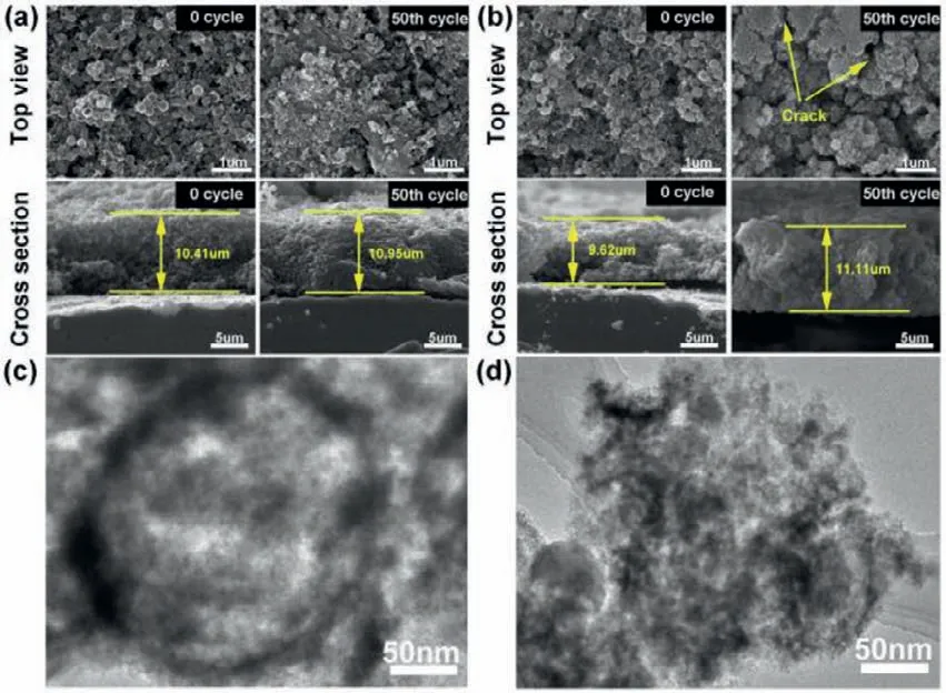
Fig.5.Morphology characterizations of Si anodes before and after 50 cycles.SEM images of top view and cross section based on (a) Si/C/Si/C-500 electrodes and(b) Si/C/Si/C-800 electrodes.TEM images of (c) Si/C/Si/C-500 nanospheres and (d)Si/C/Si/C-800 nanospheres after 50 cycles at 1 A/g.
To further investigate the electrochemical stability of Si/C/Si/C-500,the morphology of electrodes is unveiled before and after 50 cycles (Fig.5).Fig.5a shows the top-view images of Si/C/Si/C-500 electrodes.After 50 cycles,the electrode maintains intact and active materials coalesce admirably,no obvious cracks are observed.This suggests Si/C/Si/C-500 retains structural integrity and stabilize the SEI on the surface.The morphology of the Si/C/Si/C-500 with and without SEI is examined by SEM (Fig.S8 in Supporting information).These nanospheres are covered by a thin and uniform SEI layer,and the morphologies are largely unchanged compared to those of the original Si/C/Si/C-500 nanospheres (Fig.S8a).SEM images of cross sections reveal that the thickness of 50thcycled electrode is very close to the pristine electrode (10.95vs.10.41 μm,respectively).This result is also confirmed by the morphology of Si/C/Si/C-500 hollow spheres after 50 cycles (Fig.5c).The spherical shape is still retained,revealing the superior mechanical property of carbon coating.As for Si/C/Si/C-800 electrodes,large amounts of agglomerations and cracks appear on the surface after 50 cycles(the arrow regions in Fig.5b).Moreover,the SEI damage on the surface is very serious (Fig.S8b).The electrode thickness increases from 9.62 μm to 11.11 μm,reflecting a huge volume variation.The hollow structures break down after 50 cycles as shown in Fig.5d.
These above results prove that the Si/C/Si/C-500 sample gives excellent electrochemical performance which can be attributed to its hollow matryoshka-type strategy.First,the nested carbon shell provides both efficiently conductive paths and mechanical support,ensuring the stable surface charge transfer;Second,thin Si shell inside of carbon shell with multipoint physical contacts,considerably decreases diffusion length of Li+ions;Third,amorphous Si shows good tolerance to intrinsic strain/stress;Four,outer carbon shell facilitates the formation of stable SEI and improves the coulombic efficiency,rate capacity performance.Hence,some crucial issues of Si anodes can be resolved by using the synergy effect based on structure design.
In summary,we demonstrate that through a low-temperature aluminothermic reaction and annealing process,matryoshka-type carbon stabilized hollow Si can be designed and synthesized successfully.The obtained Si/C/Si/C-500 anodes have significantly improved rate capacity and initial coulombic efficiency (83.1%).Impressively,the electrode can retain a reversible specific capacity of 997.7 mAh/g at 5 A/g current density.Such excellent electrochemical performance is ascribed to the good volume buffering effect,good mechanical stability and high conductivity during the charge/discharge process.This proposed approach can be widely employed to prepare porous hollow nanomaterials based on huge volume variation.
Declaration of competing interest
The authors declare that they have no known competing financial interests or personal relationships that could have appeared to influence the work reported in this paper.
Acknowledgments
This work was supported by the National Science Foundation of China programs (Nos.52007110,22078179,21901146),Key Research and Development Program of Shandong Province(No.2019GGX103027),and Taishan Scholar Foundation (No.tsqn201812063).
Supplementary materials
Supplementary material associated with this article can be found,in the online version,at doi:10.1016/j.cclet.2021.10.039.
 Chinese Chemical Letters2022年6期
- Chinese Chemical Letters的其它文章
- Photochemical defluorinative functionalization of α-polyfluorinated carbonyls via spin-center shift
- Methods of screening,monitoring and management of cardiac toxicity induced by chemotherapeutics
- Light-guided tumor diagnosis and therapeutics: From nanoclusters to polyoxometalates
- Nanofluidics for sub-single cellular studies:Nascent progress,critical technologies,and future perspectives
- Effective purification of oily wastewater using lignocellulosic biomass:A review
- Recent advances in microchip-based methods for the detection of pathogenic bacteria