
Metal-organic frameworks derived carbon-coated ZnSe/Co0.85Se@N-doped carbon microcuboid as an advanced anode material for sodium-ion batteries
2022-07-11 03:39XioynLiXioqinLiuYuXingQiojiZhengXijunWeiDunminLin
Chinese Chemical Letters 2022年6期
Xioyn Li,Xioqin Liu,Yu Xing,Qioji Zheng,Xijun Wei,Dunmin Lin,∗
a College of Chemistry and Materials Science,Sichuan Normal University,Chengdu 610066,China
b State Key Laboratory of Environment-Friendly Energy Materials,School of Materials Science and Engineering,Southwest University of Science and Technology,Mianyang 621010,China
Keywords:Transition metal selenides N-doped ZIF-8/ZIF-67 Carbon coating Sodium ion batteries
ABSTRACT Transition metal selenides attract significant attention as advanced anode materials for sodium-ion batteries (SIBs) in recent years due to their appropriate working potential and high theoretic capacity.However,the poor structural stability and rate capability limit their further practical applications.Herein,zeolite imidazole framework-8/zeolite imidazole framework-67 is used as a template to prepare Co0.85Se and ZnSe nanoparticles embed in N-doped carbon matrix successfully,and then coated a carbon layer(ZCS@NC@C) by in-situ polymerization.One side,the N-doped carbon matrix with rich pore structure not only shorten the diffusion path of Na+ and improve the conductivity of the electrode,but also prevent structural collapse and agglomeration of active particles during the sodium insertion/extraction process.On the other side,the carbon shell preparation by coating can form a protective layer to buffer the volumetric stress generated in the electrochemical process and further improve the electrical conductivity.As a result,the as-prepared ZCS@NC@C anode material exhibits an excellent electrochemical performance for SIBs.This investigation provides a promising approach to optimize the electrochemical performance of SIBs by incorporating active metal compounds into conductive carbons to form multidimensional structure.
In recent years,electrochemical energy storage and conversion systems such as lithium/sodium ion batteries (LIBs/SIBs) [1–5],lithium-sulfur batteries (LSBs) [6–8],electrocatalysis [9,10]and supercapacitors (SCs) [11–13]have attracted more attention.In particularly,LIBs have been widely application due to their high energy density and long cycle life [14,15].However,the low abundance of lithium resources and uneven geographical distribution lead to the high cost of LIBs,which hinder the further largescale application of LIBs.Therefore,many researchers have shown more enthusiasm in SIBs with a wide distribution of resources and low cost [16].However,it is difficult for Na+to be reversibly inserted/extracted from the matrix material due to its larger ionic radius (Na+/Li+=1.06 ˚A/0.76 ˚A),which results in low specific capacity and poor electrochemical stability,thus limiting the practical application of SIBs.
At present,developing advanced anode materials with high efficiency sodium storage performance is the key to solve the drawback of SIBs,such as carbon materials [17–19],alloy materials [20],transition metal chalcogenides (TMCs) [21–25].As an important member of TMCs,the transition metal selenide (CoSex[26–28],Sb2Se3[21],FeSe2[29],MoSe2[30],ZnSe [31]) based on the energy storage mechanism of conversion reaction is considered to be a very promising SIBs anode material because of high bulk density,theoretical capacity and excellent rate performance.For example,Luet al.grew ZnSe ultrafine nanoparticle clusters on both the inner and outer sides of hollow porous carbon spheres (ZnSe@HCNs),which can maintain a capacity of 361.9 mAh/g after more than 1000 cycles at 1 A/g [32].Liet al.prepared a novel composite material consist of CoSe and porous carbon polyhedron (CoSe@PCP),and when used as the anode material for SIBs,which showed a reversible capacity of 341 mAh/g after 100 cycles at 100 mA/g [33].Unsatisfactorily,ZnSe and CoSe as high-performance electrodes for SIBs also have disadvantages such as large volume expansion and unstable structure during repeated electrochemical cycles,which may lead to wicked structural collapse of the material and poor cycle stability [26,34].Therefore,it is necessary to design a more robust electrode structure to accommodate the volume changes during Na+insertion/desorption [35–37].
Metal-organic frameworks (MOFs) as an important class of porous inorganic-organic hybrid crystals have attracted widespread attention in recent years [38–43].The anode materials of SIBs obtained by MOFs as precursors have the advantages of adjustable composition and rich pore structure.Some nitrogen-containing organic ligands (such as 2-methylimidazole) can form a nitrogendoped carbon matrix after thermal decomposition,thereby improving the conductivity and electrochemical activity of the electrode material [44].The rich pore structure can increase the contact area between the active material and the electrolyte,thus promoting the transport of Na+[45].For example,Jiaet al.[34]prepared hollow N-doped carbon nanocube-modified ZnSe nanoparticles (ZnSe/HNC) using MOFs as the precursor.The porous structure of the material can buffer the volume change,and the Ndoped carbon matrix can increase the conductivity of the material.Therefore,it can obtain excellent electrochemical performance when used as the anode material of SIBs.
Herein,zeolite imidazole framework-8/zeolite imidazole framework-67 (ZIF-8/ZIF-67) bimetallic MOFs were used as a template to prepare Co0.85Se and ZnSe nanoparticles uniformly distributed in an N-doped carbon matrix coated with a carbon shell (ZCS@NC@C)viaa high-temperature pyrolysis and selenization process simultaneously.The advantages of as-prepared ZCS@NC@C with unique composition and porous structure for SIBs are as following: (1) The highly dispersed Co0.85Se and ZnSe nanoparticles are evenly embedded in the N-doped carbon matrix,effectively preventing the agglomeration of the active nanoparticles;(2) The carbon shell can confine the active particles inside it and buffer the dramatic volume changes caused by repeated insertion/extraction of Na+,thereby improving the structural stability and electrochemical stability;(3) The rich pore structure of ZCS@NC@C exposes more active sites and increases the contact area between the active particles and the electrolyte,which is beneficial to the transmission of Na+and the improvement of capacity.Therefore,the as-prepared ZCS@NC@C exhibits excellent long-term cycle stability and rate capability,which exhibited a discharge capacity of 331.1 mAh/g after 130 cycles at 1.0 A/g,and the rate capability of 320.2 mAh/g is maintained at a high current density of 5.0 A/g,which is equivalent to 80% of 0.1 A/g.Such outstanding electrochemical performance proves that we have successfully proposed a novel modification method to improve the sodium storage performance of anode materials obtained by using MOFs as precursors.
We first prepared ZIF-8/ZIF-67 microcuboid as precursor and microstructure template by room temperature deposition method:Firstly,Zn(NO3)2·6H2O (0.446 g) and Co(NO3)2·6H2O (0.146 g) were dissolved in deionized water (40 mL) to obtain solution A.2-Methylimidazole (1.3 g) and PVP (0.3 g) were added into deionized water (40 mL) and magnetically stirred for 30 min to obtain solution B.Next,the latter was added to the former dropwise,and then keeps stirring for another 5 min.After that,the stirred mixture was aged at room temperature for 8 h.Finally,the powders were washed repeatedly with deionized water several times and collected by centrifugation,and the obtained product was dried at 60 °C.Then,the polymeric resorcinol-formaldehyde(RF) is uniformly grown on the surface of ZIF-8/ZIF-67 byin-situcarbon coating (ZIF-8/ZIF-67@RF): ZIF-8/ZIF-67 (0.2 g),deionized water (14 mL) and ethanol (6 mL) were mixed at room temperature.After stirring magnetically for 30 min,CTAB (0.23 g),resorcinol (0.035 g) and ammonia solution (0.1 mL) were successively added.30 min later,formaldehyde (0.06 mL) was added.After 8 h,ZIF-8/ZIF-67@RF can be obtained by washing repeatedly with deionized water.Finally,ZCS@NC@C is obtained through hightemperature carbonization and selenization processes: put the ZIF-8/ZIF-67@RF in the middle of the porcelain boat,then put the selenium powder on both sides of the same porcelain boat and place the porcelain boat in the middle of the tube furnace,where Se:ZIF-8/ZIF-67@RF:Se=1.5:1:1.5.Selenization was carried out at 800 °C for 3 h in an Ar/H2(95:5,v/v) mixed atmosphere,with a heating rate of 2 °C/min.For comparison,ZCS@NC was prepared through a similar route by using ZIF-8/ZIF-67 as precursor.
The microstructure of the samples was observed by scanning electron microscopy (FEI/quanta250) and transmission electron microscopy (FE-TEM,G2F20,USA).A field emission scanning electron microscope (Zeiss/sigma 500) equipped with an energy dispersive spectroscopy detector was used to test energy-dispersive spectrum (EDS).The characterization of phase structure was examined by X-ray powder diffraction (XRD,Smart Lab,and Rigaku with Cu Kαradiation).The chemical bonds of the materials were characterized by X-ray photoelectron spectroscopy (XPS,PHI 5000).The specific surface area and the pore property of the samples were obtained by the multipoint Brunauer-Emmett-Teller (BET,ASAP2020HD8 Surface Area and Porisity Analyzer) based on the N2adsorption-desorption isotherms principle.The carbon content was obtained by thermogravimetric analysis (DSC-TGA,Q500,American TQ Company).The Raman spectroscopies were measured by Raman spectrometer (Renishaw RM2000,UK,with a 512 nm laser wavelength operated at a power of 5 mW).
The CR2032 coin-type cell was assembled in a glove box filled with argon (O2<0.5 ppm,H2O<0.5 ppm) for electrochemical test.The working electrode is prepared with copper foil as the current collector and the active material,acetylene black and PVDF mixed in methyl pyrrolidone (NMP) at a mass ratio of 7:2:1,and sodium foil is the counter electrode.The electrolyte consisted of a solution of 1 mol/L sodium trifluoromethanesulfonate(NaCF3SO3) in DIGLYME (1:1,v/v).Glass fiber membrane was used as the separator (Whatman,GF/A).The CV and EIS were tested on the CHI 660E electrochemical workstation.The galvanostatic charge/discharge tests were measured by an automatic battery test system in the potential range of 0.01–3 V (vs.Na/Na+) at room temperature.
The preparation process of the ZCS@NC@C microcuboid is depicted in Scheme 1.The ZIF-8/ZIF-67 and ZIF-8/ZIF-67@RF were obtainedviaa facile room-temperature co-precipitating method and anin-situpolymerization process,respectively.After a onestep carbonization and selenization process,the ZCS@NC@C can be easily obtained.It has been known that the ZIF-8/ZIF-67 have strong hydrophilicity on the surface due to the presence of terminal N–H functional groups [46].Therefore,the hydrogen bond on the surface of the ZIF-8/ZIF-67 and the hydroxyl group on the surface of resorcinol can be coordinated to obtain the ZIF-8/ZIF-67@RF.The purpose of introducing the RF coating layer is to stabilize the structure of MOFs during high-temperature heat treatment,and to form a carbon shell to improve the conductivity and stability of the electrode material for SIBs.
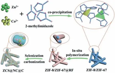
Scheme 1.Schematic illustration of the preparation process of the ZCS@NC@C.
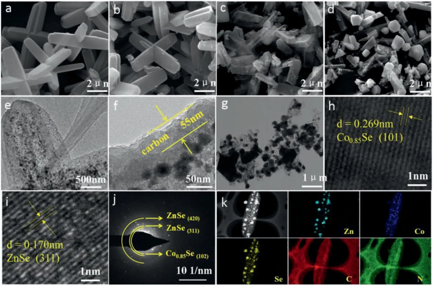
Fig.1.Morphology and microstructure of the precursors,ZCS@NC@C and ZCS@NC: SEM images of (a) ZIF-8/ZIF-67,(b) ZIF-8/ZIF-67@RF,(c) ZCS@NC@C and (d) ZCS@NC.TEM images of (e,f) ZCS@NC@C and (g) ZCS@NC.(h,i) HRTEM images of ZCS@NC@C.(j) SAED image of the ZCS@NC@C.(k) Elemental mapping images of the ZCS@NC@C.
From Fig.1a,the ZIF-8/ZIF-67 microcuboid with uniform particle size and smooth surface is successfully prepared,which exhibit about 6 μm in length and 1.2 μm in width.The surface of the materials obtained after RF coating is slightly rough,but the structure change is not obviously (Fig.1b).Due to the limitation and protection of RF,the structure of ZCS@NC@C obtained after selenization and carbonization maintain well (Fig.1c).However,the structure of ZIF-8/ZIF-67 without RF coating is severely broken after the selenization and carbonization process (Fig.1d).The comparison results show that the introduction of RF can improve the thermal stability of the MOFs.
From the TEM image of the ZCS@NC@C,the selenide particles are uniformly distributed in the carbon matrix (Fig.1e),and the thickness of the coated carbon layer is about 55 nm (Fig.1f).Different from the ZCS@NC@C,the structure of the ZCS@NC is obviously broken,and the metal selenide particles have obvious aggregation phenomenon (Fig.1g).The above phenomena prove that the introduction of carbon shell can not only improve the thermal stability of the material,but also can work together with the carbon matrix derived from MOFs to prevent the agglomeration of active particles.From Figs.1h and i,the clear lattice fringes with interplanar spacing of nearly 0.269 and 0.170 nm can be detected,which match with the (101) lattice plane of the Co0.85Se and (311) lattice plane of the ZnSe,respectively.Moreover,the SAED pattern(Fig.1j) shows the polycrystalline characteristics of ZCS@NC@C,in which two diffraction rings can be matched to the (420) and (311)crystal planes of ZnSe,and the other one diffraction ring can be indexed to the (102) crystal plane of Co0.85Se.The elemental mapping image of Se corresponds to Zn and Co,which also indicates the successful synthesis of selenide in the ZCS@NC@C.We further tested the element contents in the samples by using inductively coupled plasma (ICP).The contents of Zn,Co and Se elements in ZCS@NC@C are 26.66%,7.68% and 41.29%,respectively (Table S1 in Supporting information).The elemental mapping images of the C and N elements indicate that the N element is uniformly incorporated in the carbon matrix (Fig.1k).The uniform distribution of Zn,Co,Se,C and N in the ZCS@NC can be also seen from Fig.S1 (Supporting information).Furthermore,energy dispersive spectrometer(EDS) patterns (Fig.S2 in Supporting information) can also reveal the successful incorporation of N in ZCS@NC@C and ZCS@NC.Fig.S3 (Supporting information) shows the XRD patterns of the ZIF-8/ZIF-67 and ZCS@NC@C.The diffraction peaks of the ZIF-8/ZIF-67 are consistent with previous reports (Fig.S3a) [47],demonstrating the successfully preparation the ZIF-8/ZIF-67.All diffraction peaks of the ZCS@NC@C are indexed to the hexagonal Co0.85Se (JCPDS No.52–1008) and ZnSe (JCPDS No.37–1463) without any impurity peaks (Fig.S3b).The diffraction peaks of ZCS@NC are similar to that of ZCS@NC@C (Fig.S4 in Supporting information),indicating that RF coating would not affect the crystal structure of the ZCS@NC.
The chemical compositions and surface electronic state of ZCS@NC@C is detected by XPS.Through the overall survey spectra,the elements of Zn,Co,Se,C,N and O exist in the material(Fig.2a).It is worth noting that the element O can be attributed to the exposure of the sample in the air [31],while the element N is derived from organic ligands at high-temperature pyrolysis process.The two prominent peaks can be observed at 1020.78 and 1043.88 eV from Fig.2b,belonging to Zn 2p3/2and Zn 2p1/2,respectively [36].The high-resolution Co 2p spectrum is shown in Fig.2c.The peaks of Co 2p3/2and Co 2p1/2for Co3+are located at 779.57 and 795.99 eV,respectively.The binding energies of Co 2p3/2and Co 2p1/2for Co2+are 781.35 and 800.42 eV,respectively,while the binding energies of the two satellites are 785.39 and 805.10 eV,respectively [27,48,49].The two peaks at 53.78 and 55.74 eV in Se 3d spectrum corresponding to Se 3d5/2and Se 3d3/2,respectively.The peaks at 58.88,59.78 and 60.78 eV are caused by Co 3p and Se-O bonding on the surface of the composite (Fig.2d)[37].The high-resolution spectrum of C 1s is presented in Fig.2e,the apparent peak at 283.78 eV is assigned to the delocalized sp2hybrid carbon or graphite-like C–C bond,and the other two peaks at 284.88 and 288.28 eV are derived from the C–O and C=O bonds produced during the annealing process [36].Finally,the N 1s highresolution spectrum in Fig.2f shows the presence of pyrrolic N(397.48 eV),pyridinic N (399.98 eV) and graphitic N (403.68 eV).In general,the doping of N can enrich conjugated electrons and promote electronic conduction,thereby enhancing electrochemical performance,especially rate capability [31].
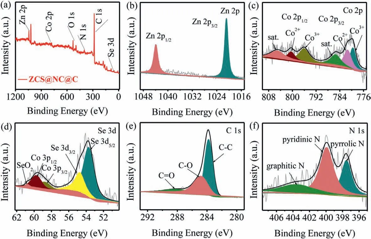
Fig.2.XPS spectra of the ZCS@NC@C: (a) full-range,(b) Zn 2p,(c) Co 2p,(d) Se 3d,(e) C 1s and (f) N 1s spectra.
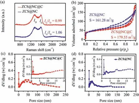
Fig.3.(a) Raman spectra of the ZCS@NC@C and ZCS@NC.(b) Nitrogen adsorptiondesorption isotherms and (c,d) pore size distribution curves of the ZCS@NC@C and ZCS@NC (the insets show an enlargement for low pore sizes).
According to the TGA curves (Fig.S5 in Supporting information),the quality of ZCS@NC@C and ZCS@NC has a slight loss when the temperature is lower than 400 °C,which could be attributed to volatilization of bound water and adsorbed water in the composites.The combustion of carbon in the products caused the rapid mass decay of ZCS@NC@C and ZCS@NC at 407–700 °C and 400–700 °C,respectively,which confirmed that ZCS@NC@C has a better thermal stability.The mass percentage of carbon in ZCS@NC@C and ZCS@NC accounted for 20.32% and 12.83%,respectively.Raman spectra (Fig.3a) are used to further analyze the chemical state of carbon in the composite materials.The peaks located at 1347 and 1580 cm−1are caused by the defect-induced (D) band of the amorphous carbon and the (G) band associated with the bond-stretching mode of the planar sp2-c atoms of the crystalline graphite,respectively.Obviously,theIG/IDratio of the ZCS@NC@C(0.99) is lower than that of the ZCS@NC (1.06),indicating that the ZCS@NC@C has more defects,which is beneficial to promote the transmission of e−/Na+.The specific surface areas of the materials are detected by N2adsorption/desorption isotherms (Fig.3b).The hysteresis loops in the N2adsorption/desorption curves of the ZCS@NC@C,ZCS@NC between the medium to high-pressure regions (p/p0range: 0.4–1) are all type IV isotherms [32],and the specific surface areas are 179.55 and 161.28 m2/g,respectively.In addition,the pore structure characteristics of the products are studied using the pore size distribution curves (Figs.3c and d).The ZCS@NC@C and ZCS@NC are all micropores and mesopores coexisting and the pore volumes are 0.22 and 0.21 cm3/g,respectively.Generally,large surface area and pore volume are beneficial to facilitate electrolyte permeation and provides more activity sites for the migration of Na+,thereby promoting the sodium storage performance.
Fig.4a collects cyclic voltammograms (CV) curves for the first 5 scans of the ZCS@NC@C electrode with a scan rate of 0.2 mV/s in the voltage range of 0.1–3 V.During the first cathode scan,the larger reduction peak at 0.94 V is due to the first intercalation of Na+to form NaxZnCo0.85Se,and the small reduction peak at 0.43 V is attributed to the further combination of Na+and NaxZnCo0.85Se to convert to Zn,Co and Na2Se and the formation of solid electrolyte interface (SEI) film [50–52].The corresponding initial anode scanning process displays two distinct oxidation peaks at 1.0 and 1.72 V,respectively.The small oxidation peak at 1.0 V is attributed to the conversion reaction of Zn [52],while the oxidation peak at 1.72 V corresponds to the conversion of Co to Co0.85Se [50].Evidently,in the next cycles,both the cathode peaks and the anode peaks are shifted to higher potentials,which indicated that the electrode dynamics is enhanced.The good overlap of the CV curves after the first circle indicates that the electrode has excellent electrochemical reversibility and cycle stability.
The charge-discharge platforms of the ZCS@NC@C at the current density of 100 mA/g match well with the redox peaks of the CV result (Fig.4b).The initial charge/discharge capacities are 416.8/507.3 mAh/g,respectively,and the corresponding initial coulombic effi-ciency (ICE) is 83.43%.Part of the capacity loss is due to the formation of SEI film during the first cycle and partial irreversible reactions.The initial charge-discharge curve of the ZCS@NC at 100 mA/g is displayed in Fig.S6 (Supporting information),delivering the initial charge and discharge capacities of 387.6/489.2 mAh/g and giving the ICE of 79.23%.The higher initial coulombic efficiency of ZCS@NC@C indicates that ZCS@NC@C has fewer irreversible side reactions during the first charge and discharge process.The higher ICE of ZCS@NC@C indicates that there are fewer irreversible reactions during the initial charge and discharge.Benefiting from the protective effect of the carbon shell,the ZCS@NC@C electrode shows better cycle stability than ZCS@NC at 100 mA/g.It still has a high reversible capacity of 460 mAh/g after 60 cycles(Fig.4c).At the same time,the CE of the whole process is close to 100%.
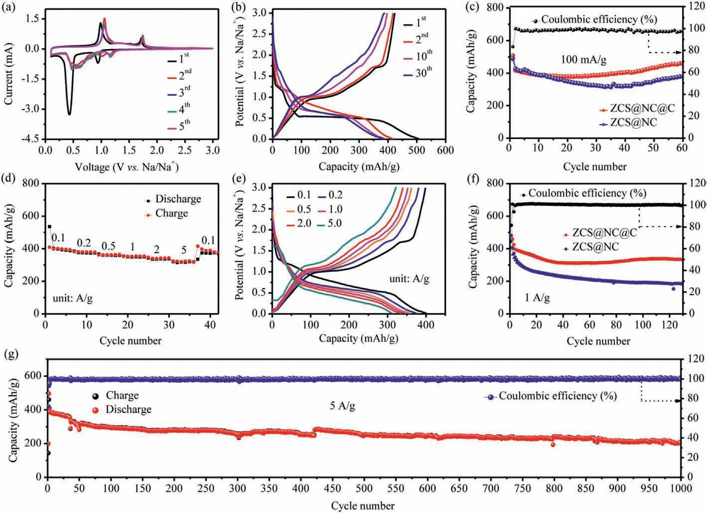
Fig.4.(a) CV curves of the ZCS@NC@C at a scan rate of 0.2 mV/s in the voltage range of 0.1–3 V.(b) Discharge/charge profiles at different cycles of the ZCS@NC@C at 100 mA/g.(c) Cycling performance of the ZCS@NC@C and ZCS@NC at 100 mA/g.(d) Rate performance of the ZCS@NC@C at various current densities;(e) Charge/discharge profiles of the ZCS@NC@C at the various rate from 0.1 A/g to 5 A/g.(f) Cycling performance of the ZCS@NC@C and ZCS@NC at 1 A/g.(g) Long cycling performance of the ZCS@NC@C at 5 A/g.
From Fig.4d,the ZCS@NC@C delivers the rate capacities of 401.7,384.9,366.7,354.5,341.7 and 320.2 mAh/g at 0.1,0.2,0.5,1,2 and 5 A/g,respectively.When the current density is restored to 0.1 A/g,the reversible discharge capacity of 375.6 mAh/g can be recovered.The excellent rate performance of the ZCS@NC@C is also verified by its charge-discharge curves at different current densities.It can be seen from Fig.4e that a significant charge-discharge platform can still be observed up to 5 A/g,indicating that the polarization of the material is slight.This view is also confirmed by the small shift of the redox peak in the CV test in Fig.4a.The long cycle performance of ZCS@NC@C and ZCS@NC at 1 A/g is shown in Fig.4f.ZCS@NC@C still maintains a discharge capacity of 331.1 mAh/g after 130 cycles,and the coulombic efficiency of the electrode except for the first two cycles is always about 100%.In contrast,the ZCS@NC has a much faster capacity reduction and poor cycle performance.From Fig.4g,the ZCS@NC@C exhibits excellent long-term cycling performance at 5 A/g,the capacity is maintained at 201.7 mAh/g after 1000 cycles.
To further explore the effects of pseudocapacitive behavior on the electrochemical reaction kinetics,we perform an electrode dynamics analysis based on CV plots,and the corresponding results are presented in Fig.S7 (Supporting information).The CV curves of the ZCS@NC@C at different scan rates from 0.2 mV/s to 1.2 mV/s are shown in Fig.S7a,all CV curves have similar shapes and the peak current (i) increase with the increase of the scan rate (v) [53],which means that there is obvious pseudocapacitive behavior in the electrochemical process.In general,the peak current (i) and the scan rate (v) are subject to the following equations [26,54].

Whereaandbare adjustable parameters,andbvalue is determined by the slope of log(i) and log(v).Typically,the total capacitive contribution at a given scan rate is provided by diffusion contribution and capacitive contribution,respectively.When thebvalue is close to 0.5,the electrochemical sodium storage process is dominated by ion diffusion behavior;whilebis close to 1,the pseudocapacitance plays a dominant role in the electrochemical sodium storage process.According to the fitting results (Fig.S7b),the values of thebare 0.69,0.71,0.52 and 0.82,respectively,indicating that diffusion and pseudocapacitance coexist during the charging and discharging process for the ZCS@NC@C electrode.Therefore,it is assumed that the total capacity can be divided into diffusion and pseudocapacitance.The contribution percentage of diffusion contribution and pseudocapacitance contribution at a given scan rate can be quantitatively analyzed based on the calculation formula [55]:
k1vandk2v1/2represent pseudocapacitance contribution and diffusion contribution,respectively.As shown in Fig.S7c,the percentage of capacitive contribution at 1.0 mV/s is calculated to be 86.2%.In addition,all contributions of capacitors at different scan rates (0.2,0.4,0.6,0.8,1.0 and 1.2 mV/s) are calculated (Fig.S7d).The contributions of pseudocapacitance contributions gradually increases with the increase of the scan rate (from 74.8% to 87.8%),indicating that the pseudocapacitance contribution plays a crucial role in the overall capacity,especially at high scan rates,which is similar to other transition metal chalcogenides [22,56-58].
Figs.S8a and b (Supporting information) show electrochemical impedance spectroscopy (EIS) of the ZCS@NC@C and ZCS@NC electrodes in fresh and cycled cells,which further reveal the charge transfer kinetics of the electrodes.The analysis is performed according to the equivalent circuit presented in Fig.S9 (Supporting information),whereRfandRctare the contact resistance and charge transfer resistance at the electrode/electrolyte interface,respectively,andRsis the uncompensated solution resistance[29].Before cycling,theRctof ZCS@NC@C (∼2.01Ω) was slightly smaller than that of ZCS@NC (∼3.00Ω),and both increased after 100 cycles at 1 A/g,which is due to the increasing of pulverization and formation of SEI film during the repeated Na-ion insertion/extraction processes.However,the increase of ZCS@NC@C is indeed much lower than that of ZCS@NC,which proves that the introduction of carbon coating can not only increase conductivity,but also has a positive impact on electrochemical stability.From Figs.S8c and d (Supporting information),after 100 cycles,the thickness of the ZCS@NC@C electrode is changed only from∼12.5 μm to ∼14.17 μm,whereas the ZCS@NC electrode experiences a dramatic volume expansion,and the thickness is change from ∼11.67 μm to ∼19.17 μm (Figs.S8e and f in Supporting information).Smaller volume expansion rate of the ZCS@NC@C (11.78%vs.39.12%) further demonstrates the advantages of carbon coating in buffer volume expansion.
In summary,we have rationally designed a ZCS@NC@C composite anode material,in which the Co0.85Se and ZnSe nanoparticles are encapsulated in N-doped carbon matrix,and implemented carbon coating on it.ZCS@NC@C obtained from MOFs precursor can introduce a large amount of pore structure,so that the derivative has a large specific surface area,which can expose more active sites and buffer volume stress.Moreover,the carbon shell acts as a protective layer to prevent the agglomeration of active particles and the crushing of materials,and the doping of N makes the product have a better electronic conductivity.As a result,the ZCS@NC@C material exhibits a high initial specific capacity (555.1 mAh/g at 100 mA/g),outstanding rate capability (320.2 mAh/g at 5 A/g) and excellent long cycle stability (331.1 mAh/g after 130 cycles at 1 A/g).This investigation proposes an effective strategy to optimize the electrochemical performance of electrode materials for SIBs by encapsulation of active nanoparticles into a porous carbon matrix coated with a carbon shell.
Declaration of competing interest
The authors declare that they have no known competing financial interests or personal relationships that could have appeared to influence the work reported in this paper.
Acknowledgments
This work was supported by Sichuan Science and Technology Program (No.2018JY0447) and Project of Southwest University of Science and Technology (No.20zx7142).
Supplementary materials
Supplementary material associated with this article can be found,in the online version,at doi:10.1016/j.cclet.2021.10.014.
 Chinese Chemical Letters2022年6期
- Chinese Chemical Letters的其它文章
- Photochemical defluorinative functionalization of α-polyfluorinated carbonyls via spin-center shift
- Methods of screening,monitoring and management of cardiac toxicity induced by chemotherapeutics
- Light-guided tumor diagnosis and therapeutics: From nanoclusters to polyoxometalates
- Nanofluidics for sub-single cellular studies:Nascent progress,critical technologies,and future perspectives
- Effective purification of oily wastewater using lignocellulosic biomass:A review
- Recent advances in microchip-based methods for the detection of pathogenic bacteria