Stabilization of switched linear systems under asynchronous switching subject to admissible edge-dependent average dwell time*
Linlin HOU ,Xuan MA ,Haibin SUN
1School of Computer Science,Qufu Normal University,Rizhao 276826,China
2College of Engineering,Qufu Normal University,Rizhao 276826,China
E-mail:houtingting8706@126.com;maxuan24@163.com;fengyun198212@163.com
Abstract: The problem of stabilizing switched linear systems under asynchronous switching is addressed.The admissible edge-dependent average dwell time method is applied to design a switching signal that comprises slow admissible edge-dependent average dwell time and fast admissible edge-dependent average dwell time.Under this switching signal,the restriction that the maximum delay of asynchronous switching is known in advance is removed.The constructed Lyapunov function is associated with both the system mode and controller mode.The stabilization criteria and the corresponding algorithm are presented to obtain the controller gains and to design the switching signal.Finally,two examples are given to demonstrate the effectiveness of the proposed results.
Key words: Asynchronous switching;Admissible edge-dependent average dwell time;Multi-Lyapunov function
1 Introduction
In recent decades,switched systems have been widely studied due to their extensive applications in practical systems,such as power electronics systems,stirred tank reactor systems,and network control systems.Subsystems described by a collection of differential or difference equations and the switching signal that specifies the subsystem that is activated at a certain time instant together determine the behavior of a switched system (Liberzon and Morse,1999).Surveys have shown that even if all subsystems are stable,a switched system can be unstable if the switching signal is not appropriate (Zhao et al.,2017;Li et al.,2021).However,even if all the subsystems are unstable,the switched system may be stable if the switching signal is designed reasonably (Xiang and Xiao,2014;Lu and Yang,2020).To date,a vast literature on stability analysis of switched systems has been presented,including Hespanha and Morse(1999),Shorten et al.(2007),Zhao et al.(2012,2015),Zhang XL et al.(2014),Chang et al.(2020),Wang YQ et al.(2021),and Yu and Zhai(2021),to list a few.
A large number of results concerning the control synthesis of switched systems have also been reported (Deaecto et al.,2011,2015;Yuan CZ and Wu,2015;Zhao et al.,2016).In the abovementioned studies,switching between the subsystem and the corresponding controller is assumed to be synchronous.In fact,there is a lag between controller switching and system switching,because it takes some time to identify the system mode and apply the corresponding controller.This scenario is called“asynchronous switching”between the system and the controller.Asynchronous switching may decrease control performance and lead to instability.Therefore,it is necessary to study the stabilization problem of switched systems under asynchronous switching.
In the asynchronous switching scenario,the switching lag of the controller will cause the running interval of the subsystem to be divided into two parts:synchronous switching interval(SSI) and asynchronous switching interval (ASI).In SSI,the controller mode and system mode are the same,while they are different in ASI.The results in the literature indicate that the closed-loop subsystem is stable in SSI and unstable in ASI.Then,combined with the designed time-dependent switching signal,stabilization results were obtained(Zhang LX and Gao,2010;Wang YE et al.,2013;Wang B et al.,2014).However,in fact,the unmatched controller may stabilize the corresponding subsystem in ASI,in which case,the existing results are invalid.
Many techniques have been adopted to design the time-dependent switching signal for the asynchronous switching control problem,for example,the dwell time (DT) method (Sang and Nie,2018;Yuan S et al.,2018),average dwell time (ADT)scheme (Wang XH et al.,2016;Ren HL et al.,2018;Hua et al.,2019;Fei et al.,2020),persistent dwell time(PDT)method(Liu and Wang,2019;Shi et al.,2019),and mode-dependent average dwell time(MDADT) method (Wang B et al.,2014;Fei et al.,2017;Wang YE et al.,2017).In these studies,the maximum asynchronous switching delay is assumed to be known a priori,and is applied to design the switching signal.However,in practice,it is difficult to determine the lag time between system switching and the switching of the corresponding controller.Hence,there is still significant research need for removing this restriction in switching signal design.The admissible edge-dependent average dwell time(AED-ADT) method has been proposed to analyze the stability of the switched systems,and to release the restrictions of MDADT switching (Hou et al.,2018a;Yang JQ et al.,2018).Can this switching signal design method be used to remove the switching signal design restriction under asynchronous switching? If so,how can it be applied? All these questions inspired us to carry out the research presented in this paper.
On the basis of the above analysis,in this paper,the problem of asynchronous switching stabilization is studied for switched linear systems.The contributions are listed as follows:
1.The switching signal is designed by combining the slow AED-ADT (SAED-ADT) method and fast AED-ADT (FAED-ADT) method,assuming that the maximum asynchronous switching delay is not known a priori.
2.The constructed Lyapunov function is associated with both the system mode and controller mode.
3.In the literature (Deaecto et al.,2011,2015;Yuan CZ and Wu,2015;Zhao et al.,2016),it was generally assumed that the controller cannot stabilize the subsystems in asynchronous switching intervals.In this paper,we take a different approach and investigate whether the asynchronous switching controller may be able to stabilize the subsystem in asynchronous switching intervals.
4.The stabilization criteria are obtained,and the corresponding algorithm is presented to determine the controller gains and to design the switching signal.In the simulations,two examples are provided to demonstrate the effectiveness of the proposed results.
2 Problem formulation
Consider the following switched system:

wherex(t)∈Rnis the state andu(t)∈Rpis the input.σ(t),which is the switching signal,is a piecewise constant function taking its value in the finite setM{1,2,...,r},whererstands for the number of subsystems.The setΥ{x(t0);(i0,t0),(i1,t1),...,(im,tm),...|im ∈M,m ∈N}is the switching sequence,where N is the set of natural numbers.Whent ∈[tm,tm+1),thesubsystem is activated.For anyi ∈M,matricesAiandBiare supposed to be known with appropriate dimensions.
The controller is designed as

whered(t) is the lag time satisfying 0<d(t)<tm+1-tm,andKi(i ∈M) is the controller gain to be determined.Substituting Eq.(2)into system(1),we have the following closed-loop system:

whereAσ(t),σ′(t)Aσ(t)+Bσ(t)Kσ(t-d(t))andσ′(t)σ(t-d(t)).
Remark 1System (3) contains two classes of switching signals,i.e.,σ(t) (system mode) andσ′(t)(controller mode).In fact,the effect of the lag timed(t) is that the switching between the system and the controller is not synchronous (Fig.1).The system switches at time instanttm(m ∈N+),where N+N/{0},and the corresponding controller switches attm+d(tm).Consequently,in the intervals[t0,t1)and[tm+d(tm),tm+1),the values ofσ(t)andσ′(t) are the same.However,in [tm,tm+d(tm))(the shadow areas in Fig.1),the values of these two switching signals are different.Here,the time intervals [t0,t1) and [tm+d(tm),tm+1) are called SSIs,and the time interval[tm,tm+d(tm))is called an ASI.Correspondingly,controller (2) is called an asynchronous switching controller.
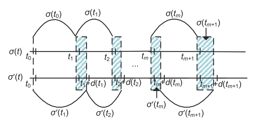
Fig.1 Switching signals σ(t) and σ′(t)
The following definitions will be used in the sequel.
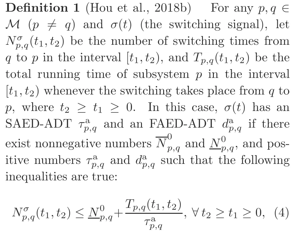

Definition 2(Zhao et al.,2012) The equilibriumx0 of system (1) withu(t)0 is globally uniformly exponentially stable (GUES) under a certain switching signalσ(t) if there exist constantsα >0 andε >0 such that the solution of the system satisfies‖x(t)‖≤‖x(t0)‖,∀t ≥t0.
If an asynchronous switching controller(2) and an AED-ADT switching signal (containing SAEDADT and FAED-ADT) exist such that the developed closed-loop system(3)is GUES,then switched system (1) is stabilized.In this study,the main objective is to design an asynchronous switching controller (2) and an AED-ADT switching signal such that system(1)can be stabilized.
3 Main results
In this section,we present mainly the stabilization results of system (1) under the asynchronous switching controller(2)and the designed AED-ADT switching signal.
For brevity,lettmrepresent the switching instant of the subsystem andtm+d(tm)be the switching instant of the lag controller.In the interval[tm,tm+1),Ts[tm,tm+1)andTu[tm,tm+1)denote the SSI [tm+d(tm),tm+1) and ASI [tm,tm+d(tm)),respectively.Furthermore,letTu↑[tm,tm+1) andTu↓[tm,tm+1) represent the intervals in which the closed-loop subsystem is unstable and stable,respectively.For anyi,j ∈M,denoteΩs{(i,j)∈M×M|t ∈Ts[tm,tm+1)}andΩu{(i,j)∈M×M|t ∈Tu[tm,tm+1)}.Moreover,letΩuwhereΩu↑{(i,j)∈M|t ∈Tu↑[tm,tm+1)}andΩu↓{(i,j)∈M|t ∈Tu↓[tm,tm+1)}.
In the sequel,we give the following result by virtue of AED-ADT switching for system (1).Suppose that subsystemjswitches to subsystemiat instanttm,and that the correspondingjthcontroller switches to theithcontroller at instanttm+d(tm).
Theorem 1Consider system (3).For the given valuesλi <0 (i ∈M) withνi,j >1 ((i,j)∈Ωs),γi,j <0 withμi,j >1 ((i,j)∈Ωu↓),andγi,j >0 with 0<μi,j <1 ((i,j)∈Ωu↑),if there exist matricesPi,i >0((i,i)∈Ωs),Pi,j >0((i,j)∈Ωu),andKi(i ∈M)such that the following inequalities hold:
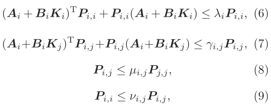
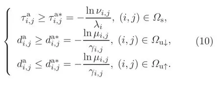
then system(1)is stabilized under the asynchronous switching controller(2)and the AED-ADT switching signal satisfying
ProofSystem(3)can be rewritten as

For system(11),choose the following Lyapunov function:


Whent ∈Ts[tm,tm+1),σ(tm)σ′(tm)i.Then on the basis of inequality (6),one can obtain the following inequality:

Denoteσ(t0)σ′(t0)iwhent ∈[t0,t1).Then from inequality(13),we obtain

Letσ(tm+d(tm))σ′(tm+d(tm))iwhent ∈[tm+d(tm),tm+1).Then on the basis of inequality (13),the following inequality is true:

Denoteσ(tm)i,σ′(tm)jwhent ∈[tm,tm+d(tm)).According to inequality(7),we have

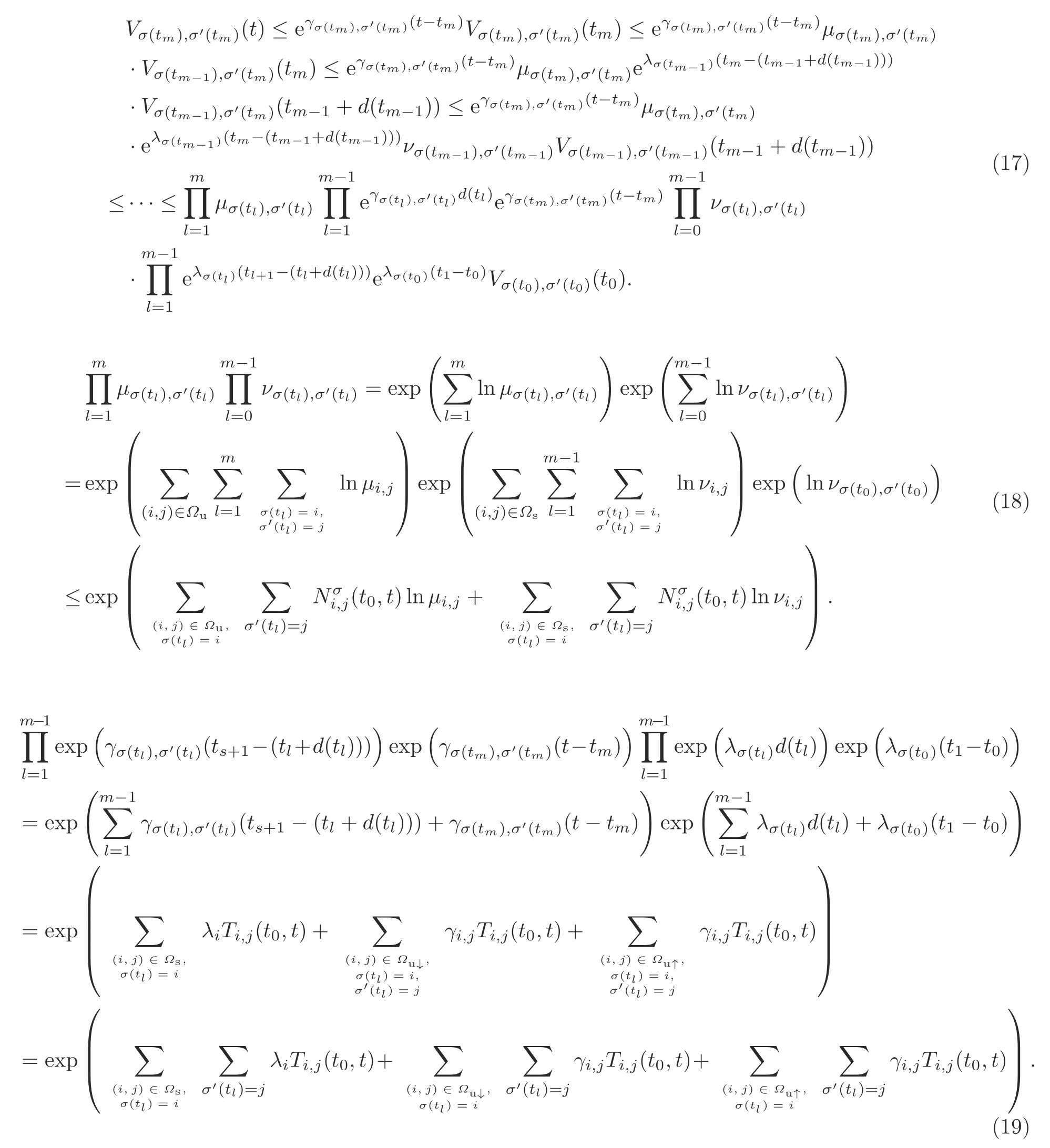
Note thatσ(tm+d(tm))σ(tm),σ′(tm+d(tm))σ′(tm+1),andσ′(t0)σ′(t1).Whent ∈[tm,tm+d(tm)),inequalities (8),(9),and (14)-(16) mean that inequality (17) (on the top of the next page)holds.
Substituting inequality (18) and Eq.(19) into inequality (17) and combining inequalities (4) and(5)yield inequality (20)(on the top of page 815).
It can be verified from Eq.(12)that
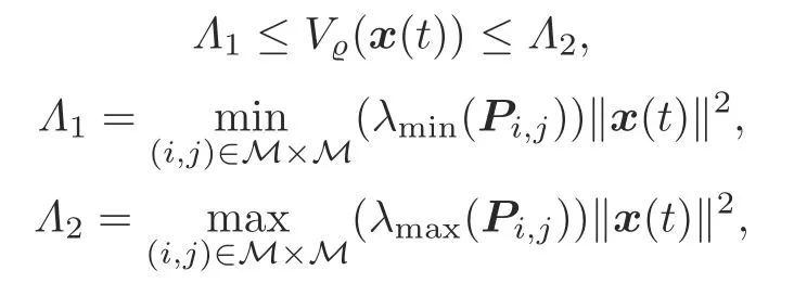
which together with inequality (20)further implies
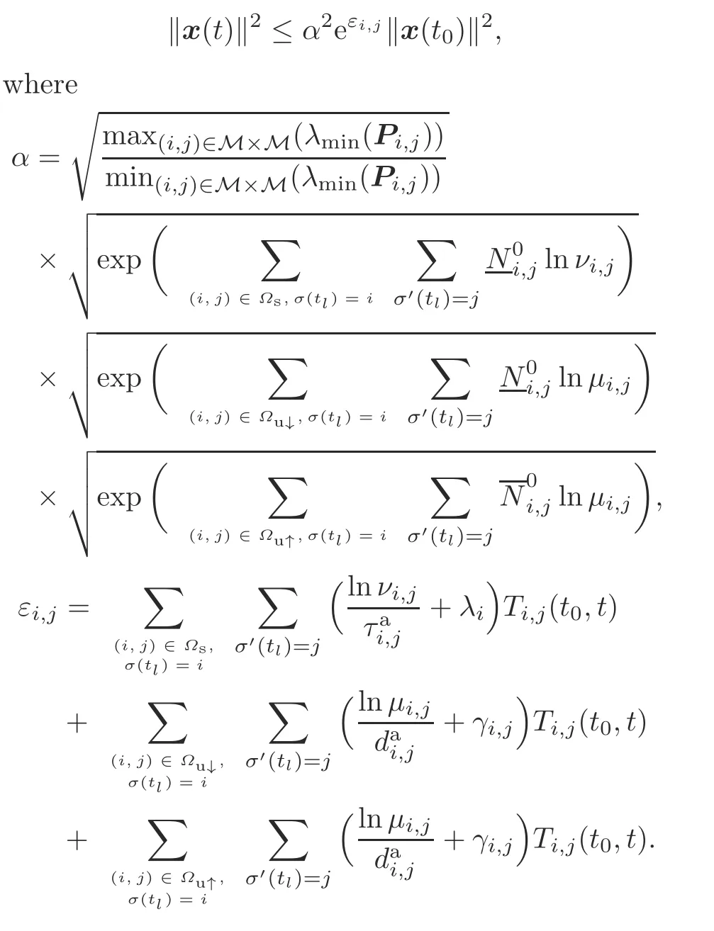
Let
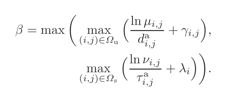
By condition(10),we can determine thatβ <0.Then we have

Moreover,the value ofαis larger than 0.Then from inequality (21) and Definition 2,we conclude that system (3) is GUES,which implies that system (1) is stabilized by controller (2) and switching signal(10).This completes the proof.
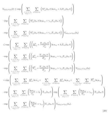
Remark 2In Theorem 1,the stabilization condition is presented for system (1) under the asynchronous switching controller (2).Three different cases are considered to design the corresponding switching signal:
Case 1:theithsubsystem is stabilized by theithcontroller;
Case 2:theithsubsystem is stabilized by thejthcontroller;
Case 3:theithsubsystem is not stabilized by thejthcontroller.
Case 1 means that the switching between the system and the controller is synchronous.In this case,we use SAED-ADT switching to guarantee that the dwell time is as long as possible.Cases 2 and 3 occur when the switching between the system and the controller is asynchronous.In case 2,although the activated subsystem and the controller are mismatched,Ai+BiKjis stable.Hence,SAED-ADT switching is employed.In case 3,the mismatch between the activated subsystem and the controller may cause poor control performance,so FAED-ADT switching is used to ensure that the dwell time is as short as possible.
Remark 3Many studies tackling the problem of asynchronous switching control for various switched systems have a premise that the maximum asynchronous switching delay is assumed to be known a priori (Wang B et al.,2014;Ren W and Xiong,2016;Wang XH et al.,2016;Fei et al.,2017;Wang YE et al.,2017;Wu et al.,2017;Ren HL et al.,2018;Sang and Nie,2018;Yuan S et al.,2018;Hua et al.,2019).In this study,this restriction is eliminated.By virtue of AED-ADT switching (10),the asynchronous switching delayin every interval can be obtained,which is more in line with the demand in practice.
Remark 4In ASIs,both the constructed multi-Lyapunov function and its decay rate are associated with the system mode and controller mode,which is more general than the one in Wang YE et al.(2013).
Remark 5Suppose that at switching instanttm,thejthsubsystem switches to theithsubsystem,and that at switching instanttm+d(tm),thejthcontroller switches to theithcontroller.Then at switching instanttm+d(tm),the energy of the Lyapunov function is allowed to increase (see the square-line area in Fig.2).Furthermore,at switching instanttm,the energy of the Lyapunov function is permitted to increase as long asAi+BiKjis stable (see the slash-line area in Fig.2a).WhenAi+BiKjis not stable,the energy of the Lyapunov function must decrease at switching instanttm(see the slash-line area in Fig.2b).However,the increment is allowable in the ASI (see the dot-dash line in Fig.2b).
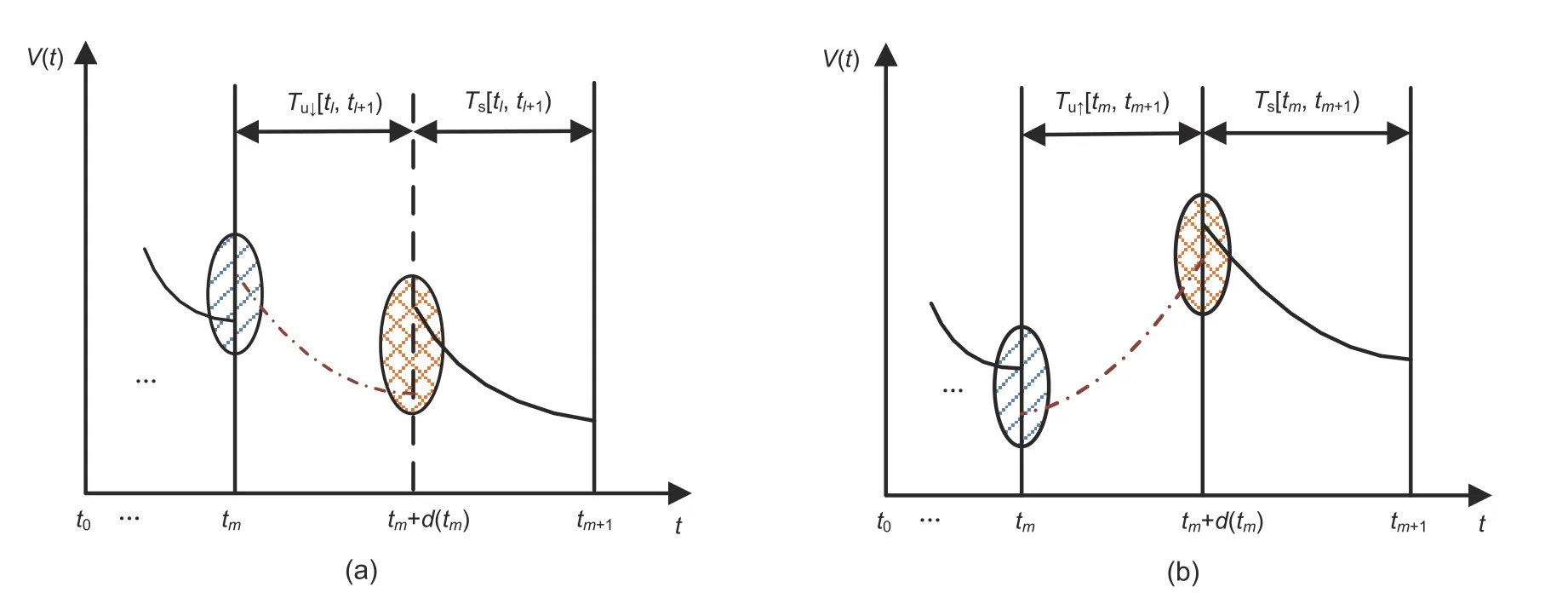
Fig.2 Response curves of the Lyapunov function:(a) Ai+BiKj is stable in [tm,tm+d(tm));(b) Ai+BiKj is unstable in [tm,tm+d(tm))
To obtain the controller gainsKi(i ∈M),we present the following result:
The store owner smiled and whistled and out of the kennel2 came Lady, who ran down the aisle3 of his store followed by five teeny tiny balls of fur. One puppy was lagging considerable behind. Immediately the little boy singled out the lagging limping puppy and said, “What’s wrong with that little dog?”
Theorem 2Consider system (3).For the given valuesλi <0 (i ∈M) withνi,j >1 ((i,j)∈Ωs),γi,j <0 withμi,j >1 ((i,j)∈Ωu↓),andγi,j >0 with 0<μi,j <1 ((i,j)∈Ωu↑),if there exist matricesXi,i >0 ((i,i)∈Ωs),Xi,j >0 ((i,j)∈Ωu),and(i ∈M)such that the following inequalities hold:
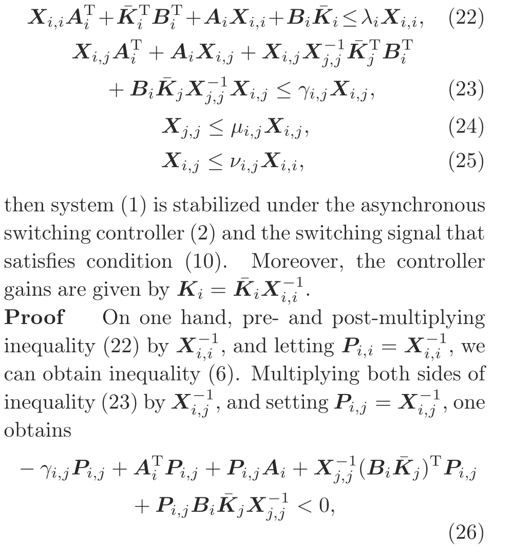
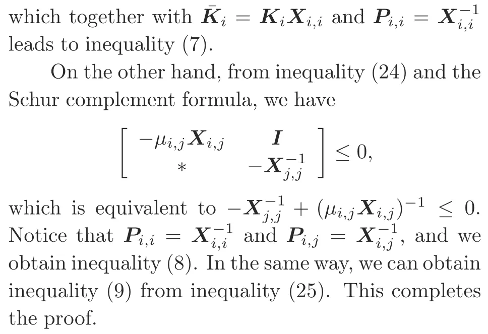
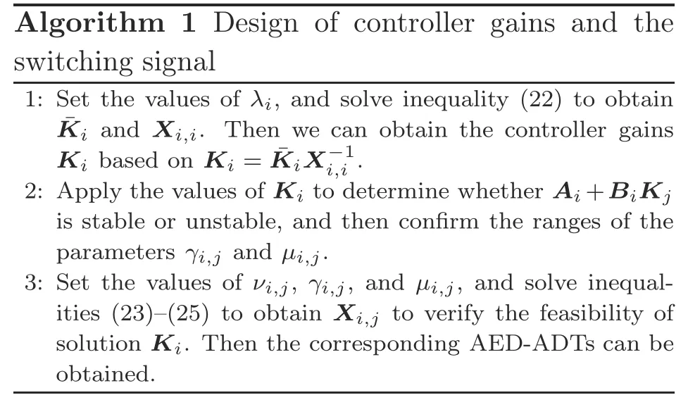
Note that in Theorem 2,condition (23) is nonlinear.In the following,we give an algorithm to obtain the controller gains and to design the switching signal.
Remark 6In Algorithm 1,first of all,controller (2) is designed to guarantee thatAi+BiKi(t ∈Ts[tm,tm+1)) is stable.Then,based on the stability ofAi+BiKj(t ∈Tu[tm,tm+1)),the AEDADT switching signal is designed.In ASIs,if allAi+BiKjare stable,then only SAED-ADT is used;if allAi+BiKjare unstable,then only FAED-ADT is adopted.
In ASIs,when allAi+BiKjare stable,we give the following corollary:
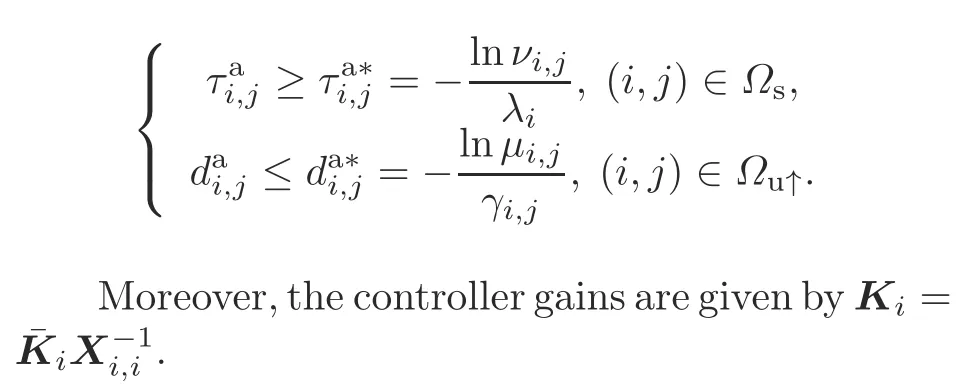
Corollary 1Consider system (3).For the given valuesλi <0(i ∈M)withνi,j >1((i,j)∈Ωs)andγi,j <0 withμi,j >1 ((i,j)∈Ωu↓),if there exist matricesXi,i >0 ((i,i)∈Ωs),Xi,j >0 ((i,j)∈Ωu↓),and ¯Ki(i ∈M) such that inequalities (22)-(25) are true,then system (1) is stabilized under the asynchronous switching controller (2) and the switching signal that satisfies

Moreover,the controller gains are given byKi
In ASIs,when allAi+BiKjare not stable,the following corollary can be obtained:
Corollary 2Consider system (3).For the given valuesλi <0(i ∈M)withνi,j >1((i,j)∈Ωs)andγi,j >0 with 0<μi,j <1((i,j)∈Ωu↑),if there exist matricesXi,i >0 ((i,i)∈Ωs),Xi,j >0 ((i,j)∈Ωu↑),and ¯Ki(i ∈M) such that inequalities (22)-(25) are true,then system (1) is stabilized under the asynchronous switching controller (2) and the switching signal that satisfies
Whend(t)0,that is,the switching between the system and the controller is synchronous,we have the following result:
Corollary 3For any (i,j)∈M × M,i/j,consider system (3).For the given scalarsλi <0 andνi,j >1,if there exist matricesXi,i >0 andsuch that inequality(22)and the following inequality hold:

then system(1)is stabilized under controlleru(t)Kσ(t)x(t)and the switching signal that satisfies

Moreover,the controller gains are given byKi
ProofThe proof process is similar to that of Theorem 2,and thus it is omitted.
4 Examples
Now we provide two examples to show the effectiveness of the main results in this study.
Example 1Consider the switched system (1)consisting of three subsystems.The parameters are as follows:

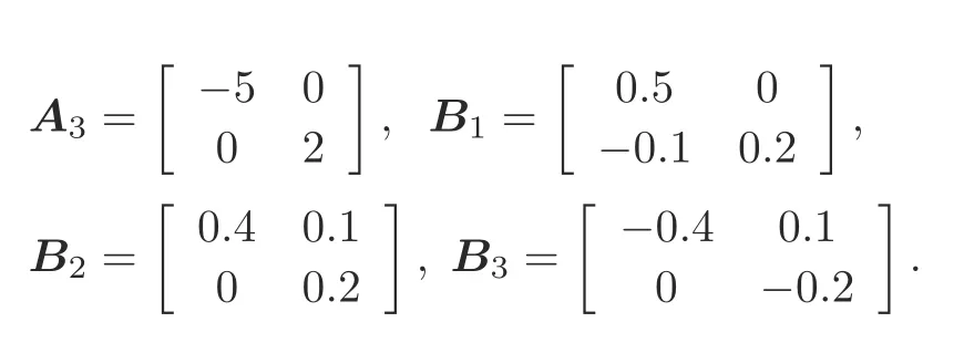
The eigenvalues of matrixA1are 2 and 2,those of matrixA2are-1 and 0.2,and those of matrixA3are-5 and 2,showing that these three subsystems are unstable.On the basis of Algorithm 1,we have the following steps:
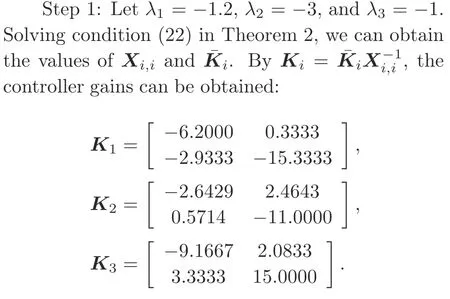
Step 2:The eigenvalues of matricesAi,jAi+BiKjare illustrated in Table 1.The value ranges of the corresponding parametersμi,jandγi,jare also presented in Table 1.From Table 1,we can see that onlyA2,1A2+B2K1is stable,and that the otherAi,jare unstable,which confirms thatμ2,1>1,γ2,1<0,and that the otherμi,jandγi,j(i/j)satisfy 0<μi,j <1 andγi,j >0,respectively.
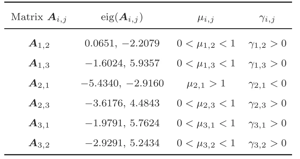
Table 1 Eigenvalues of matrices Ai,j=Ai +BiKj
Step 3:The parametersμi,j,γi,j,andνi,j,and the corresponding AED-ADTs are presented in Table 2.
From Table 2,we have the following conclusions:
Table 2 Parameters νi,j, μi,j, γi,j and AED-ADTs

Table 2 Parameters νi,j, μi,j, γi,j and AED-ADTs
1.In SSIs [t0,t1) and [tm+d(tm),tm+1),m ∈N+,the ADTsτi,jare different based on differentj,even for the same subsystemi.For example,andare both the dwell time on subsystem 1.We can see that they are not equal.
2.In ASIs[tm,tm+d(tm)),m ∈N+,not only the ADTs on the same subsystem are different,but also the adopted switching signals may be different.For example,Table 1 shows thatA2+B2K1is stable but thatA2+B2K3is unstable for subsystem 2.That is,the controlleru(t)K1x(t)can stabilize the second subsystem,but the controlleru(t)K3x(t)cannot.In this case,in the intervals in whichA2+B2K1occurs,SAED-ADT switching is employed (μ2,12>1 andγ2,1-2<0 in Table 2).In cases in whichA2+B2K3is activated,the FAED-ADT switching works (μ2,30.8<1 andγ2,39.5>0 in Table 2).
3.The ADTs in asynchronous switching are not necessarily smaller than the ones in SSIs,especially whenAi+BiKjis stable.For instance,Table 1 shows thatA2+B2K1is stable,and in Table 2,the corresponding ADT is0.3466,which is larger than the ADT0.0608 in SSIs.
Choose the initial valuex(0)[2-4]Tand the periodic switching path 1→3→2→1→3→2→···.Then,under the parameters in Table 2,Fig.3a shows the response curves of statex(t) for the switching signal that satisfies condition(10)with0.06,and0.24.Fig.3b presents the curves of these two signals.From Fig.3,we can see that system (1) can be stabilized by the designed asynchronous switching controller(2) and switching signal (10).The response curve of the Lyapunov functionV(t)is shown in Fig.4.From Fig.4,we can see that on one hand the energy ofV(t) decreases in SSIs[0,0.62),[0.67,1.42),and[1.44,1.53),but increases at the switching instantst1+0.67,t2+1.44,andt3+1.59.On the other hand,at the switching instantst10.62,t21.42,andt31.53,the energy ofV(t)is decreasing.Note that in ASIs [0.62,0.67) and [1.42,1.44),the energy increment ofV(t) is allowed.

Table 3 Eigenvalues of matrices Ai,j=Ai +BiKj
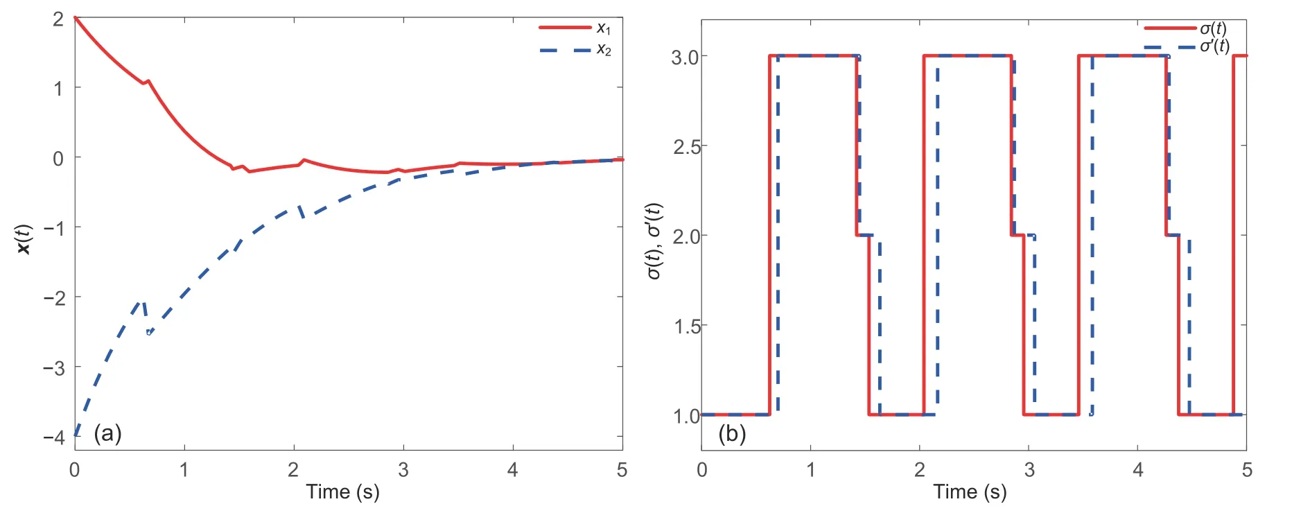
Fig.3 Response curves of x(t) (a) and switching signals σ(t) and σ′(t) (b) for Example 1
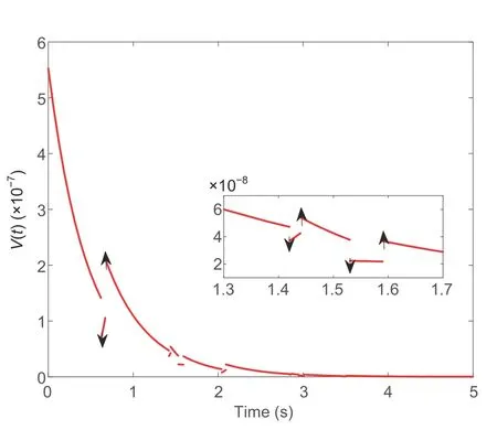
Fig.4 Response curve of V(t) for Example 1
Example 2(Zhao et al.,2014) Consider the tunnel diode circuit presented in Fig.5,which is described by
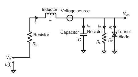
Fig.5 Tunnel diode circuit

In practice,RDis uncertain.SupposeRD1/(0.002+0.01β),whereβ ∈[0,100].Letx1(t)VC(t) andx2(t)iL(t).Then the above tunnel diode circuit can be described by the following
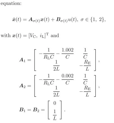
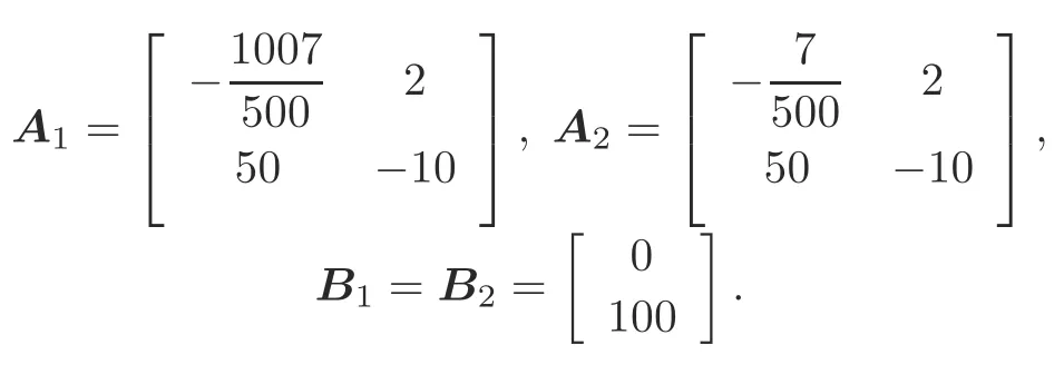
Here,the parameters are given byC0.5 F,L0.01 H,RE0.1 Ω,andRL200 Ω.Thus,we have the following system matrices:
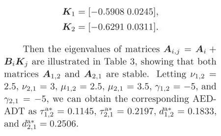
Letλ1-8 andλ2-5.From inequality(22),we can obtain the values of controller gainsKias
Choose the initial valuex(0)[2-4]Tand the periodic switching path 1→2→1→2→···.Fig.6a shows the response curves of statex(t) for the switching signal that satisfies condition(10)with0.18,and0.24.Fig.6b presents the curves of these two signals.From Fig.6,we can determine that system(1)can be stabilized using the designed asynchronous switching controller(2) and switching signal (10).Fig.7 presents the response curve of the Lyapunov functionV(t).
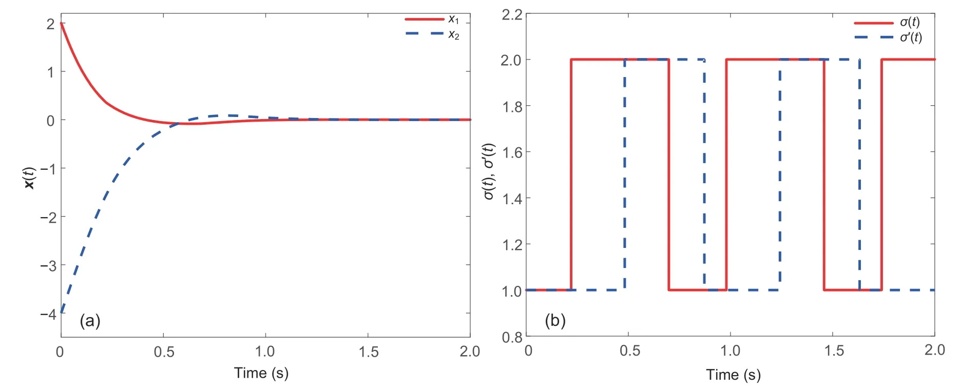
Fig.6 Response curves of x(t) (a) and switching signals σ(t) and σ′(t) (b) for Example 2
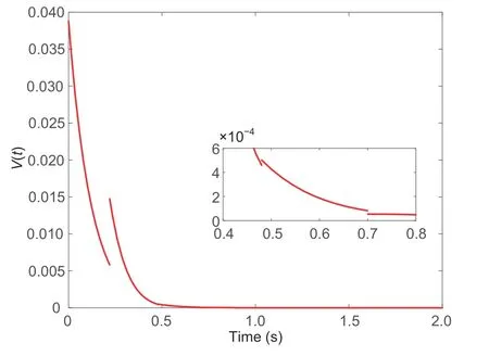
Fig.7 Response curve of V(t) for Example 2
5 Conclusions
This study presents the research on the problem of stabilizing switched linear systems under asynchronous switching.SAED-ADT switching and FAED-ADT switching have been applied in designing the switching signal.Using the multi-Lyapunov function method,stabilization conditions have been given for switched linear systems.An algorithm has also been provided to determine the controller gains and to design the switching signals.Finally,two examples have been given to show the effectiveness of the proposed results.
Note that in the practical automation industry,the occurrence of faults or failures in actuators and/or sensors will lead to degradation of system performance(Yang HY et al.,2018,2021).In the future,we will study fault-tolerant control of switched linear systems under asynchronous switching and actuator failure.
Contributors
Linlin HOU designed the research.Linlin HOU and Xuan MA processed the data.Xuan MA carried out the simulations.Linlin HOU drafted the paper.Haibin SUN helped organize the paper.Xuan MA and Haibin SUN revised and finalized the paper.
Compliance with ethics guidelines
Linlin HOU,Xuan MA,and Haibin SUN declare that they have no conflict of interest.
 Frontiers of Information Technology & Electronic Engineering2022年5期
- Frontiers of Information Technology & Electronic Engineering的其它文章
- Intelligent analysis for software data:research and applications
- Wireless passive flexible accelerometer fabricated using micro-electro-mechanical system technology for bending structure surfaces*
- Shot classification and replay detection for sports video summarization*
- Depth estimation using an improved stereo network*
- Smart grid dispatch powered by deep learning:a survey*
- How to manage a task-oriented virtual assistant software project:an experience report
