Wireless passive flexible accelerometer fabricated using micro-electro-mechanical system technology for bending structure surfaces*
Chen LI ,Mangu JIA ,Yingping HONG ,Yanan XUE ,Jijun XIONG
1Science and Technology on Electronic Test and Measurement Laboratory,North University of China,Taiyuan 030051,China
2Key Laboratory of Instrumentation Science and Dynamic Measurement,Ministry of Education,North University of China,Taiyuan 030051,China
†E-mail:lichen@nuc.edu.cn
Abstract: We propose an inductor-capacitor (LC) wireless passive flexible accelerometer,which eliminates the difficulty in measuring the acceleration on the surface of a bending structure.The accelerometer is composed of a flexible polyimide (PI)substrate and a planar spiral inductance coil(thickness 300 nm),made using micro-electro-mechanical system(MEMS)technology.It can be bent or folded at will,and can be attached firmly to the surface of objects with a bending structure.The principle of radio frequency wireless transmission is used to measure the acceleration signal by changing the distance between the accelerometer and the antenna.Compared with other accelerometers with a lead wire,the accelerometer can prevent the lead from falling off in the course of vibration,thereby prolonging its service life.Through establishment of an experimental platform,when the distance between the antenna and accelerometer was 5 mm,the characterization of the surface of bending structures demonstrated the sensing capabilities of the accelerometer at accelerations of 20-100 m/s2.The results indicate that the acceleration and peak-to-peak output voltage were nearly linear,with accelerometer sensitivity reaching 0.27 mV/(m·s-2).Moreover,the maximum error of the accelerometer was less than 0.037%.
Key words: Bending structure surfaces;Flexible accelerometer;Micro-electro-mechanical system (MEMS) technology;Wireless non-contact measurement
1 Introduction
Recently,a variety of new accelerometers have been rapidly developed and are been widely used in aviation control and navigation,civil medicine,smart phones,automobile safety industries,and other fields(Benmessaoud and Nasreddine,2013;Lee JM et al.,2016;Yamane et al.,2016;Han et al.,2018;Zhang HC et al.,2019,2020;Dwivedi and Khanna,2020;Zhong et al.,2020).Accurate measurement of acceleration is essential for improving the efficiency of the systems.For example,in the bending bearing surface of aero-engines,the measurement of acceleration is related to the life of the bearing.In the medical field,the application of wearable electronic devices for the measurement of human body signals has also been a hot research topic in recent years.Therefore,it is necessary to measure the surface acceleration signal of bending structures.Common accelerometers can be categorized into piezoelectric,piezoresistive,and capacitive types.Yaghootkar et al.(2017) proposed an accelerometer that uses piezoelectric effect to measure acceleration at 10 kHz,and Ghemari and Salah(2018) simulated and designed a silicon-based piezoresistive accelerometer with high accuracy.Based on three-dimensional printing,Zega et al.(2018) combined additive manufacturing and wet metallization technology to build a differential capacitive accelerometer.Compared with other accelerometers,this has better performance in terms of sensitivity and linearity.Piezoelectric,piezoresistive,and capacitive differential sensors are widely used in accelerometers and have excellent performance.However,vibration is measured through the wire,but the wire can easily break during the vibration process.Therefore,these methods are not suitable for some environments.Wireless passive measurement methods are more suitable for the measurement of acceleration.Ma et al.(2017) proposed a low-temperature co-fired ceramic (LTCC)wireless passive gas sensor,and achieved a measured NO2gas concentration of 0.0006‰.Ma et al.(2019)fabricated an LTCC proximity sensor using the principle of inductor-capacitor(LC)resonance.The sensor had good sensitivity and a long detection distance.Lin et al.(2021)developed a wireless passive temperaturepressure sensor based on high-temperature co-fired ceramics (HTCC),which can measure temperature and pressure simultaneously with a single LC circuit.Li et al.(2021) proposed a wireless passive vibration sensor based on HTCC,which can realize vibration measurement at 250 ℃.Although they can achieve non-contact measurement,existing sensors are made mostly of ceramic materials,which are difficult to adhere to the surface of a bending structure in the vibration process,leading to problems such as incomplete adhesion.Due to the flexibility of the base material,a flexible sensor overcomes the disadvantage of the rigidity of traditional electronic sensors and can be attached to the surface of the object to be measured(Lee D et al.,2018;Lee Y et al.,2018;Choi and Ahn,2019;Wang S et al.,2019;Zhu et al.,2019;Zhao and Zhou,2020).Zhang M et al.(2020) fabricated a selfpowered flexible pressure sensor based on a conventional nano patterned polymer film composed of nanocoating and indium tin oxide electrodes.This type of sensor could not only detect changes in pressure or strain,but also acquire energy as a self-powered sensor.Carbon nanotubes (CNTs) (Wang C et al.,2020)and printed interdigital electrodes have been used to fabricate pressure sensors capable of detecting physiological signals in the human body.Presently,flexible sensors are used mainly for stress,pressure,temperature,or humidity measurement,but rarely for acceleration measurement.
In this paper,we propose an LC resonant wireless passive flexible accelerometer which can be used on the surface of a bending structure.First,a flexible inductance coil with a simple structure was fabricated on a flexible polyimide (PI) substrate via micro-electro-mechanical system (MEMS) technology.Thereafter,a wireless passive measurement method was used to avoid disconnection of the accelerometer lead during vibration.A flexible substrate was used to measure the bending structural surface,which is difficult to accomplish with an ordinary wired accelerometer.Finally,an acceleration test was conducted on the vibration platform.The accelerometer functioned normally at accelerations of 20-100 m/s2,and its repeatability error was low.
2 Wireless non-contact measurement method
The wireless passive accelerometer consists of a flexible PI substrate and a planar spiral inductor.As shown in Fig.1a,DinandDoutrepresent the inner and outer diameters of the coils,respectively.DWis the width of the inductance coil,andDSis the distance of adjacent coils.The advantages of this structure are its simple machining process,involvement of low casting,and high efficiency.The parasitic capacitance of the accelerometer consists of the parasitic capacitanceCS1on the adjacent inductance coil and capacitanceCS2on the PI substrate material.The equivalent structure is shown in Fig.1b,and the equivalent circuit model is simplified as shown in Fig.1c,whereLS1andRS1represent the inductance and resistance between the coils,respectively,andRS2represents the resistance generated by the substrate.The simplified circuit of the accelerometer,ignoring the influence of substrate loss,is shown in Fig.1d.The flexible accelerometer can be regarded as an LC resonant circuit in series with a capacitance and an inductance coil.The inductance,resistance,and parasitic capacitance of the coil are expressed asLS,RS,andCS,respectively.
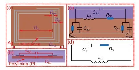
Fig.1 Model (a),structure (b),equivalent circuit (c),and simplified circuit (d) of the flexible wireless passive accelerometer
The principle of a flexible accelerometer based on non-contact measurement is shown in Fig.2.Rr,Lr,andCrrepresent the resistance,inductance,and capacitance of the antenna,respectively.The coupling distance between the accelerometer and the antenna changes due to the acceleration of the accelerometer,which results in a change of the equivalent impedance.The reflection coefficient of the antenna end is then represented by the voltage signal from the detector circuit.The distance between the accelerometer and the antenna can be expressed as
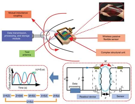
Fig.2 Wireless non-contact measurement method

wheretis the vibration time,ais the acceleration,andxis the initial distance between the accelerometer and the antenna.As the acceleration changes,the coupling coefficient between the wireless passive accelerometer and the antenna can be expressed as (Ji et al.,2019)
wherer1andr2denote the radii of the inductors of the accelerometer and the coupled antenna,respectively.The mutual inductance is determined by the inductances of the antenna and the accelerometer,and the coupling coefficient between the antenna and the accelerometer is

According to Kirchhoff’s voltage theory,the equivalent impedance at the antenna end is(Ji et al.,2019)
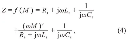
whereωrepresents the angular frequency.According to the impedance characteristics,the reflection coefficient at the antenna end can be expressed as (Zhang GJ et al.,2019)

The reflected signal is converted into a voltage output by the detector circuit:

whereGenvrepresents the amplification gain andC31is the coupling coefficient between the input port and the coupling port of the coupler.It can be seen from the above equations that the capacitance and inductance of the accelerometer and the antenna are all constants,and that the coupling coefficient changes with acceleration.The voltage amplitude can be expressed as a function of the independent variable of acceleration.Thus,wireless measurement of acceleration can be achieved by detecting changes in voltage amplitude.
3 Fabrication of the accelerometer
The main processes of fabricating the wireless passive flexible accelerometer include cleaning,gluing,pre-drying,lithography,development,magnetron sputtering,and cleaning via sonication.Given that the PI is a flexible material,to avoid bending in the fabrication process,a high-temperature resistant adhesive tape was used to attach the PI to the silicon wafer.The accelerometer was then fabricated on the surface of the PI film.As shown in Fig.3,the specific fabrication process was as follows:
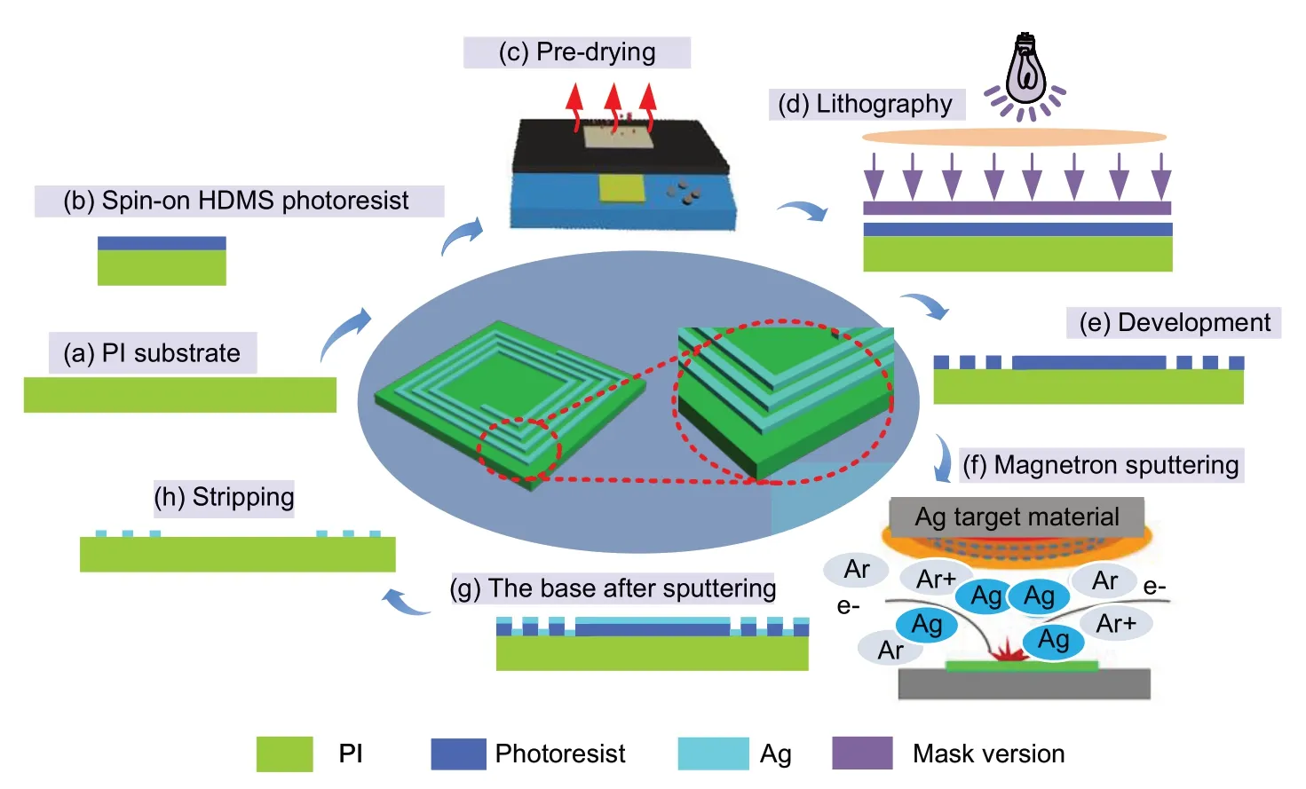
Fig.3 Fabrication of the accelerometer
1.Cleaning:The PI film was cleaned in acetone and ethanol solution for 5 min,rinsed repeatedly with deionized water,and blow dried with a nitrogen gun to ensure that the surface of the substrate was clean and dry.
2.Gluing:The clean substrate was placed in a vacuum oven for 20 min to achieve an even coat of the hexamethyldisilazide (HMDS) adhesive layer to increase the adhesion between the photoresist and the PI;this was done to prevent the subsequent development of photoresist during the development of liquid penetration and the emergence of the gel-off bleaching phenomenon.The positive photoresist AZ6130 was evenly applied on the PI substrate by rotating the gelatinizer,with an average glue speed of 500 r/min for 10 s,and 3000 r/min for 60 s,to obtain a photoresist with a thickness of 2.5 μm.
3.Pre-drying:To evaporate the photoresist in the organic solvents,pre-drying needed to be carried out after rotating the photoresist.The temperature was set to 100 ℃,and the pre-drying time was 90 s.
4.Lithography:The PI film coated with photoresist was placed upward,and the mask plate with lithography pattern placed downward into the lithography machine to ensure that the mask plate and the silicon wafer were fixed.The pattern on the mask printed by the upper capacitor plate was transferred to the PI film at a ratio of 1:1 using the lithography machine of EVG610.
5.Development:The PI film was immersed in an AZ238 series developer for 15-30 s to fully display the substrate surface.
6.Magnetron sputtering:The sputtering power of 400 W was applied for 15 min.When the thickness of the Ag layer reached 300 nm,the sputtering stopped.
7.Upon completion of the sputtering process,the substrate was placed in acetone and ethanol for 10 min,cleaned with deionized water,and dried with nitrogen.Finally,the PI film was removed from the silicon wafer to obtain a flexible accelerometer.
The fabricated accelerometer is shown in Fig.4a.Fig.4b shows the Ag coils after sputtering,as observed under a microscope.Fig.4c shows the Ag inductor and PI substrate,as observed under a confocal microscope.The inner and outer diameters of the accelerometer were 32 mm and 44 mm,respectively.The distance between inductors of the accelerometer was 1 mm.The bending degree of the accelerometer is shown in Fig.4d,which records the flexible accelerometer before bending to a degree of 50%.When the bending degree was changed,the resistance of the accelerometer changed little,and the performance of the flexible accelerometer was still good.Therefore,it was proven that the accelerometer could adhere tightly to the surface of the bending structure,and the acceleration could be measured.
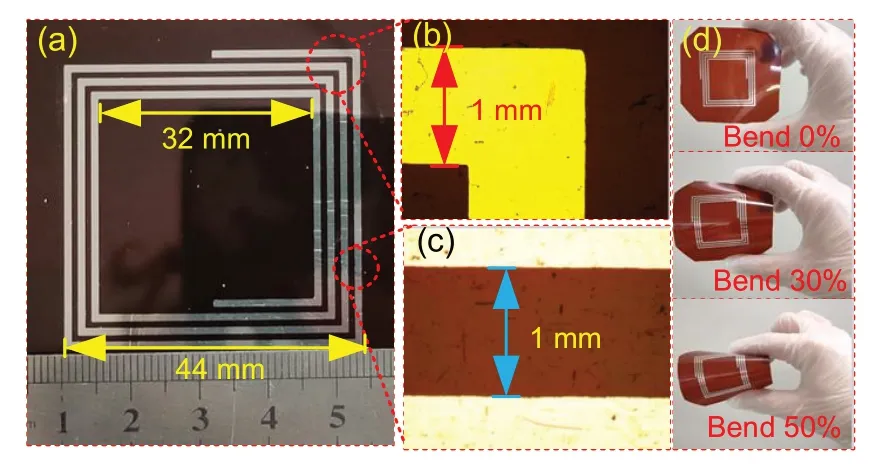
Fig.4 Flexible accelerometer(a),magnified structure of the accelerometer under the microscope (b),distance between inductors of the accelerometer under the microscope (c),and the accelerometer bending to different degrees(d)
Figs.5a and 5b show the appearance of the accelerometer under a confocal microscope.It was evident that the Ag inductor was attached to the PI substrate.Fig.5d shows that the thickness of the fabrication planar spiral inductor was 300 nm.This thickness is very small,and the increased peak distance in this figure was caused by the presence of a photoresist that had not been peeled off completely.
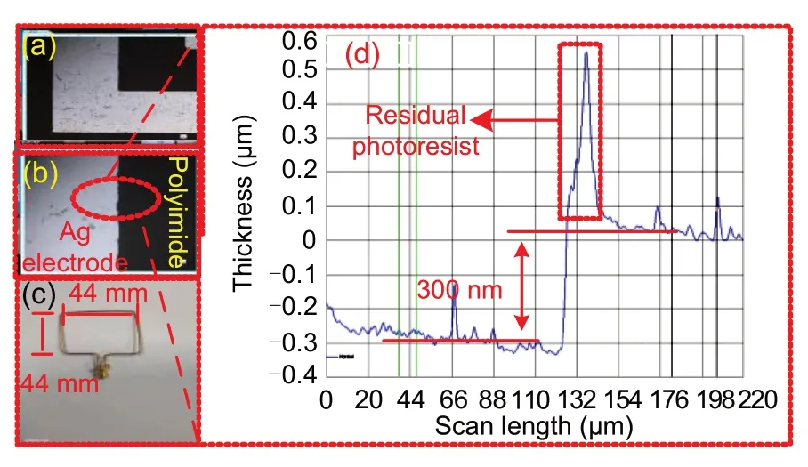
Fig.5 Inductance coil under the confocal microscopy(a),inductor and substrate topography under the confocal microscopy (b),the test antenna (c),and the measured thickness of the fabricated planar spiral inductor(d)
In general,when the size of the test antenna is the same as the outer diameter of the accelerometer inductance coil,the signal intensity is maximized.Therefore,the test antenna shown in Fig.5c was designed,and made with copper wire.The two ends of the pins were connected to the RF SMA connector by welding wires.The antenna was of the same size as the outer diameter of the inductance accelerometer.
4 Measurement and discussion
According to the analysis of the wireless transmission principle of the passive accelerometer in Section 2,when the passive flexible accelerometer reciprocates with the vibration period,its relative position to the reading antenna also changes periodically.Therefore,the effective impedance amplitude of the reading antenna changes periodically.So,in this study,based on envelope detection we designed a characteristic signal detector circuit (Fig.6a) to test the acceleration parameters.This circuit was realized by an ADL5511 chip.The signal to be tested was input to the circuit board (Fig.6b).Through the envelope detection inside the ADL5511 chip and a 1.46 V/V amplifier,it output a voltage signal proportional to the excitation.The circuit provided a wideband input impedance of 50 Ω,and the power supply pin had 100 pF and 0.1 μF parallel capacitors to filter out the high-and low-frequency clutter signals superimposed on the power signal respectively,to stabilize the power supply voltage signal.Fig.6c depicts a waveform diagram of the characteristic signal detection output based on the ADL5511.
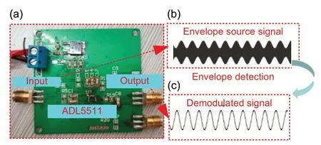
Fig.6 Detector circuit (a),input waveform (b),and output waveform after circuit(c)
The vibration of the accelerometer was tested using a vibration platform(Fig.7a)composed of a vibration table,flexible accelerometer,antenna,signal generator,oscilloscope (general source DS6064),coupler (ZEDC-10-2B),and detector circuit.The platform is illustrated in Fig.7b.A standard vibration sensor was mounted on the surface of the exciter to detect whether the applied excitation was sinusoidal.When the accelerometer did not vibrate,the distance between the antenna and accelerometer was 5 mm.The input end of the coupler was connected to the antenna,and the output end to the signal generator.The CPL port was connected to the RF input end of the detector circuit,and the oscilloscope was connected to the output end of the detector circuit.During the test,the distance between the antenna and the accelerometer changed when the vibration table was excited by another signal generator.Simultaneously,due to electromagnetic mutual inductance coupling,the accelerometer generated an induced magnetic field and reflected signals to the antenna.The antenna input the sensed sinusoidal vibration signal into the detector circuit in the form of an envelope.Then,the detector circuit converted the envelope signal,which contained the information of voltage amplitude,into sinusoidal voltage feed into the oscilloscope.Consequently,the acceleration test of the accelerometer was successfully performed.
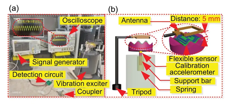
Fig.7 Experimental platform and measurement system(a)and the working principle of the test platform(b)
Fig.8 shows the waveform output by the oscilloscope at 20-100 m/s2.When the acceleration increased,the maximum output voltage amplitude of the oscilloscope also increased.The maximum voltage amplitude at 20 m/s2was 0.018 75 V,increasing to 0.029 95 V when the acceleration reached 100 m/s2.
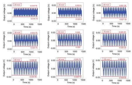
Fig.8 Oscilloscope display of the waveform of the accelerometer at 20-100 m/s2
To express the relationship between the acceleration and the output voltage,the peak voltage points ranging from 20 to 100 m/s2were recorded at 20 Hz with an interval of 10 m/s2.The corresponding function of the acceleration and the amplitude was plotted(Fig.9).The acceleration varied almost linearly with the peak-to-peak value of the output voltage,and the sensitivity of the acceleration was 0.267 mV/(m·s-2).The peak-to-peak values of the oscilloscope output increased with the increase in acceleration,which was consistent with the trend of the amplitude.
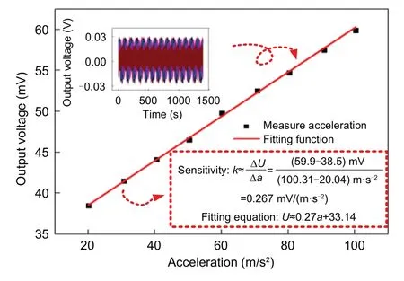
Fig.9 The corresponding function of acceleration and amplitude
To verify the repeatability of the accelerometer,we tested the proposed flexible accelerometer many times,and the changes in the acceleration and peakto-peak voltage of the oscilloscope output were recorded.Fig.10a shows the relationship between the accelerations added in five experiments and the peak-to-peak values of the corresponding voltages.The flexible accelerometer had good repeatability and the sensitivity was 0.27 mV/(m·s-2).Fig.10b records the error points of the five repeatability tests.When the acceleration was 50 m/s2,there was a large error point compared with other accelerations,the error value was 0.03 mV,and the maximum repeatability error of the flexible accelerometer was not more than 0.037%,which may be due to electromagnetic interference in the test environment.
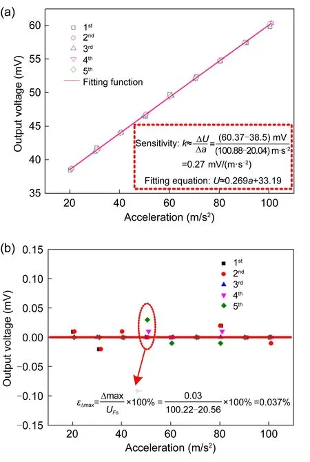
Fig.10 Repeatability test of the accelerometer at 20-100 m/s2 (a) and standard error of the repeatability test of the accelerometer(b)
5 Conclusions
In summary,we have proposed a type of LC wireless passive flexible accelerometer that can be used on the surface of a bending structure.The flexible accelerometer was fabricated using MEMS technology,the substrate was made of flexible PI material,and the thickness of the inductance coil was only 300 nm.Acceleration of 20-100 m/s2at 20 Hz can be measured by the accelerometer.The peak-to-peak output voltage was linear with the change of acceleration.In the acceleration range tested,the average sensitivity was 0.27 mV/(m·s-2),and the repeatability error was less than 0.037%.The wireless passive flexible accelerometer has broad application prospects (such as in human body health monitoring or measuring surfaces of engine bearings) in bending surfaces of structures.
Contributors
Chen LI and Mangu JIA proposed the idea and designed the accelerometer.Yanan XUE fabricated the accelerometer.Mangu JIA measured the accelerometer.Yingping HONG analyzed the results.Mangu JIA drafted the paper.Jijun XIONG made valuable suggestions on the revision;all the authors revised and finalized the paper.
Compliance with ethics guidelines
Chen LI,Mangu JIA,Yingping HONG,Yanan XUE,and Jijun XIONG declare that they have no conflict of interest.
 Frontiers of Information Technology & Electronic Engineering2022年5期
- Frontiers of Information Technology & Electronic Engineering的其它文章
- Intelligent analysis for software data:research and applications
- Stabilization of switched linear systems under asynchronous switching subject to admissible edge-dependent average dwell time*
- Shot classification and replay detection for sports video summarization*
- Depth estimation using an improved stereo network*
- Smart grid dispatch powered by deep learning:a survey*
- How to manage a task-oriented virtual assistant software project:an experience report
