Hierarchical model updating strategy of complex assembled structures with uncorrelated dynamic modes
Chengwei FEI, Hotin LIU, Rhe PATRICIA LIEM, Ytsze CHOY,Lei HAN,*
a Department of Aeronautics and Astronautics, Fudan University, Shanghai 200433, China
b Department of Mechanical and Aerospace Engineering, Hong Kong University of Science and Technology, Hong Kong 999077,China
c Department of Mechanical Engineering, Hong Kong Polytechnic University, Hong Kong 999077, China
KEYWORDS Aeroengine casings;Assembled structures;Correlated mode pair;Hierarchical model updating;Objective function;Uncorrelated modes
Abstract In structural simulation and design,an accurate computational model directly determines the effectiveness of performance evaluation.To establish a high-fidelity dynamic model of a complex assembled structure,a Hierarchical Model Updating Strategy(HMUS)is developed for Finite Element(FE)model updating with regard to uncorrelated modes.The principle of HMUS is first elaborated by integrating hierarchical modeling concept, model updating technology with proper uncorrelated mode treatment,and parametric modeling.In the developed strategy,the correct correlated mode pairs amongst the uncorrelated modes are identified by an error minimization procedure. The proposed updating technique is validated by the dynamic FE model updating of a simple fixed–fixed beam.The proposed HMUS is then applied to the FE model updating of an aeroengine stator system(casings)to demonstrate its effectiveness.Our studies reveal that(A)parametric modeling technique is able to build an efficient equivalent model by simplifying complex structure in geometry while ensuring the consistency of mechanical characteristics; (B) the developed model updating technique efficiently processes the uncorrelated modes and precisely identifies correct Correlated Mode Pairs(CMPs)between FE model and experiment;(C)the proposed HMUS is accurate and efficient in the FE model updating of complex assembled structures such as aeroengine casings with large-scale model, complex geometry, high-nonlinearity and numerous parameters; (D) it is appropriate to update a complex structural FE model parameterized.The efforts of this study provide an efficient updating strategy for the dynamic model updating of complex assembled structures with experimental test data, which is promising to promote the precision and feasibility of simulation-based design optimization and performance evaluation of complex structures.
1. Introduction
Computational models were used to enable performing engineering analyses.Finite Element (FE) modeling and simulation technologies are effective in evaluating structural dynamic characteristics in structural design.FE modeling and simulation can significantly reduce experimental time and costs in the research and development of products, to improve the market competitiveness of products.A high modeling accuracy is thus expected to ensure the effectiveness of evaluating the mechanical characteristics in product design.Generally,structural models can be derived based on FE analysis or modal testing.In most cases,however,achieving a high accuracy of FE models for complex structures is challenging,owing to unavoidable modeling error caused by uncertain factors and excessive assumptions such as the approximation of mechanical characteristics, boundary conditions, nonlinearity,material properties, etc.As such, there have been growing research efforts to develop model updating technologies which aims at reducing the errors between analytical models and test data, to improve modeling accuracy.
In the past thirty years, demand of high computational accuracy promotes the rapid development of structural dynamic model updating techniques, to reduce parameter error and improve FE modeling accuracy by evaluating the correlation of vibration mode between analytical value and experimental value.As such, the final high-fidelity FE model is obtained by iterative optimization.Structural dynamic model updating based on experimental mode data were first investigated in 1971.Collins et al. proposed a systematic FE model updating approach on mass and stiffness matrix by using experimental natural frequencies and modes.In the past decades,research efforts to advance model updating strategies have been at the forefront in structural dynamics in theoretical development and application. Berriet and Cogan employed static test data to update FE model.Imregun et al. discussed the theory and application of FE model updating approaches based on frequency response function data.Ahmadian et al.studied parameter selection strategies in FE model updating and performed modeling and updating of large surface-tosurface joints in the AWE-MACE structure.Chen et al.discussed the structural uncertain dynamic model updating based on response surface model and sensitivity analysis.Mottershead et al. reviewed FE model updating in structural dynamics and proposed sensitivity method for FE model updating by minimizing natural-frequency errors.Sanayei et al. investigated structural static model updating based on test data.Marwala and Sibisi derived an FE model updating strategy using Bayesian framework and modal properties.Zang and Ewins explored model validation of structural dynamics for aeroengine design.Ricci et al.discussed modeling and updating of torsional behavior of an industrial steam turbo generator.Ren et al. analyzed FE model updating based on response surface method for structural statics and dynamics, respectively.Zona et al. performed the FE model updating of timber-concrete composite beams from probabilistic perspective.Wroblewski et al.carried out rotor model updating and validation for an active magnetic bearing based high-speed machining spindle.Schwingshackl et al.performed the modeling and validation of bolted flange joints with nonlinear dynamic behaviors.Modak investigated a model updating technique with respect to uncorrelated modes and demonstrated it on the FE model of a beam structure.Zhai et al. also researched FE model updating technique of complex structures with parametric modeling and static experimental data.The above works contributed to the development of structural dynamic model updating technique. It is noted that the uncorrelated modes indicate that the FE model or analytical modes are not correlated with the experiment modes in fact.
In general, model updating techniques can be categorized into direct methods and iterative methods. Direct methods adopt one-step procedure to make a minimum change in structural matrices.However,the model obtained by this method is typically inefficient in handling vibration spurious modes in model updating.Iterative methods adaptively involve experimentally identified modal data or measured Frequency Response Functions(FRFs)in the model updating procedure.Iterative method is a universal model updating method,owing to it select the appropriate updating parameters from incomplete measured modal data.The key objective in the methods is to reduce the difference between FE modes and experimentally identified modes. The simple structures of iterative methods are particularly attractive among researchers.
However, the iterative method has one challenge in handling complex engineering problems like assembled structure defined as a system consisting of various substructures or components.For example, the stator system of an aeroengine is composed of many casings and multiple bolted joint structures.Therefore, analyzing a complex assembled structure must firstly deals with complex geometry, large-scale FE model, many joint structures and strong coupling among substructures.The complexity limits a high modeling accuracy acquired by the traditional updating strategies. Up to now,we have not yet found the effective updating methods in the model updating of complex assembled structures. Moreover,it is important to identify the correct correlated modes between experimentally identified mode shapes and FE model mode shapes. In stochastic updating of complex structures, mode shape pairs may dynamically change throughout the iterative procedure,because the derived parameters may change at each iteration.The effectiveness of a model updating strategy depends on the correct identification of the correlated pairs.It is thus imperative to seek an efficient method to process uncorrelated modes and accurately recognize correct Correlated Mode Pairs (CMPs) in the dynamic model updating of complex assembled structures.Lastly,modeling the connection between substructures in a complex assembled system like bolted jointseasily incurs large and unacceptable errors.Therefore,it is important to derive an accurate model that can emulate the connection structure in the model updating of complex assembled structures.
To address the above-mentioned challenges,this paper aims to develop a Hierarchical Model Updating Strategy (HMUS)that synergistically combined hierarchical modeling principleand parametric modeling methodinto a novel model updating technology. By decomposing the complex assembled structure into a series of substructures under many layers, these substructures are accurately FE-modeled and updated which can enhance the modeling accuracy of the complex structure once combined.The derived updating strategy is called HMUS which is extended from hierarchical concept in model validationand the reliability design of mechanical assemble relationship.In the proposed HMUS, an efficient model updating technology is developed by introducing an objective function to automatically recognize the correct CMPs of FE model modes and the corresponding test modes,and deal with the uncorrelated modes in the model updating of complex assembled structures. To establish the model of connection structures (i.e., bolted joints) in complex assembled structures, parametric modeling technology is adopted to model the connection structures by the equivalent simplification of mechanical characteristics.
This paper is structured as follows. Section 2 discusses HMUS procedure for the dynamic model updating of complex assembled structures.In Section 3,a model updating technique is developed to handle uncorrelated modes and correctly identify correct CMPs by minimizing an objective function. A detailed model updating of a fixed–fixed beam structure based on testing data is investigated in Section 4,to validate the proposed model updating method. In Section 5, the hierarchical FE model updating of an aeroengine stator system (casings)is discussed to verify the effectiveness of the proposed HMUS.Some conclusions on this study are summarized in Section 5.
2. Hierarchical model updating strategy
Assembled structures are typically characterized by complex geometry,numerous components and multiple design parameters. Deriving a single model to represent the complex structure as a whole typically has a large modeling error.Recently, a distributed collaborative surrogate model method was proposed to improve the efficiency and accuracy of mechanical dynamic assembly reliability design,which was also applied to the probability-based design of other structures by combining advanced surrogate models and intelligent algorithms.This method adopts a layering approach by dividing the complex structure into numerous substructures and models each substructure with a simple model before coordinating the analytical responses of the submodels to obtain the design of the complex large-scale model. The layering approach has recently been introduced into a model updating process to improve the computational efficiency,by decomposing one stochastic updating problem into a series of deterministic ones.The application of the approach to solve experimental validation of a complex and large-scale rigidbody mechanism has also been explored.These works can potentially offer a useful insight into the model updating of complex assembled structures or systems.
The HMUS is proposed to address the dynamic model updating of a complex assembled structure. Following this strategy, the complex assembled structure is decomposed into a series of substructures in multiple layers.These substructures are individually FE-modeled, and subsequently updated. By following this approach, the large-scale complex model of assembled structure with high nonlinearity, strong coupling and numerous parameters is divided into multiple simpler models of substructures with low nonlinearity, weak coupling and fewer parameters, to improve the modeling accuracy of substructures and complex assembled structure. In the proposed HMUS, the model updating technology with uncorrelated modes is developed by introducing an objective function to automatically recognize the correct CMPs of FE model modes referencing test modes. The updating method enables dealing with uncorrelated modes in model updating of complex assembled structures,instead of the traditional model updating methods.For modeling of complex assembled structures with bolted joints,the parametric modeling technologyis adopted by simulating equivalent mechanical characteristics. The basic procedure of HMUS with uncorrelated modes for complex assembled structure is shown in Fig.1.
For the dynamic model of complex assembled structure,the HMUS integrates hierarchical thinking, parametric modeling approach and model updating technique with uncorrelated modes. In the model updating of structural dynamics, it is important to determine the correct CMPs by handling the uncorrelated modes between experiment and FE model. A novel model updating technique considering uncorrelated modes is discussed in Section 3.
3. Model updating theory using modal shapes
In this section, the model updating strategy is presented to properly identify uncorrelated modes, by adopting an optimization problem to minimize the errors between FE model(analytical modes) and experimental modes.
3.1. Correlation analysis of vibration modal data
For a free undamped vibration, motion equation can be described as

where M and K are matrixes of mass and stiffness,respectively;x and ¨x indicate the vectors of displacement and acceleration,respectively. The eigenvalue and eigenvector in Eq. (1) are denoted as λand φrespectively, where the structure is represented by FE models. λand φdenote the eigenvalues and the corresponding eigenvector obtained by modal measurement.Note that A and E in superscripts or subscripts represent the analytical/FE results and experimental data respectively.This convention is used throughout this paper. Experimental eigenvectors from a modal test are typically too complex to directly be applied in updating the undamped model.The correlation between the two sets of eigenvalues and eigenvectors should be improved by model updating. The eigenvalues and eigenvectors of FE model are defined as a function of these updating parameters, i.e.,

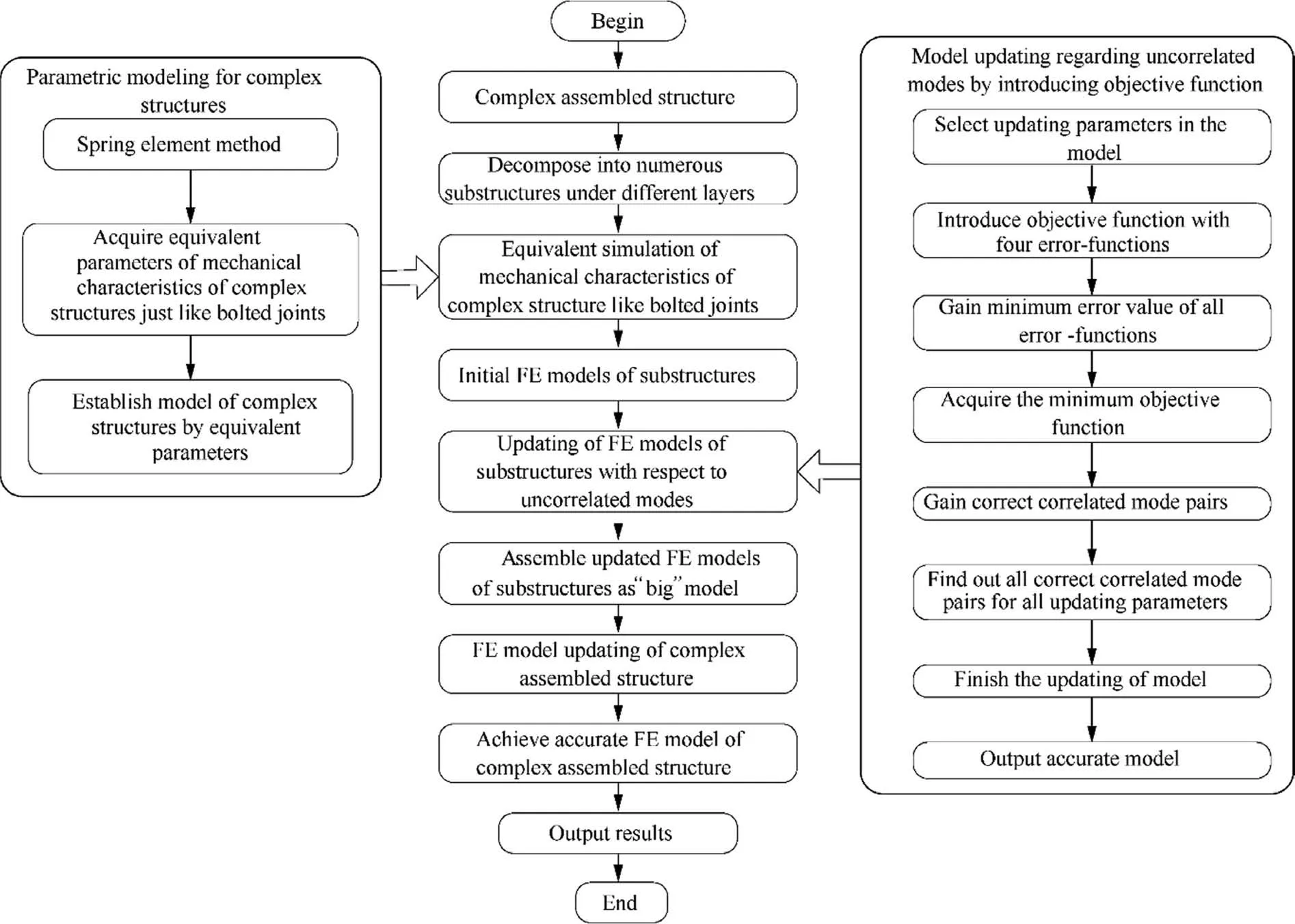
Fig. 1 Hierarchical model updating procedure of complex assembled structure with uncorrelated modes.
where Nrefers to the number of updating parameters selected for FE model updating and u=[u;u;∙∙∙;u]is the vector of updating parameters. These updating parameters correspond to the fractional correction in the physical parameters of the model.In the traditional model updating strategies,the Modal Assurance Criterion (MAC)is commonly used to quantify the degree of correlation. For the pair of ith FE model mode φand the jth measured modes φ, the MAC matrix MAC is

The values in the matrix MAC refer to the mode correlation coefficients indicating the degree of correlation between FE model modes and experimental modes. The values vary between zero and one. MAC=1 indicates an absolute correlation between the pair of modes, whereas MAC=0 denotes zero correlation.Thus,the correlation between the two modes becomes stronger as MAC increases.Reasonable correlation is indicated by a diagonally MAC matrix,where all the diagonal elements are larger than 70% and the off-diagonal elements are less than 10%.Using the information in MAC matrix might lead to erroneous judgment on degree of correlation when there are systemic errors and local modes on the FE model of structures. In some cases, one experimental mode could be correlated with other analytical/FE model modes,such as the previous- or posterior-order modes, instead of the corresponding analytical mode. Thus, relying on MAC matrix alone may lead to incorrect updating of FE models.For symmetrical structures such as disk, cylinder, etc.,[48–51]the MAC values of two similar mode vectors on experiment and FE model are sometime very small,which is not consistent with the actual situation.
The existing updating methods only depend upon precise experimental data and do not focus on the information of uncorrelated modes, resulting in suboptimal models. To address the issues, a novel model updating approach is proposed by considering the FE model updating as a constrained minimization problem.In this optimization problem,an objective function F is minimized subject to boundary conditions to find the optimal updating parameters.
3.2.Objective function of model updating with modal correlation
Let Iand Ibe the indices of percentage error in the FE model eigenvalues corresponding to CMPs and Uncorrelated Mode Pairs (UMPs), while Iand Iindicate the indices of percentage error in the FE model eigenvectors corresponding to CMPs and UMPs. The objective function F can be formulated as a weighted combination of the error indices I,I, Iand I, with the corresponding constant scalar weighting factors ω, ω, ωand ω, respectively. The objective function F is expressed as:

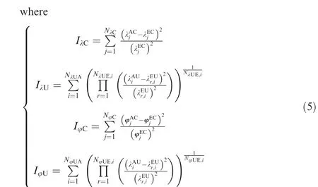
In Eq.(4) and Eq.(5), C and U, both as subscripts and superscripts, correspond to CMPs and UMPs, respectively;the subscripts λ and φ denote eigenvalues and eigenvectors,respectively; Nis the number of eigenvalues corresponding to CMPs which are applied in the function F; Ndenotes the number eigenvalues of FE model modes that are uncorrelated with experimental modes;Nindicates the number of experimental uncorrelated eigenvalues considered as possible correlation with the ith FE model eigenvalue; Nrefers to the number of eigenvectors corresponding to CMPs which are adopted in F; Nis the number of uncorrelated eigenvectors of the FE model in F; Nis the number of experimental uncorrelated eigenvectors chosen for considering possible correlation with the ith FE model eigenvector.
As illustrated in Eq.(4)and Eq.(5),the objective function F includes both the correlated and uncorrelated information between FE model modes and experimental modes.The design variables for the optimization formulations are the updating parameter vector u, the lower and upper bounds (u, u) of which is defined as

These variable bounds represent the maximum degree of variation or uncertainty in the fractional correction factors at updating stage.
From the above analysis, the minimization problem is stated by minimizing the objective function F in Eq.(4),subject to the variable bounds in Eq.(6).Let u*denote the correct vector of the unknown updating parameters.Error functions Iand Iquantify,respectively,the difference between the FE model and experimental data for CMP, both for eigenvalues and eigenvectors. For the eigenvectors, the error is quantified by the norm of difference between the two eigenvectors.With this formulation, the error functions Iand Ishould be zero at u=u*.
3.3. Model updating procedure
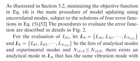
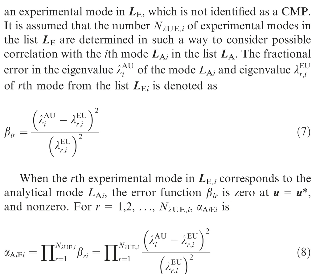
whereαis the product of errors between eigenvalue of FE mode Land experimental eigenvalues in L. αis zero when one βfunctions for r=1;2;...;Nis zero, i.e., when a mode in list Lcorrectly matches with a mode Lat u=u*. The error function Iis then defined as the sum of all αfor i=1;2;...;N:
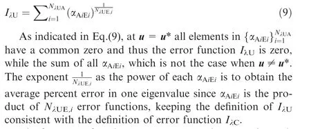
The four error functions I, I, Iand Ican be evaluated by the above analysis.At u=u*,all the error functions are zero so that the objective function F is also zero.Since F is a non-negative function, the optimization procedure achieves the global optimum at this point. Thus, by minimizing the objective function F, we can achieve the correct value u* of the unknown solution vector u.
4. Model updating with uncorrelated modes
In this section,the performance of the developed model updating method using uncorrelated modes is tested by the FE model updating of a simulated beam structure.
4.1. FE modeling of a fixed–fixed beam structure
An undamped FE model of a fixed–fixed beam structure in Fig. 3 is studied in this section. The beam geometry is 1 000 mm in length, 50 mm in width and 5 mm in height. For the beam,the modulus of elasticity E,Poisson ratio ν and density ρ are 2.0×10N/m, 0.3 and 7800 kg/m, respectively.The beam is modeled using six two-nodded beam elements(denoted by E1, E2, E3, E4, E5 and E6) as shown in Fig. 4, with lateral and axial displacement and rotation at each node as degrees of freedom. The initial FE model and its six FE components are shown in Fig.5 where different colors indicate the different material properties and boundary conditions considered to match those in the real structure.The natural frequencies and modes acquired by FE model analysis are considered as analytical/FE model data.
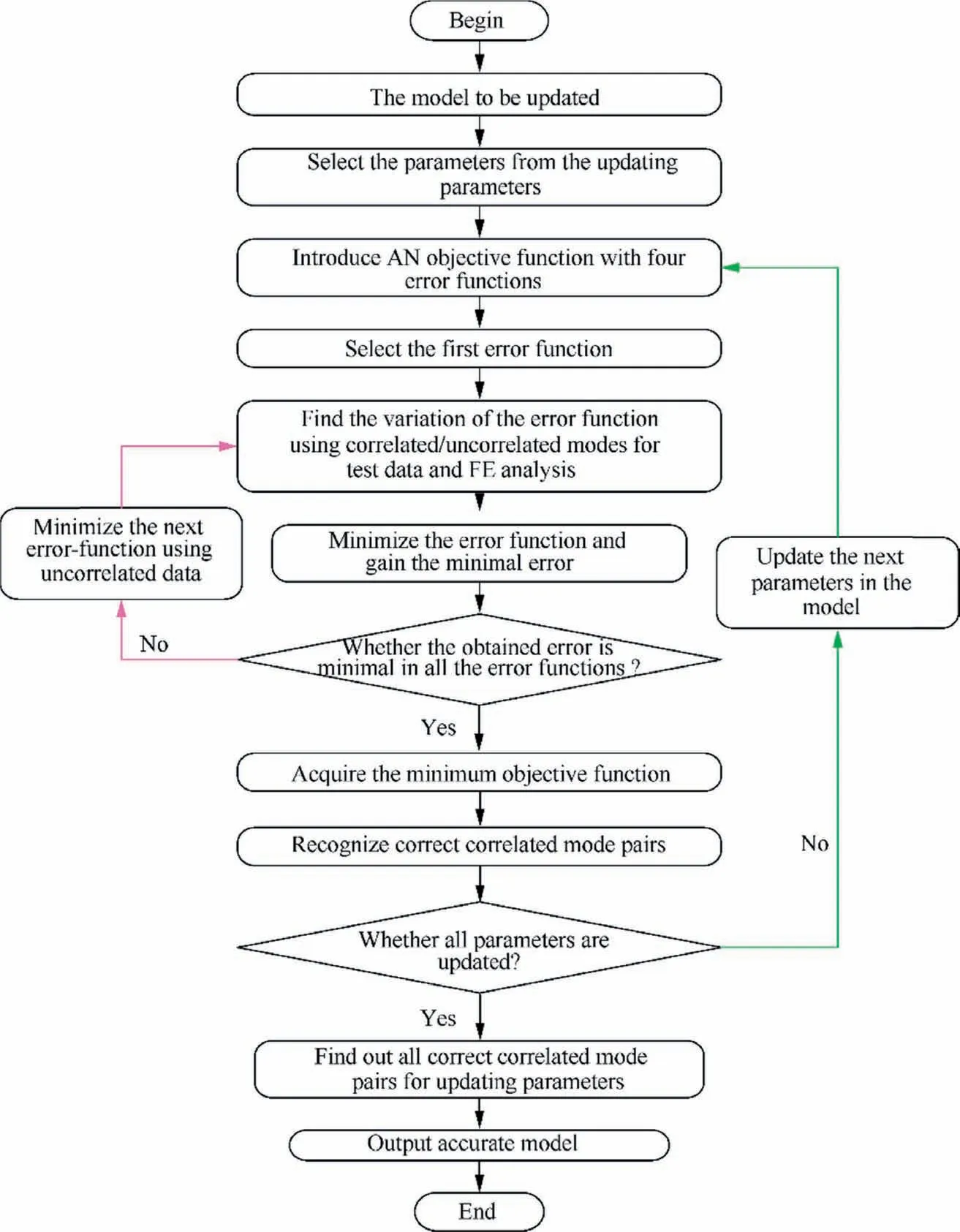
Fig. 2 The procedure of dynamic model updating with uncorrelated modes.

Fig. 3 Fixed-fixed beam structure (mm).

Fig. 4 Simulated fractions of beam structure.
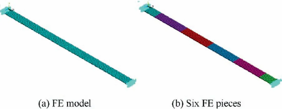
Fig. 5 FE model of beam structure.

Table 1 The updated parameters of six components between FE model and experiment.
4.2. Experiment and simulation of beam structure
The true elastic moduli of the six FE pieces as shown in Fig.4 are listed in the second line in Table 1.Known discrepancies in the third line in Table 1,in percentage with respect to the true values, are introduced in the moduli of elasticity of all six FE components, where the signs correspond to how the predicted values compare to the true values(positive or negative).Due to the limitations of performing actual experiments, we simulate the true values by performing FE analysis using the correct parameters.By completing the numerical analysis of the simulated model,the eigenvalues and eigenvectors of the model are considered as the actual experimental data,which will be used as the true values for demonstration purposes. For each component, we assign an updating parameter u, which quantifies the discrepancy between the true value (in this case, from the simulated experiment) and the predicted value (from FE analysis with erroneous parameters). The correct values of these updating parameters are tabulated in the last line of Table 1,in which the values in fractions correspond to the percentage errors in the second line.
4.3. Model updating process considering uncorrelated modes
In respect of the model updating procedure in Section 3.3, the 1st FE model eigenvalue/eigenvector is considered to be correlated with the 1st measured eigenvalue/eigenvector. However,we assume that a reliable pairing of the 2nd and 3rd FE model modes cannot be obtained.The correlation matrix is shown in Table 2,where the correct correlations for the 2nd and 3rd FE model modes are yet to be identified.
As shown in Table 2, mode pair (1A, 1E) is regarded as a CMP, while mode pairs (2A, 2E), (2A, 3E), (3A, 2E) and(3A, 3E) are considered as UMPs, because the actual correlation among them are not confirmed. According to the model updating strategy using correlated and uncorrelated modes,the initial FE model of the beam is updated by minimizing the objective function F.The constant scalar weighting factors ω,ω,ωand ωare all set to 1,i.e.,they all have equal weightings. The function F is constructed by four error functions(I,I,Iand I)which contain information on correlated and uncorrelated modes. For the updating process ofthe beam model using correlated and uncorrelated modes,the variation of F and its error functions with updating parameters are studied. Variation of error functions with the first updating parameter uis first considered by assigning the correct values of other updating parameters, i.e., u=0.5,u=0.25, u=–0.3, u=0.2 and u=0.6 as listed in Table 1. In light of correlation matrix in Table 2, the error Iin the eigenvalues of CMPs is

Table 2 Correlation of mode shapes between FE and experiment.
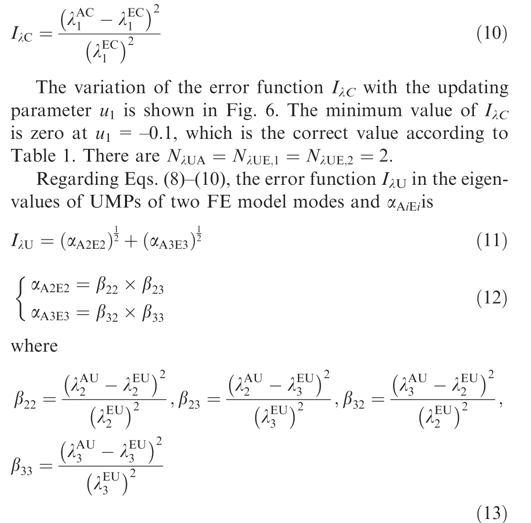
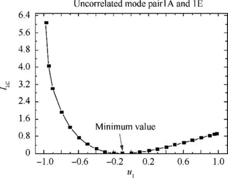
Fig. 6 Variation of the error function IλC with updating parameter u1.
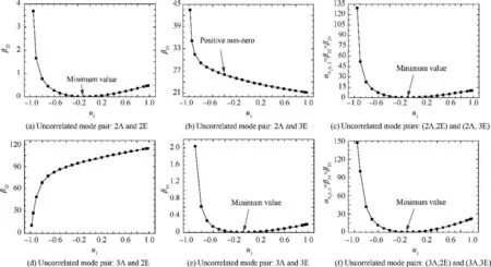
Fig. 7 Variation of the error functions to u1.
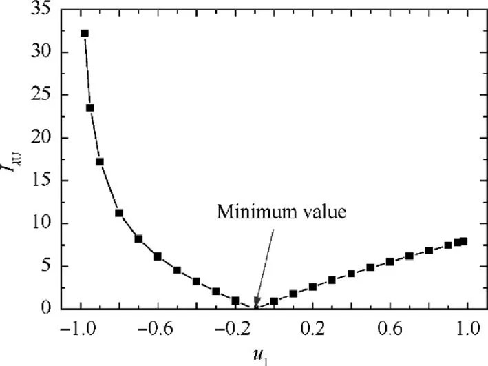
Fig. 8 Variation of error function IλU with updating parameter u1.
By evaluating β,β,βand βbased on updating of FE model with uvarying in [–1, 1], the variations of βand βare shown in Figs. 7(a)-(b). Fig. 7(c) shows the variation of the function α=β×βwith u, which is essentially the product of the functions plotted in Figs. 7(a)–(b). Similar to βand β,the variations of βand βwith uare presented in Figs. 7(d)–(e),respectively. Fig.7(f) depicts the variation of the function α=β×βto u. It is found that the function αalso has a zero at u=-0.1 and exhibits upward trends on either side of this point.
In the process of updating, the variation of the error function Iwith uis shown in Fig. 8. As shown in Fig. 8, the error function Ialso has a zero at u=–0.1 and increases on either side of this point. Similarly, Iand Ican be acquired. With the acquired error functions, the objective function F can then be computed by

The evaluating results of the objective function F is shown in Fig. 9. It can be seen that the objective function reaches its minimum value, which is zero, at u=–0.1, which is the correct value.
The above discussion shows how to find one updating parameter uin FE mode of beam structure using uncorrelated modes. Similarly, the other five parameters (u, u, u, uand u) can be updated in a similar manner. After minimizing the objective function F,the correct values of all updating parameters are
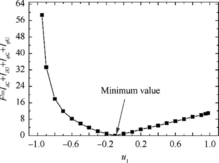
Fig.9 Variation of objective function F with parameter u1.

To further support the effectiveness of the updating technique, the comparison of the first five natural frequencies before and after updating for the experiment and FE model is shown in Table 3, regarding MAC values.
4.4. Discussions
It is illustrated in Fig.7: (A) βhas a zero and βhas a positive value at u=-0.1, because the 2nd analytical mode indeed correlates with 2nd measured mode and does not correlate with 3rd measured mode. The βdecreases with rising usince the 2nd analytical eigenvalue increases and approaches the 3rd measured eigenvalue; (B) βreaches the minimum point at u=-0.1, since the 3rd analytical and the 3rd measured modes are indeed correlated; (C) The 3rd analytical mode does not correlate with 2nd measured mode so that func-tion βin Fig.7(d)has a positive non-zero value at u=–0.1.Similar to β,βincreases with the increase of ubecause the 3rd analytical eigenvalue increases and gets further away from the 2nd measured eigenvalue; (D) α=β×βreaches zero at the correct value of the updating parameter u, since βis zero at this point. If the 2nd analytical mode correlates with 3rd measured mode, βwould have a zero at the correct value of the updating parameter u. In this case, the function α=β×βwould still have a zero at the correct value of ueven though not all component values are zero.This conclusion is very important and useful, because this property ensures that the minimization process automatically form a pair of modes which is actually correlated, i.e., the error functions A αand αA are convergent. In other words,when the correlation of FE model modes with experimental modes cannot be correctly paired, the correlated and uncorrelated modes in experimental modes with respect to analytical/FE model modes can be automatically identified by the term βin the objective function F. Therefore, model updating should be performed when the correct pairs of modes from the two sets of data are unknown.

Table 3 Experimental and FE model natural frequencies before and after updating.
As indicated in the analysis on the objective function F with parameter u, all the error functions (I, I, Iand I) in the objective function F reach zero at the correct value of u,as shown in Fig. 9. As such, F also reaches the minimum value(zero) at this point. Therefore, minimizing the non-negative objective function F can find the correct value of the updating parameter u.
As illustrated in Eq.(15),all the updating results are consistent with the data in Table 1, demonstrating the correctness and efficiency of the results acquired by handling uncorrelated modes in model updating.As revealed in Table 3,both natural frequencies and MAC values show a perfect correlation for the updated model, not only for the modes used in updating (the first three modes shown in shade) but also for those not used in updating. A MAC value of 1.0 for the 2nd and 3rd modes indicate that the proposed model updating method can automatically identify the correct CMPs.
Therefore, the proposed updating method is demonstrated to be efficient in FE model updating with both CMPs and UMPs. The upcoming section implements the hierarchical model updating of complex assembled structure,the stator casings of an aeroengine, with the assistance of parametric modeling and hierarchical thinking.
5. Hierarchical updating for stator structure (casings)
The stator system of aeroengine is formed by assembling several casings via bolted joints. The modeling and updating of the stator system involve complex geometry of joint structures,large-scale model, a large number of parameters, highnonlinearity, and strong coupling between substructures.Updating the whole model of stator system simultaneously will incur expensive computational cost and with low modeling accuracy. Additionally, the stator system (casings) of an aeroengine is a symmetrical thin-walled cylinder structure.[48–51]Modes of casings are typically complicated so that uncorrelated modes like close modes exist which might adversely affect the model updating process. In this case, available model updating techniques based on experimental test natural frequencies and mode shapes are inefficient to quantify the correlation of test modes with FE model modes. To achieve the accurate FE model of aeroengine casings,we attempt to adopt the developed HMUS to address the above issues by combining the parametric modeling of bolted joint structures and model updating of substructures by considering both correlated and uncorrelated modes.
5.1. FE modeling of an aeroengine casings
Generally,the stator system comprises four parts of intermediate casing,compound external duct,load-bearing external casing, and afterburning casing. These casings are assembled as whole stator casing system by bolt structures. The initial FE model of the casings with 49152 elements and 91485 nodes is shown in Fig. 10, in which the main installation section on the left of the casings restrains three directions and the auxiliary installation section on the right of the casing constrains one direction.The FE model is established in Workbench environment in Ansys software.
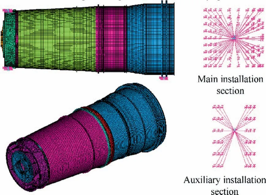
Fig. 10 Initial FE model of casings structure of an aeroengine.
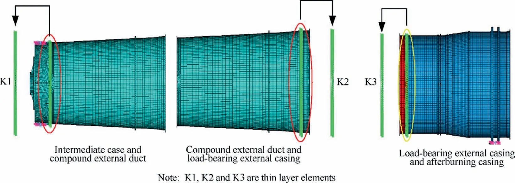
Fig. 11 Disassembling of the casings structure model.
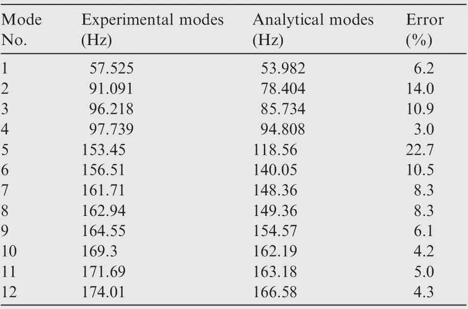
Table 4 Experimental and FE model modes of casings structure.
Following the parameterized modeling theory and spring element method,the mechanical characteristics of bolt jointed structures contacting adjacent casings are equivalently simulated by spring elements. The spring elements between intermediate casing and compound external duct, compound external duct and load-bearing external casing, and loadbearing external casing and afterburning casing, are indicated by green in Fig. 11 (similarly hereinafter).
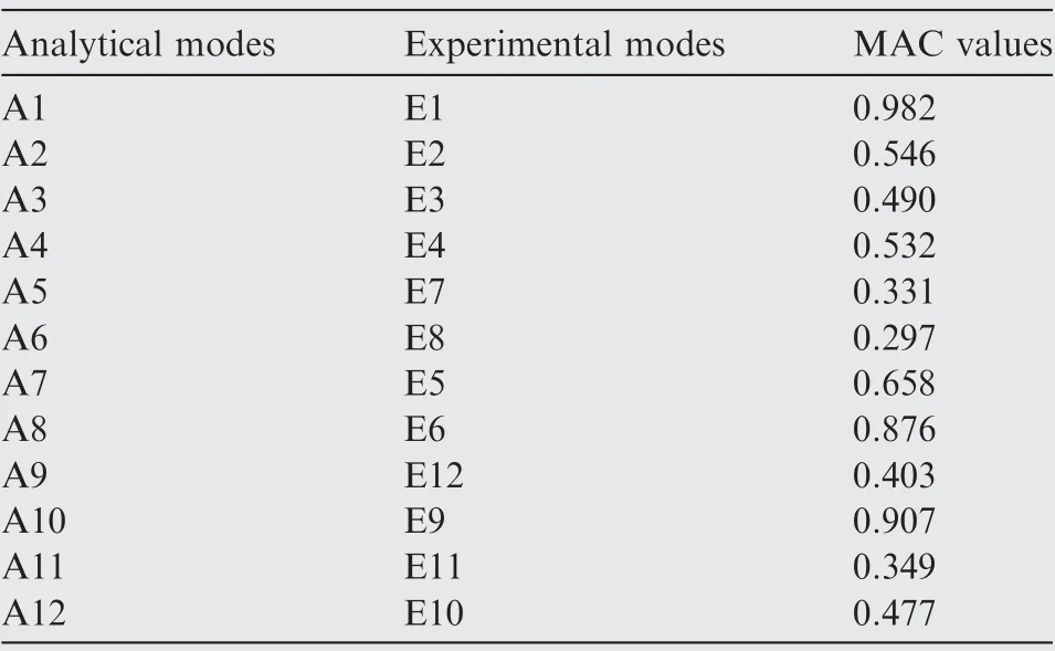
Table 6 Results of matching pairs between experimental and FE modes with MAC matrix.
5.2. Model updating using the traditional methods
In this section, the FE model updating of structural dynamics for an aeroengine stator system (casings) are investigated by using the traditional method, by relying on the MAC matrix.The three locations of bolt jointed in the initial FE model of the casings are regarded as the sources of modeling errors.In light of experimental measurements, the stiffness of thethree bolt jointed structures are K=2.3×10N/m,K=1.5×10N/m and K=1.0×10N/m, respectively.Besides, the intrinsic frequencies of stator casings system obtained from experiment are listed in Table 4.The initial stiffness of the three bolt jointed structures computed with the FE model are K=1.5×10N/m, K=1.5×10N/m and K=1.0×10N/m, respectively. From the FE model analysis, the intrinsic frequencies of stator casings system are summarized in Table 4. The MAC matrix between experimental modes and FE modes is shown in Table 5. Based on Table 5 and the traditional method without the consideration of uncorrelated modes, the maximum MAC values and modal correlation of FE modes and experimental modes are shown in Table 6.

Table 5 MAC matrix between experimental modes and FE model modes.
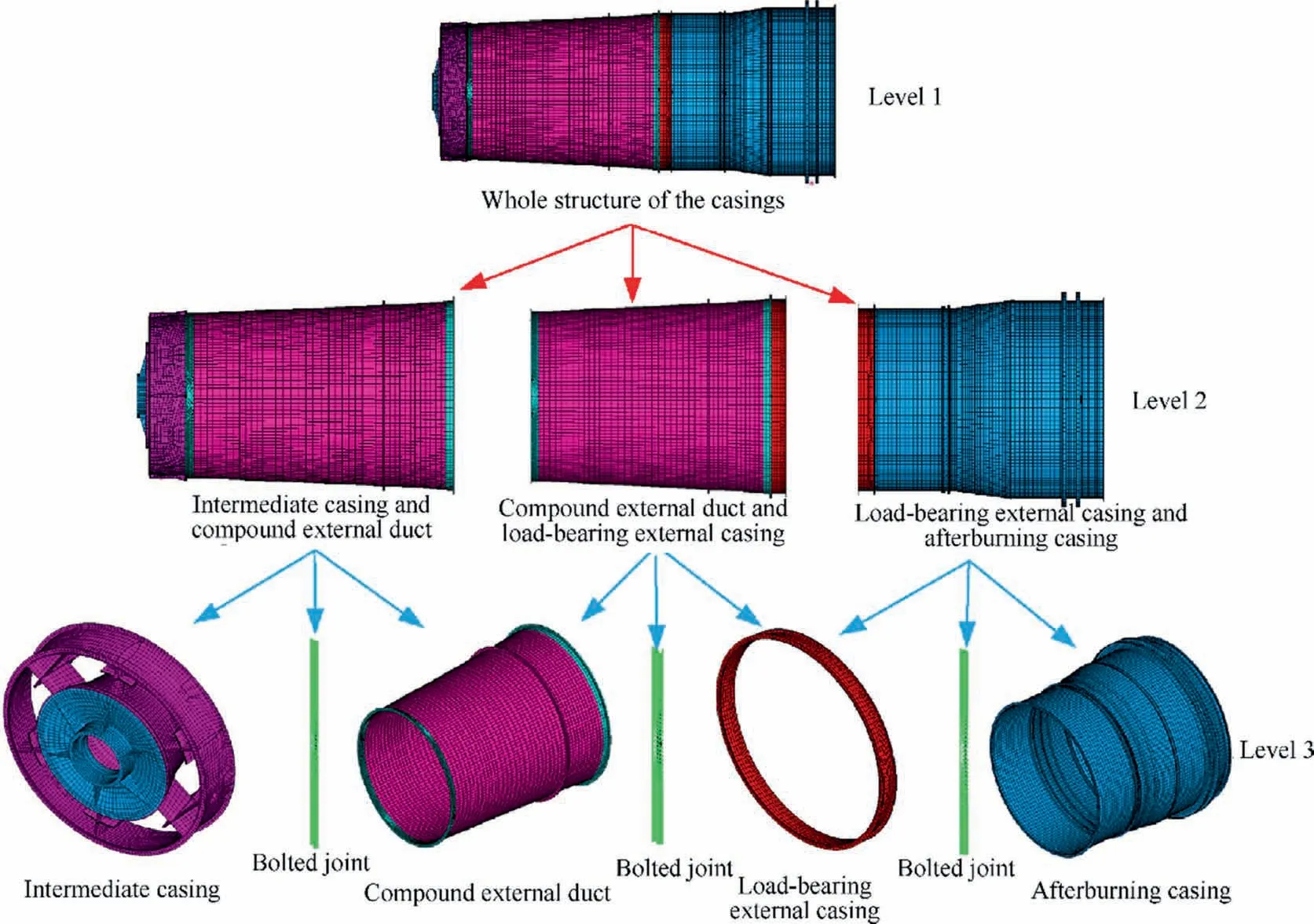
Fig. 12 Model decomposition process of the stator structure (casings).
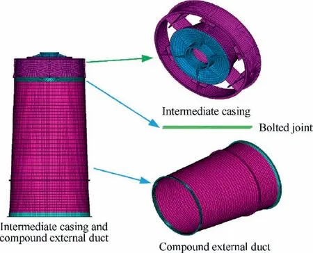
Fig. 13 Model updating procedure of Intermediate case and compound external duct.
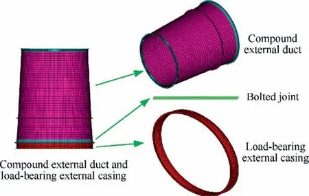
Fig.14 Model updating process of compound external duct and load-bearing external casing.
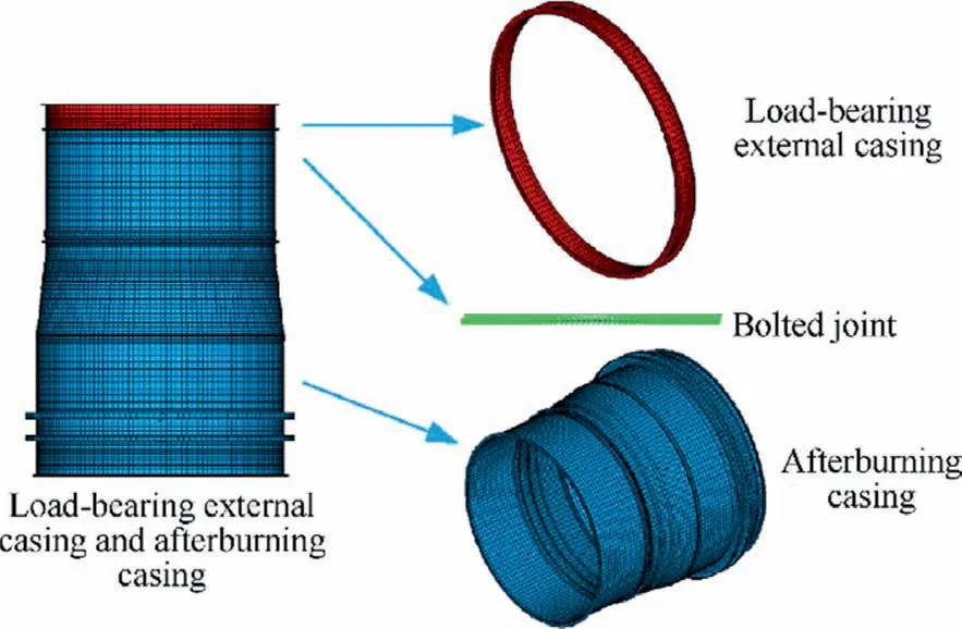
Fig. 15 Model updating procedure of load-bearing external casing and afterburning casing.
As indicated in Table 4, some errors exist between the natural frequencies of initial FE and the natural frequencies of experimental measurements with a maximum error of 22.7%for an aeroengine stator system. As revealed in Table 5, the discordance also appears between experimental vibration shapes and the corresponding FE vibration shapes. As seen from MAC values listed in Table 5, the analytical modes A5–A10 and A12 are ineffectively matched with the corresponding experimental modes based on the maximum MAC values. As demonstrated in Table 5, the analytical modes of the initial FE model from A3 to A12 have two or more potentially correlated experimental modes. These results reveal that the experimental modes of the casings are indeed not always consistent with the corresponding FE modes, so that the mechanical characteristics of the initial FE model are unable to accurately reflect the actual dynamical characteristics of the stator casings. Therefore, it is urgent to update the initial FE model by using dynamical test data to improve the accuracy of FE models and thereby make the mechanical characteristics of the FE model be more consistent with those of the stator casings.
Table 5 shows that only the first two modes can be accurately matched between the experimental and analytical modes, and therefore the CMPs of the first two orders of modes can be correctly determined.However,it is not yet possible to accurately recognize the correlation of other orders of modes. As such, it is one alternative for the dynamical FE model updating of the stator casings with the uncorrelated modes to employ the developed updating technique in this paper to update the dynamical FE model of the casings, by using the information on the uncorrelated modes.In addition,it is also revealed that some adjacent orders of intrinsic frequencies or mode shapes are very close, namely close modes,because the stator system is a typical symmetrical thin-walled cylinder structure which is complex and large-scale that the mode shapes are very complicated. Therefore, it is difficult toprecisely match an experimental mode and the corresponding FE mode. Although the large-scale and complex structure of the stator system may be updated based on the proposed method, the updating process must be tedious so that the updating efficiency is unacceptable. Therefore, the model updating of the stator system should be performed by HMUS with updating technique using uncorrelated modes. The updated results will be presented in Section 5.4.
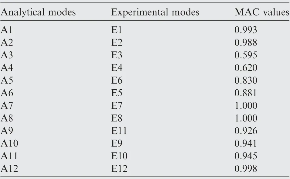
Table 8 Maximum MAC values of FE modes and experimental modes with traditional method.
5.3. FE model updating of the casings (substructures) with uncorrelated modes
In light of the hierarchical model updating concept, the stator system(casings) of an aeroengine is divided into multiple simple substructures or components by three layers as shown in Fig. 12.
Based on test data, the intermediate casing, compound external duct, load-bearing external casing and afterburning casing are updated separately, to achieve a more accurate FE model for each substructure. Next, intermediate casing and compound external duct, compound external duct and loadbearing external casing as well as load-bearing external casing and afterburning casing are analyzed as connected structures by bolted joints. Similarly, the bolted joint structures are updated by using experimental test data to gain their accurateFE models. Finally, the high-fidelity FE model of the stator casings of aeroengine is obtained by integrating the four updated casings.

Table 7 MAC matrix of experimental and FE model modes with traditional method.
The FE model updating of intermediate casing and compound external duct, compound external duct and loadbearing external casing, and load-bearing external casing and afterburning casing using uncorrelated modes on level 2 in Fig. 12 are shown in Figs. 13–15.
For intermediate casing and compound external duct, the MAC values of FE modes and experimental modes are listedin Table 7 based on FE model analysis and experimental measurement.Similarly, as our discussion in Section 5.2, the maximum MAC values and modal correlation of FE modes and experimental modes are shown in Table 8.

Table 9 Model updating results of intermediate case and compound external duct using uncorrelated modes.

Table 10 Model updating results of compound external duct and load-bearing external casing using uncorrelated modes.

Table 11 Model updating results of load-bearing external casing and afterburning casing.

Table 12 Updating results of whole FE model of aeroengine casings.
As shown in Table 8, it is inefficient for the traditional method to match FE model modes and the corresponding experimental modes, because uncorrelated modes between experiment and FE model just like close modes are not effectively processed in FE model updating. Based on the data of uncorrelated modes in Table 7, the proposed model updating technique using uncorrelated modes is adopted to update the FE model of intermediate casing and compound external duct.The updated results are shown in Table 9.
As indicated in Table 9,all FE model modes after updating can now be accurately matched to experimental modes,because the match errors on natural frequency is rather small with 0.39%in the maximum error and 0.06%in the minimum error. In other words, the correct CMPs between FE modes and measured modes can be identified for the FE model of intermediate casing and compound external duct.These results demonstrate that the proposed model updating using uncorrelated modes is suitable to identify correct CMPs in dynamic model updating of complex structures with uncorrelated modes. Following the same model updating approach, the FE model updating of compound external duct and loadbearing external casing as well as load-bearing external casing and afterburning casing are performed.The results are listed in Table 10 and Table 11, respectively.
As revealed in Tables 9–11,the results after updating by the proposed updating technology are accurate and all FE model modes can be accurately matched with test modes for all casings with bolted joint structures of aeroengine stator system,with notable error reduction from before updating, specially from 40.63%to 1.83%for 8th mode in Table 11.It is demonstrated again that the proposed mode updating strategy is workable in the model updating of casing structures
5.4. Model updating of stator system
By the updated FE models of the whole casings with the developed HMUS, the results are summarized in Table 12.
As shown in Table 12, the modes of FE model of the casings have large errors from experimental modes before updating. The maximum error is 22.7% and the minimum one is 3%, which indicates that the FE model of the stator system is unacceptable and cannot accurately represent the real stator structure, although the models of substructures (casings) are accurate after updating. Therefore, the whole model of stator system still needs to be updated to minimize the deviation from the true assembled structure. After updating by HMUS, the accuracy of the whole FE model notably improves for all modes,basically consistent with the corresponding experimental modes,because the errors are reduced largely.For instance,22.7% in the error of 5th mode before updating is reduced to 4.07% after updating. Here, we have successfully demonstrated that the HMUS is efficient and accurate in the model updating of complex assembled structures, such as the stator system (casings) of gas turbine engine, with uncorrelated modes.
6. Conclusions
(1) A hierarchical model updating strategy (HMUS)is proposed for dynamic model updating of complex assembled structure with uncorrelated modes and bolted joints,by fusing hierarchical concept,parametric modeling method and model updating technique using uncorrelated modes.
(2) The HMUS can effectively handle uncorrelated modes and precisely identify automatically the correct CMPs(uncorrelated mode pairs) in model updating by introducing an objective function with four error indicators,which is helpful to address the difficulties of identifying correct CMPs in structural dynamic model updating in complex mechanical systems.
(3) the proposed HMUS accurately updates the FE model of the complex assembled casings with large-scale model, complex geometry, numerous parameters and high-nonlinearity, by decomposing it into multiple simple substructures with fewer parameters and lownonlinearity under different layers, validating the effectiveness and feasibility of HMUS by ensuring a high accuracy of the updated FE model. Besides, the model updating technique using uncorrelated modes is further demonstrated to be effective in processing uncorrelated modes, including close modes. Therefore, the HMUS is capable of building a high-fidelity FE model of aeroengine casings (stator system) and to apply the updated model to dynamic analysis and aeroengine health monitoring in future work. Lastly, parametric modeling is also an efficient tool in model updating of structures with complex geometry, by simulating mechanical characteristics of bolted joints in aeroengine stator casings.
(4) The works in this paper offer a useful insight into the challenges in updating FE models in a complex structure and how a novel model updating strategy can help provide accurate and reliable FE modeling of any complex structures, which are not limited to aeroengine stator casings.Such a development can help reduce the computational time, costs, and manpower required to perform analysis and design-based model of complex structures.
The authors declare that they have no known competing financial interests or personal relationships that could have appeared to influence the work reported in this paper.
This study was co-supported by National Natural Science Foundation of China (No. 51975124), Shanghai International Cooperation Project of One Belt and One Road of China(No.20110741700) and Major Research Special Project of Aeroengine and Gas Turbine of China (No. J2019-IV-0016).
 Chinese Journal of Aeronautics2022年3期
- Chinese Journal of Aeronautics的其它文章
- Film cooling performance and flow structure of single-hole and double-holes with swirling jet
- Lock-in phenomenon of tip clearance flow and its influence on aerodynamic damping under specified vibration on an axial transonic compressor rotor
- Solid rocket propulsion technology for de-orbiting spacecraft
- Bioinspired polarized light compass in moonlit sky for heading determination based on probability density estimation
- Effects of sweep angles on turbulent separation behaviors induced by blunt fin
- Design and analysis of a novel hinged boom based on cable drive
