Parameter study on lateral moments of banked wings in ground effect
Jingfeng XIE, Lei SONG, Jun HUANG, Jingcheng FU
School of Aeronautics Science and Engineering, Beihang University, Beijing 100083, China
KEYWORDS Angle of attack;CFD;Ground effect;Lateral moments
Abstract Ground effect dramatically improves the performance of the Wing-in-Ground (WIG)vehicles near the ground. However, making coordinate turnings in ground effect zone may raise complexity in flight control. The Angle of Attack (AOA) and height are believed to be important factors. To find the impact of these factors, three straight rectangular wings with different aspect ratios are simulated via CFD approach. The results show that in normal situations, the rolling moment tends to level the wing but less effective with the decreasing AOA and changes its direction when the AOA is less than a height dependent value. The yaw moment exhibits complex behavior because two different effects generate oppose moments. The rolling moment coefficient is more influenced by the ground if a wing has larger Aspect Ratio (AR) and works at low to medium AOA.The yawing coefficient is always more influenced if the wing has larger AR regardless AOAs.These findings can provide basic guidance for the design of control system and enable aircraft designers to reshape the crafts to avoid or utilize this effect.
1. Introduction
A ground effect appears when an aircraft works within a small clearance from the ground, in which the aerodynamics and flow physics are different from those in a free stream because the air flow is bent parallel to the ground.The ground effect on fixed wing crafts usually has a favorable effect on the lift-todrag ratio.Wing-in-Ground(WIG)crafts,which are generally regarded as promising transportation,are designed to work near the ground or water with extraordinary aerodynamic efficiency.. If the left and right halves of an aircraft are at different heights, which is usually a result of a bank angle, as shown in Fig.1,then the aircraft will experience an asymmetric ground effect. This effect usually occurs when a WIG craft makes a coordinate turningor a conventional aircraft landing with a bank angle.Since the aerodynamics of the left and right sides are no longer symmetric, the wing will generate additional roll and yaw moments. These forces and moments have a considerable impact on aircraft movements.
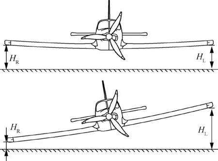
Fig.1 Height difference between left and right wing due to bank angle.
In linearized model of the aircraft in the ground effect, the coefficients of the bank angle(Cand C)are essential.Some researchers had pointed out that rolling and yawing moments are highly coupled with the AOA in an asymmetric ground effect, and it is necessary to verify the relationship between them.If the details of the aerodynamics of a banked wing in ground effect can be described, then the dynamic characteristics of aircrafts near the ground, such as degree of freedom,can be determined,which benefits simulation accuracy and will have great value in control system and aircrafts design.
To date, research on asymmetric ground effects has been quite limited,but fortunately,there have been numerous studies of conventional ground effects.The study of ground effects can be divided into many branches according to different research priorities. Based on the motion of an aircraft, the ground effect is divided into a static ground effect and a dynamic ground effect.Based on an increase or a decrease in the lift,the static ground effect can be divided into a positive ground effect,which increases the lift,and becomes a negative ground effect by decreasing the lift. Based on the aerodynamics, ground effect research can be divided into 2 branches: the Chord Dominated Ground Effect (CDGE), which focuses on airfoils in the ground effect,and the Span Dominated Ground Effect (SDGE), which focuses on how the ground influences finite wings.
Regardless of the branch of the ground effect, most early studies of the image vortex model were initiated by Wieselsberger,still a common model to this day. The image vortex model provides an analytical method to depict the flow field near an airfoil or a finite wing. Itiro and Tomotica provided the aerodynamics of an airfoil within the ground effect height with the image vortex method and depicted the flow with a conformal transformation.More accurate results were acquired when Computational Fluid Dynamics(CFD)became popular.For example, in recent years, Qu and other researchers have revealed that in the CDGE, the Angle of Attack(AOA) vs the height plane can be divided into 3 regions by 2 zero-lift-increment lines: Region 1 of the negative ground effect with a negative AOA, Region 2 of the positive ground effect with a positive AOA, and Region 3 of the negative ground effect with a positive AOA.Different regions have different flow physics. Region 1 is dominated by the Venturi effect,Region 2 is influenced by both the Venturi effect and the efficient AOA decrease effect,and Region 3 is dominated by the efficient AOA decrease effect and flow separation.. For the SDGE, with the application of CFD,recent studies have demonstrated that the wingtip vortices change into an elliptical shape and the vortex cores are reflected by the ground..
To our knowledge, there have been only a few papers to date that have investigated the asymmetric ground effect.Kumer explored the aerodynamic character of several wings in ground effect in a wind tunnel,including rolling and yawing cases.The characteristics of the force and moment on the wing were examined, and aerodynamic data was obtained.Jia et al. conducted a numerical study of a rectangular and delta wing versus the bank angle, in which the banked wings generate a righting rolling moment and an adverse yaw moment, and both moments increase nonlinearly with the bank angle.Moreover, banked wings also generate slightly more lift than horizontal wings.
To obtain more detailed insight on aerodynamic of banked wings in static ground effect, including the magnitude of the lateral moments,the relationship between the lateral moments and AOA, and how they change with height, the work starts from a simple case. Three straight rectangular wings with Aspect Ratios (ARs) of 5, 6, and 7 are calculated via the CFD method. The studied height ranges from h/c=0.5 to h/c=2, and the AOA ranges from α= -4° to α=16°.The forces and moments, along with the lift coefficent Cdistribution obtained by the CFD method. The influence factors such as the height, AOA and AR are summarized.
2. CFD method and validation
2.1. Problem definition
Three banked, straight, and rectangular wings of AR=5, 6,and 7 are simulated via the CFD approach.All the wings have a uniform airfoil (NACA23012). The wing chord is 10 in(0.254 m), and the airspeed is 80 mph (35.76 m/s). The Reynolds number is approximately 6.2×10. In previous studies,the dimensionless height was defined as h/c if the wing were in CDGE, or h/b if the wing was in SDGE. Alexander pointed out that the CDGE dominates when h/c<0.2, while SDGE dominates when h/c>1.In this paper, the analyzed minimum ride height is 0.5c, and the left wingtip is even lower,so CDGE cannot be ignored. The dimensionless height is defined as h/c. According to previous papers, the ride height also has no unified definition. In this paper, h is defined as the distance from the 0.25c point of the central chord to the ground. The coordinate system involved in this paper is the wind axis, i.e., the X-axis points backward, with the same direction of V, the Y-axis is rightwards along the span, Zaxis points upwards and forms a right-handed Cartesian coordinate system with the X and Y axes. The definition of the coordinate system is shown in Fig. 2.
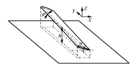
Fig. 2 Problem definition and coordinate system.
Simulated heights are h/c=0.5, 0.7, 1, 1.5, 2, and infinity,and AOA ranges from α= -4°to α=16°.The bank angle is defined as the angle at which the wing rotates around the X+axis. In this paper, the simulated bank angles are φ=0°and φ=5°, so the left half of the wing is lower, and for wing AR=5, there is an additional state of φ=7.012°. A total number of 209 working conditions were simulated.
2.2. Numerical method
The CFD method is widely used in ground effect analysis and has proved to be a reliable tool.In this paper,the computation is performed with the finite-volume method. The incompressible Reynolds-Averaged Navier–Stokes (RANS) equations and Shear Stress Transfer (SST) k-ω turbulence model are solved in all cases. A second-order upwind scheme is adopted for the diffusion and convection terms. The SIMPLEC algorithm is used to deal with the coupling of the velocity and pressure. The floor is a moving wall and has the same velocity as the mainstream.
An H-shaped multiblock mesh is employed in the computation,and both the wing and the ground have a refined boundary layer. The wingtip mesh is also refined to better simulate the wingtip flow field.The total number of elements is approximately 3.5×10.
2.3. Validation of numerical method
The grid independence of the solution is verified by simulating a wing at α=8°, h/c=0.5, and φ=0°. Since enhanced wall treatment is adopted,the boundary layer grid height is approximately y=1. The results are summarized in Table 1. Both medium- and high-density grids provide satisfying results for the lift and drag;however,medium-density grids cost less time.Therefore, y≈1 is employed in this study.
The accuracy of the method is confirmed by the simulation results and experimental results from the work of Recant.The straight and rectangular wing with AR=6, which has a NACA23012 airfoil, is calculated under the condition of V=35.76 m/s, h/c=0.5, the AOA ranges from-4° to 16°,and the height is h/c=0.5 and infinity. Note that the work of Recant is so early (paper published in 1939) that the height definition and test method are slightly different from those currently used(the height is defined as the distance from the projection of the midpoint of the quarter line on the lower surface of the wing to the ground. The wind tunnel wall and the floor are static.). The simulation cases adopted the settings of the experiment of Recant. The comparison is shown in Fig. 3.The lift difference between the simulation results and experiment is approximately 0.5% when α<12°. The simulation agrees well with the experiment, and the slightly nonlinear behavior of the lift curve is successfully predicted. However,at α=16°, the lift is overpredicted due to the delayed prediction of the separated flow.The reason can be either the error insolving viscosity in the boundary layer or the insufficient grid density at the separated flow region,and it is difficult to determine which one has the greatest impact. Generally, flow separation is difficult to precisely predict. Since the detailed analysis uses only the result within-4°<α<12° and this paper does not focus on separated flow,the effect of the overestimation is small.

Table 1 Grid independence confirmation.
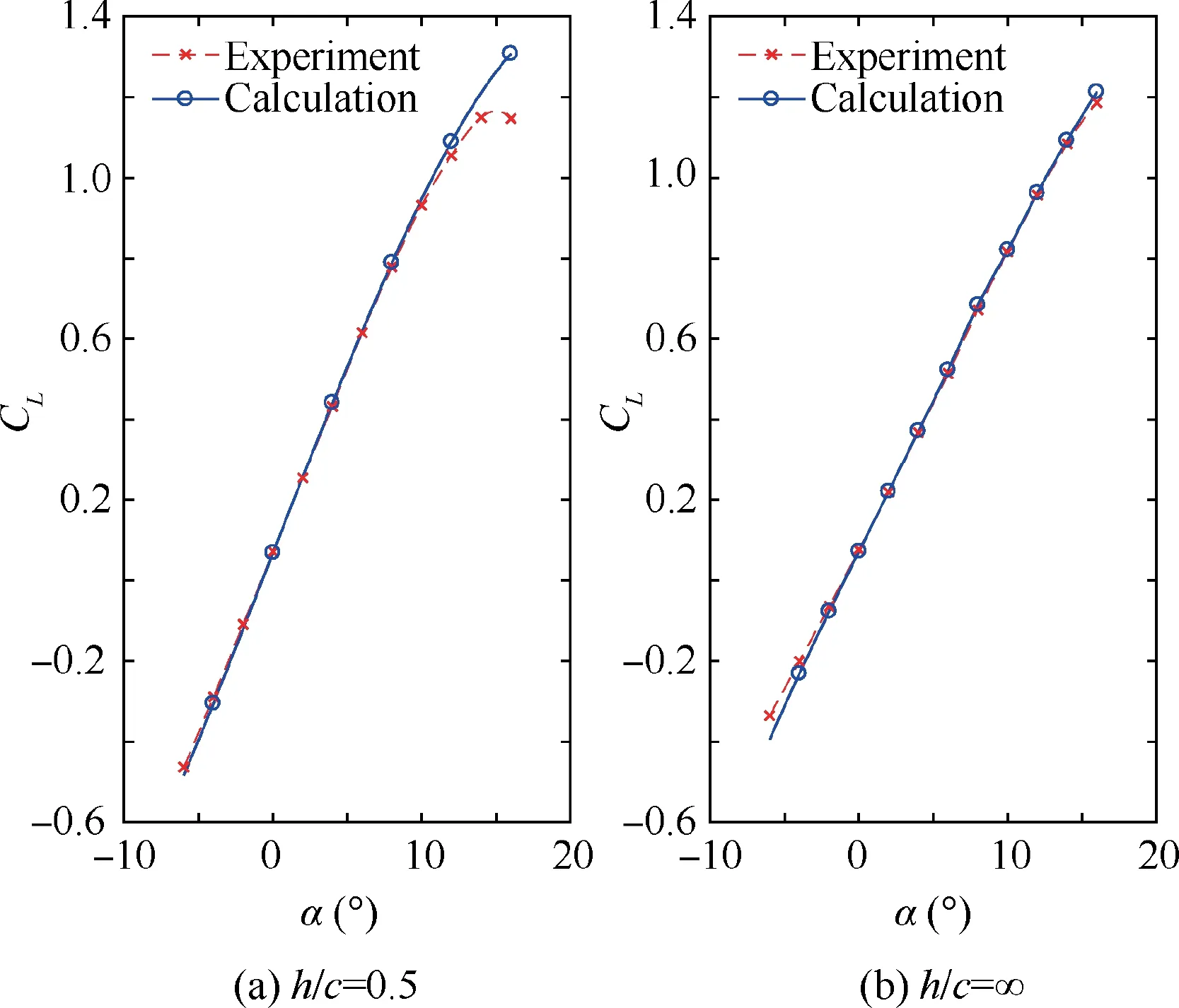
Fig. 3 Comparison of calculated result and experiment.
3. CFD results and discussion
3.1. Rolling moment
3.1.1. Relationship between rolling moment and longitude parameters
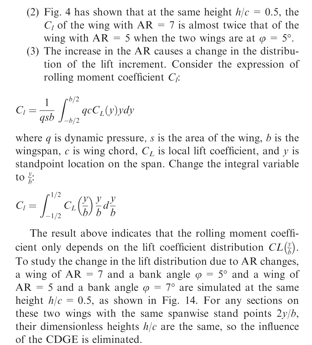
Taking the wing of AR=7 as an example,the contour of rolling moment coefficient Cas a function of height and the AOA is shown in Fig. 4. The red stars in the contour represent the calculated point,while other points are obtained by interpolation or extrapolation. Because the wing and the ground will interfere, an AOA greater than 12° of h/c=0.5 is not calculated.
A zero rolling moment curve, which lies approximately at α= -1° to α=1°, divides the AOA vs height plane into 2 regions. The trend of the rolling moment coefficient is that the larger the AOA is, the larger the rolling moment is, and vice versa. For example, the minimum Cof the wing of AR=7 appears at heights h/c=0.5 and α=10°, which can reach approximately-0.0194.The bank angle is positive,so the rolling moment tends to level the wing, i.e., a ‘‘righting moment”. For a general aviation aircraft, the aileron control derivative (δC) is approximately 0.001 per degree, and the maximum deflection angle of the aileron is approximately 20°.The rolling moment caused by the ground effect is almost the same as the maximum control moment of the aileron,so it will be difficult for an aircraft to maintain the bank angle with the aileron in this state. However, the rolling moment decreases rapidly as the height increases. At h/c=1, the Cof α=10° is only approximately 0.004. The slope of the rolling moment vs AOA (C) is related to the dimensionless height. The lower the height is, the greater the slope is.
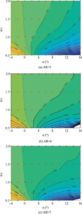
Fig. 4 Cl vs AOA and height contour of wings at φ=5°.
The rolling moment is mainly caused by the asymmetry of the lift distribution. Taking the wing of AR=5 as an example, observe the surface static pressure contour with banking φ=5° at α=8° and h/c=0.5 (Fig. 5), it can be seen that the pressure distribution on the left and right surfaces is obviously different. The lift coefficient Cvs 2y/b figure of α= -2°,6°,and 12°shows that the Cof the left half,which has a negative 2y/b,is larger than that of the right half(Fig.6).This difference comes from both the SDGE and CDGE.
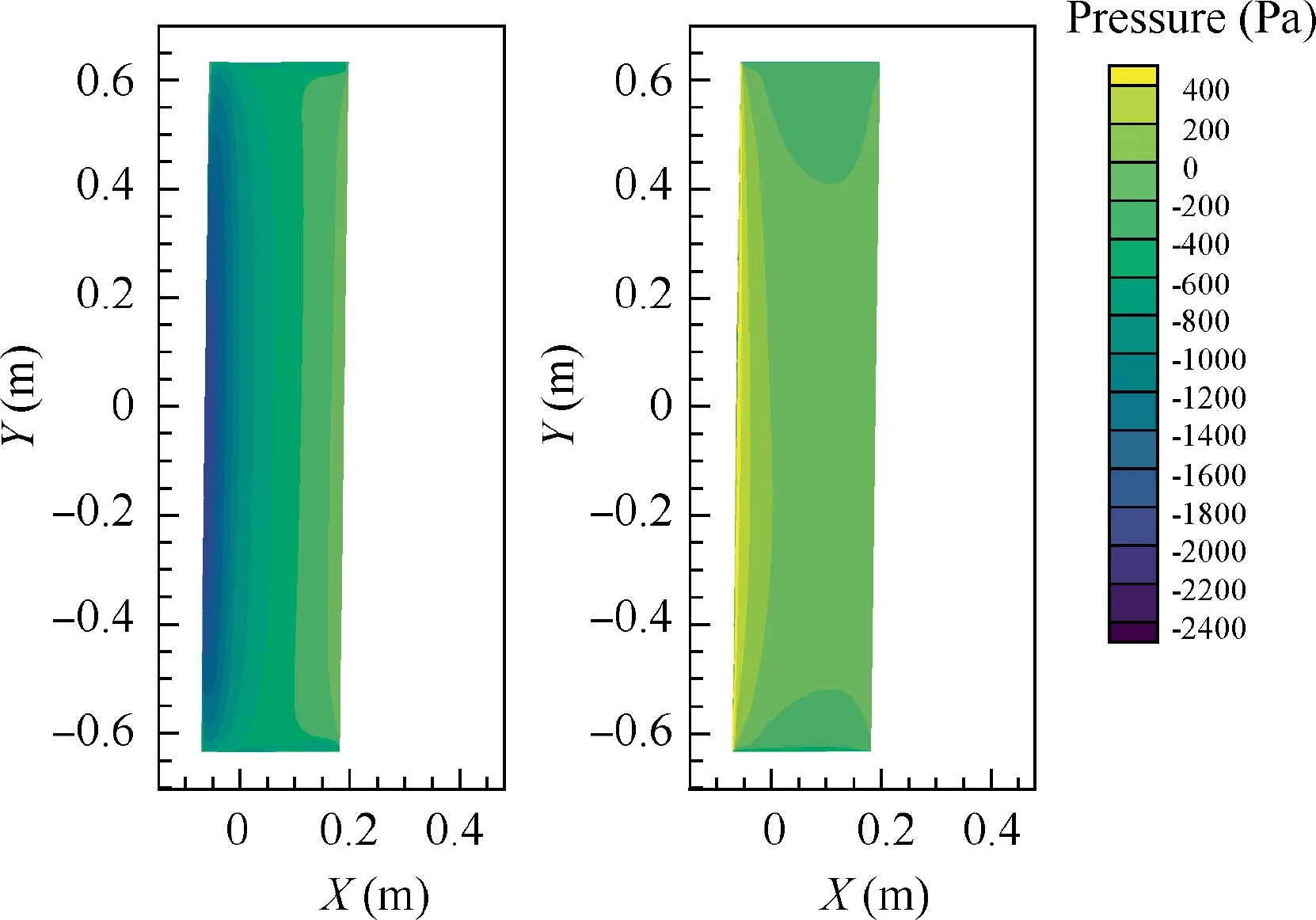
Fig. 5 Upper (left) and lower (right) surface static pressure contours of wing with AR=5 at h/c=0.5, φ=5°, and α=8°.
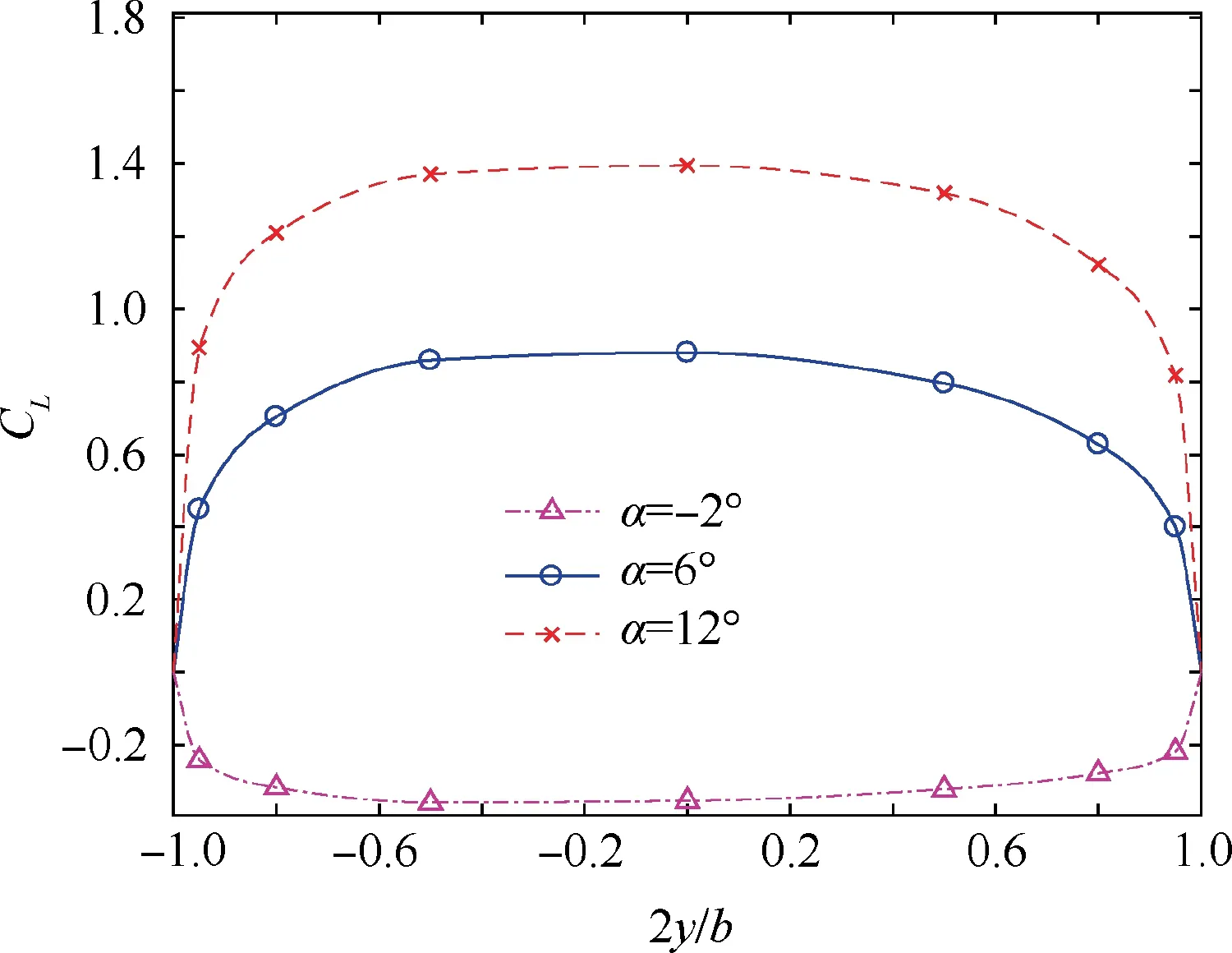
Fig. 6 Wing lift distribution of wing with AR=7 at h/c=0.5 and φ=5°.
The CDGE has been well explained in the works of Kumerand Qu et al.There are two effects of the CDGE when there is no flow separation involved. The first is that the ground effect will cause the effective AOA to change, which can be explained by the image vortex theory. A typical image vortex model for positive ground effect is shown in Fig.7.The image vortex may increase or decrease the lift, and is due to the dimensionless height and AOA as Tani stated.The second is that the flow path formed by the lower surface of the airfoil and the ground can produce a significant Venturi effect,which in most cases causes the pressure at the bottom of the airfoil to rise at a positive AOA, and vice versa.
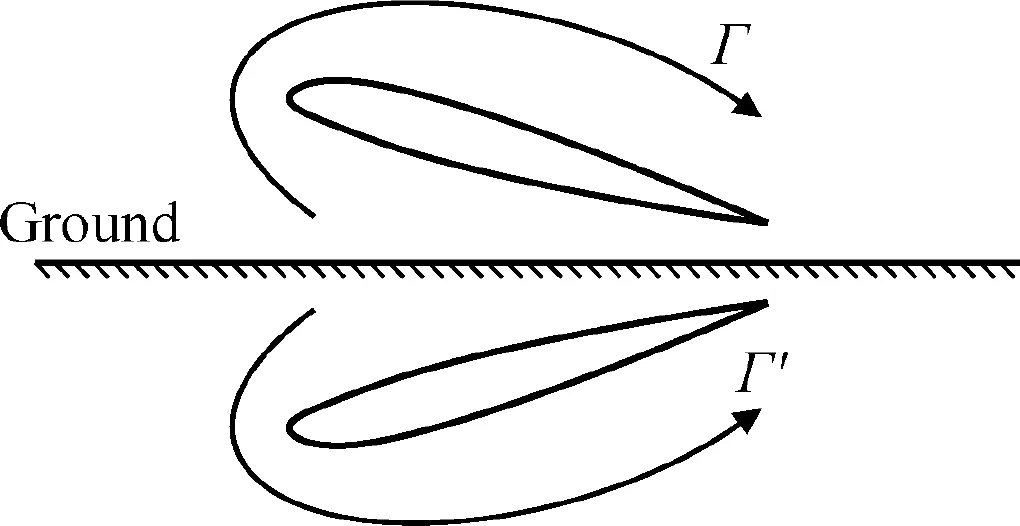
Fig. 7 Image vortex of an airfoil.
For banked wings, due to the difference in the height from the left and right sides of the wings,the CDGE of each section is different. Therefore, although the geometric AOA is the same for each section, the lift is not equal. For common situations in a normal flight, the wing works at α=4°~10°, and generates a positive lift. Fig. 8 shows the Cfigures of the sections of 2y/b=±0.5 and±0.8 at h/c=0.5 and α=8°.Take section 2y/b=±0.8 as example, on the one hand, the suction peak on the Ccurve of the left half (C= -1.9) is higher than that of the right half (C= -1.7), and the stationary point on the lower surface of the left half moves slightly to the trailing edge (from x/c≈0.01 to x/c≈0.02). These two values indicate that the effective AOA of the left half is larger than the right. On the other hand, the maximum Cof the lower surface on the left half (C=0.6) is higher than that of the right half (C=0.5), indicating that the Venturi effect also increases the lift here. The left half is more influenced by the ground, and the increase in lift is larger, so the CDGE generates a‘‘righting”moment,helping the wing to return to a level state.
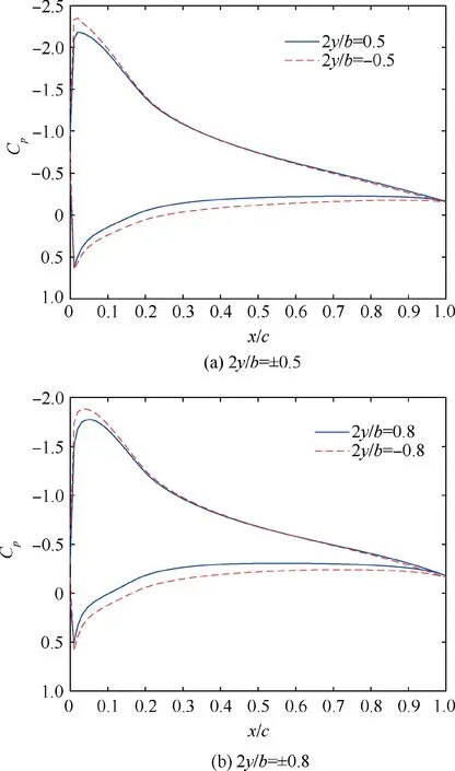
Fig. 8 Cp curves of sections (Wing AR=5, h/c=0.5, φ=5°,and α=8°).
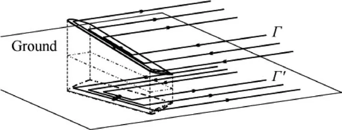
Fig. 9 Image vertex of a wing.
For the SDGE,the classical image vortex theory combined with the lifting-line theory can provide a satisfactory explanation. The image vortex and the horseshoe vortex of the wing are symmetrical about the ground, with the same size and the opposite direction,as shown in Fig.9.In conventional situations,the wing generates a positive lift,and the image vortex weakens the downwash of the wing, resulting in a rise in the effective AOA. The lift curve slope rises, so the lift can be increased,and the induced drag,which also depends on downwash, can be reduced. The influence of this effect depends on height and increases as height decreases. For a banked wing,the increase in the lift curve slope on the lower side is larger,and the lift increase is therefore larger,so the SDGE also provides a righting moment.Summarizing the above, for most situations the rolling moment tends to level the wing, and its magnitude increases as the AOA increases or the height decreases. Both CDGE and SDGE contribute to rolling moment.However,three phenomena should also be considered. (A) The rolling moment can be negative; that is, the ground effect does not necessarily generate a righting moment, and it may also be a ‘‘divergent moment”; that is, the rolling angle will increase. (B) At a certain height,with an increase in the AOA,the contours become denser first and then thinner; that is, the derivative of Cvs AOA (C) increases first and then decreases as the AOA increases. (C) The zero-rolling-moment AOA does not coincide with zero-lift-AOA and increases as the height decreases.The following texts will discuss these phenomena in detail.
3.1.2. Discussion continued
(1) Negative effects of ground effects on the rolling moment.As explained earlier, the rolling moment is caused by an uneven lift distribution.If the lower side generates more lift increase, then the rolling moment tends to level the wing.However, if the wing produces a negative lift, then the situation will be different.
For the SDGE, the lift increases as a result of the increase in the lift curve slope. If the lift is negative, then increasing the lift curve slope will cause the lift to decrease further.Therefore,in the case of a negative lift,the higher and lower sides have different effective AOAs. The lower side generates more negative lift,and a divergent moment will be generated; that is, the bank angle will be increased.
For the CDGE, the flow path formed by the lower surface of the airfoil and the ground is an expansion channel when the AOA is negative, which can produce a significant Venturi effect, causing the pressure on the lower surface of the wing to drop. The Venturi effect is more effective as the dimensionless height h/c decreases. Therefore, the CDGE also results in a divergent moment.
The divergent moment can be very large.Back to Fig.4,the maximum Cof wing of AR=7 appears at h/c=0.5,α= -4°,which approximately C=0.017.A general aviation aircraft in this situation will need more than 17° of aileron deflection to level its wing,which causes much more difficulties for pilot to handle.
(2) The derivative of the Cto the AOA first increases and then decreases.Fig.10 shows that the section lift difference between the left and right sides of the wing generates a rolling moment. Looking closely at the curve, it can be seen that unlike the free flow case, where the lift curve of wing sections is a straight line until the section stalled, in the ground effect case,it is slightly bent.The bending of the lift curve is attributed to the loss of upper surface suction,which is revealed in the work of Ahmed et al.The lift curves on both sides are slightly bent but not equally bent.The one on the lower side is more curved,which makes the difference in lift between the two sections change. The lift differences of two pairs of sections,2y/b=±0.5 and±0.8,are shown in Fig.11.Take section 2y/b=±0.8 as example,the Cdifference reaches a maximum of 0.089 at α=8°but reduces to 0.064 at α=14°. The rolling moment behaves in the same way, making the derivative of the Cto the AOA first increase and then decrease.
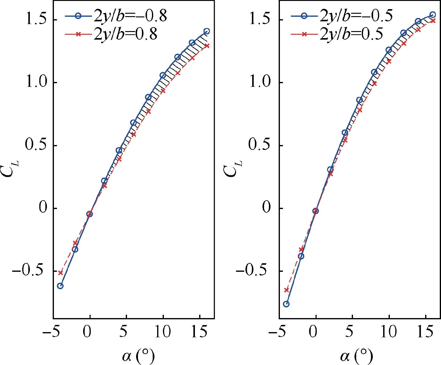
Fig. 10 CL vs AOA of sections (Wing AR=5, h/c=0.7, and φ=5°. The shade represents the CL difference).
(3) The zero-lift-AOA curve and the zero-rolling-moment curve do not coincide. Fig. 12 shows the Cincrement contour on the height vs. the AOA plane, and the zero rolling moment curve is shown by the red dashed line.Regardless of the height,the zero-moment AOA is always larger than the zero-lift AOA, and the lower the height is,the larger the difference is between them.Taking the wing with AR=6 and φ=5°as example,the zero-lift-AOA at h/c=2 is approximately α= -1°, and zero-rollingmoment AOA is approximately α= -0.8°. At h/c=0.5, the zero-lift-AOA is approximately α= -0.6°,and zero-rolling-moment AOA is approximately α=1.3°.The rolling moment is zero when both sides of the wing have equal lift. A figure of the Cof the left and right half sides of the wing is shown in Fig. 13. It is easy to see that the rolling moment is zero at the intersection of the two curves (α=1.3°), and the lift is zero when the sum of the two sides is zero (α= -0.6°). On the one hand, as the wing approaches the ground,the zero-lift AOA of the wing sections is increased due to the CDGE.The lower the dimensionless height h/c is, the more the zero-lift AOA increases. On the other hand, the lifting curve slope increases as the wing approaches the ground due to both the CDGE and SDGE. These phenomena decide that the Cvs AOA curves of the left and right half always have a point of intersection, which is to the right side of the zero-lift AOA. The lower the dimensionless height h/c is,the greater the zero-rolling-moment AOA away from zero-lift AOA is.
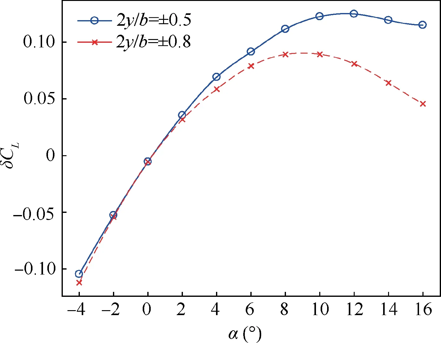
Fig. 11 CL difference between symmetric sections 2y/b=±0.5 and±0.8 (Wing AR=5, h/c=0.5, and φ=5°).
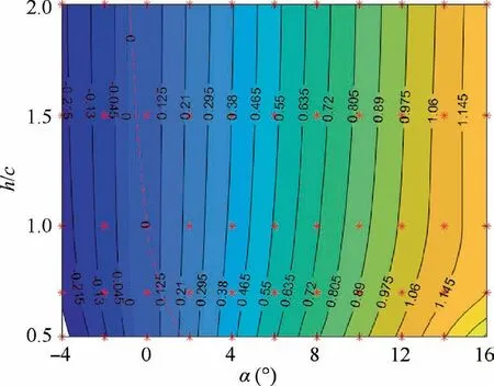
Fig. 12 CL increment counter and zero-rolling-moment curve(red dashed line) of wing with AR=6 and φ=5°.
3.1.3. Effect of AR on rolling moment.
The effect of the AR is multifaceted. Taking the AR increase as an example, there are two ways that the AR can cause the Cto change.
(1) For wings with equal chord lengths,the wing with a larger AR has a larger span, and the increase in span increases the height difference between the two sides when the wings are banked at the same angle. This change directly increases the rolling moment.

Fig. 13 CL vs AOA curve of left and right half of wing with AR=6, h/c=0.5, and φ=5°.
The difference in the rolling moment coefficient contour on the height vs AOA plane is shown in Fig. 15. Two zero-ΔCcurves lie on the plane. The first one, which is approximately lies from h/c=2, α= -0.9° to h/c=0.5, α=1.9°, is in the zone where the wing has a positive C.In this zone,a larger Cindicates a larger influence of the ground effect.The second curve, which approximately lies from h/c=2, α=3.8° to h/c=0.5, α=10.7°, is in the right part of the plane where Cis negative, and a smaller Cindicates a larger influence of the ground. The second curve divides the plane into halves:to the left of the curve,the wing of AR=7 is influenced more by the ground, and vice versa.

Fig. 14 A wing of AR=7 and φ=5° and a wing of AR=5 and φ=7°.
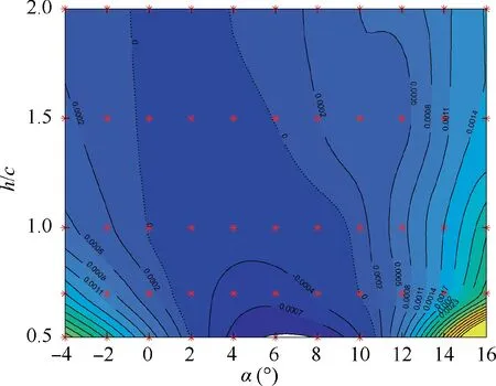
Fig. 15 ΔCl between wing of AR=7 and φ=5° and wing of AR=5 and φ=7°.
3.2. Yawing moment
3.2.1. Relationship between yawing moment and longitude
parameters
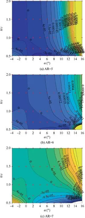
Fig. 16 Yawing coefficient contours of wings.
The yawing moment contours of three wings with AR=5, 6,and 7 are shown in Fig.16.The red stars in the contour represent the calculated states, while the others are obtained by interpolation or extrapolation. It can be seen the contour of the yawing moment is a saddle shape, indicating the complex behavior of the yawing moment coefficient C. Two zeroyawing-moment lines divide the AOA vs the height plane into 3 parts: a negative zone from the upper left to the lower right and two positive zones at the upper right and lower left corners. The positive yawing moment tends to move the lower half backward. The yawing moment due to the asymmetric ground effect is relatively small. For example, a wing with AR=6 at height h/c=2 and α=8°, which is a typical AOA during landing, the Cdue to bank is approximately 0.00012. A typical general aviation aircraft has a Cof approximately 0.0012 (per degree), which is an order of magnitude larger than the Cdue to banking.
The yawing moment in banked wings is caused by an uneven drag distribution. A typical drag distribution is shown in Fig. 17. The drag coefficient Cnear wingtip is relatively large because the induced drag is significant there. Take α=12°as example,the maximum drag of the left half is about 0.075 at 2y/b= -0.95 and the right half is about 0.069 at 2y/b=0.95.
The yawing moment is determined by the drag, which is influenced by the bank angle, height, and AOA. The drag of a wing in ground effect has both a contribution from the CDGE and SDGE. Studies have revealed that the CDGE increases drag and slightly increases the minimum-drag AOAand its effect strengthens as the height decreases. In this paper, the left half is lower and has more drag increase due to the CDGE, which results in a positive yaw moment.
The SDGE changes the lift distribution, so the induced drag changes. Studies have shown that the induced drag decreases as the height decreases,so the lower half will have smaller drag, and generates an ‘‘adverse yaw moment”. The influence of the SDGE significantly depends on the lift, and its influence diminishes when the AOA is near a zero-lift AOA. In this research, the left half is lower, so the induced drag should be smaller and result in a negative yaw moment.The final resulting yaw moment is that the effect of CDGE and SDGE oppose each other.
3.2.2. Effect of AR on yawing moment
To find the influence of the AR on the yaw moment, consider two wings with AR=7, φ=5° and AR=5, φ=7° again.As previously mentioned, the influence of the CDGE is eliminated by subtracting their yawing coefficient(AR=7,φ=5°subtracts AR=5, φ=7°). The resulting ΔCis shown in Fig.18.
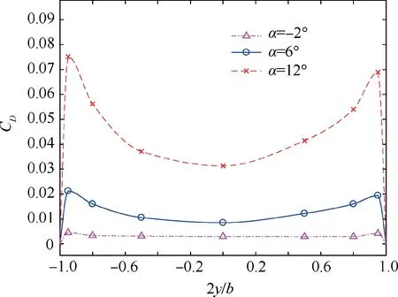
Fig. 17 Drag distribution of wing with AR=7, h/c=0.7, and φ=5°.
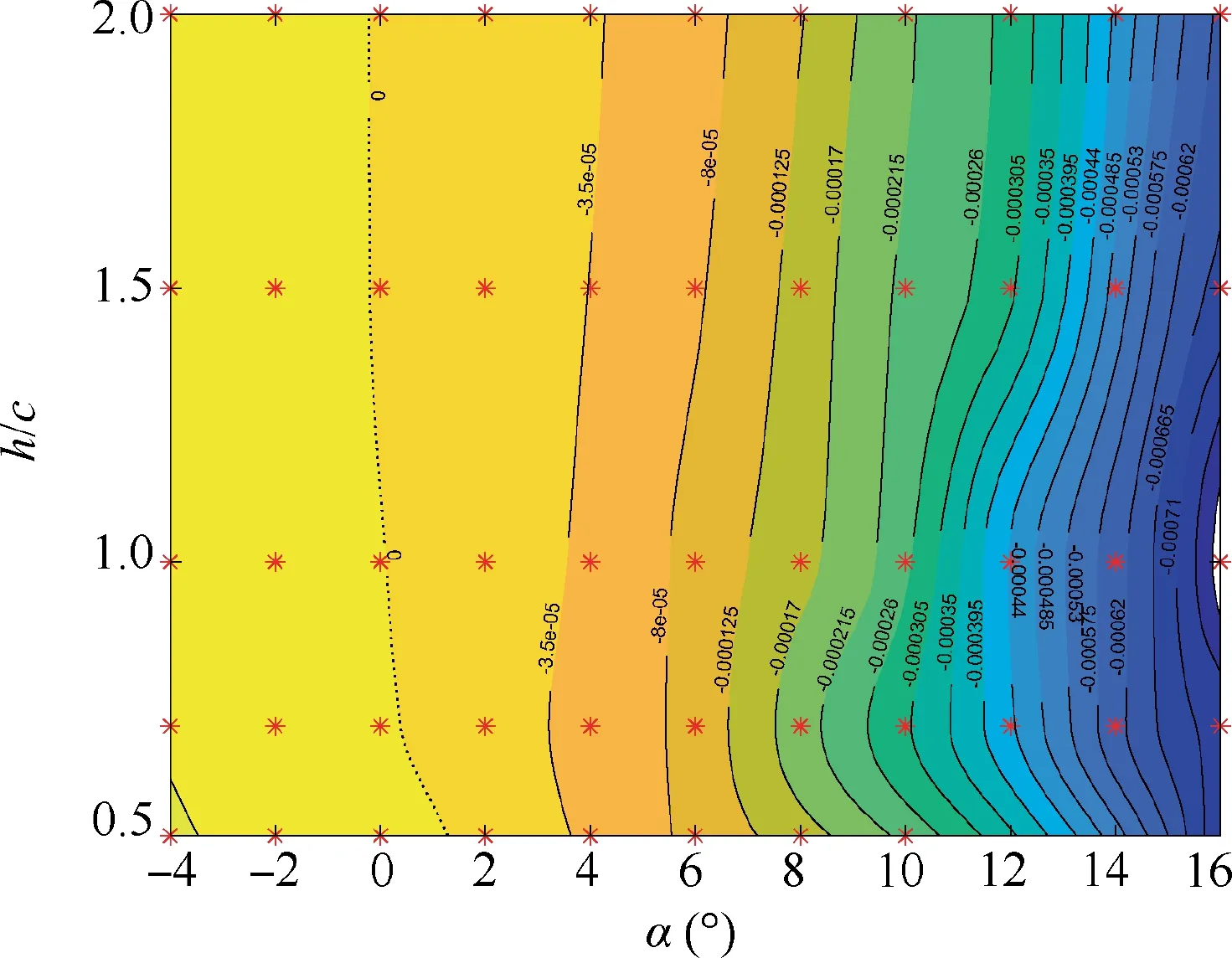
Fig. 18 ΔCn between wing of AR=7 and φ=5° and wing of AR=5 and φ=7°.
As Fig.18 shows,the ΔCand Cof the wings are about the same size.The height vs.the AOA plane is divided into a negative zone and a positive zone. As mentioned before, SDGE causes the lower half of a wing has smaller drag and causes the wing to generate negative yawing moments. In most of the positive AOA zones on the plane,ΔCis negative,indicating that the wing with AR=7 has a smaller C,i.e.,it is more influenced by SDGE. The contour is nearly vertical, which indicates that ΔCis almost independent of height.
The reason why yawing moment has a complex behavior can be briefly summarized as follow: the yawing moment depends on drag distribution of the wing,and SDGE generates an adverse moment while CDGE generates an oppose one.The influence of SDGE increase if the wing AR rises.
4. Conclusions
This work demonstrated that the roll and yaw moments are generated due to the ground effect on the banked wings, and both are affected not only by the bank angle but also by AOA, height, and AR.
The rolling moment has contributions both from CDGE and SDGE, and may be large enough to cause difficulties in control when height is small, but diminishes quickly as the height increases. At most positive AOAs, the rolling moment tends to decrease the bank angle, acting as a ‘‘righting moment”, but becomes less effective as the AOA decreases.When the AOA is less than a zero-roll-moment-AOA,the rolling moment reverses and tends to increase the bank angle,acting as a ‘‘divergent moment”. Besides, rolling moments have other two characteristics, there are:
(1) Zero-roll-moment-AOA is slightly larger than zero-lift AOA, and even larger when the height decreases, mainly due to CDGE.
(2) The rolling moment vs AOA derivative dC/dα first increases with AOA, and then decreases. It usually starts before the wings reach stall AOA because the decreases of dC/dα are mainly due to bend of lift-curve of the wing.
The yawing moment of the wing is mainly dominated by the drag distribution and exhibits complex behavior because CDGE and SDGE generate yawing moments oppose each other. CDGE governs the yawing moment in this paper.
AR can influence Cby changing the lift distribution on the wing.In this research when α<10°,the wings have larger AR experience a larger Cinfluence due to the ground effect. AR also has impact on C,but it is almost unrelated to the dimensionless height h/c.
Having these knowledges helps bridge the AOA and height influence lateral movements in ground effect. Control-law designers of WIG crafts could make more targeted modifications to the turning logic. Conceptual designers could modify the wing geometry to take advantage of these moments or keep away from them. Further work could be building analytical and smooth models for these moments, which could enable the model-based control system design and help reduce the workload of CFD.
The authors declare that they have no known competing financial interests or personal relationships that could have appeared to influence the work reported in this paper.
The work described in this paper was partially supported by the National Natural Science Foundation of China (No.51805019).
 Chinese Journal of Aeronautics2022年3期
- Chinese Journal of Aeronautics的其它文章
- Film cooling performance and flow structure of single-hole and double-holes with swirling jet
- Lock-in phenomenon of tip clearance flow and its influence on aerodynamic damping under specified vibration on an axial transonic compressor rotor
- Solid rocket propulsion technology for de-orbiting spacecraft
- Bioinspired polarized light compass in moonlit sky for heading determination based on probability density estimation
- Effects of sweep angles on turbulent separation behaviors induced by blunt fin
- Design and analysis of a novel hinged boom based on cable drive
