
Fabrication and Investigation on Double-Hollow Shell CoFe Oxide@TiO2 Nanocube with Superior Electromagnetic Properties
2022-03-12 13:29:32NIXinyaoTANGChuanhaoHUAJiasongCHENYiZHUANGQixin
上海航天 2022年1期
NI Xinyao,TANG Chuanhao,HUA Jiasong,CHEN Yi,ZHUANG Qixin
(1.School of Materials Science and Engineering,East China University of Science and Technology,Shanghai 200237,China;2.Shanghai Spaceflight Precision Machinery Institute,Shanghai 201600,China)
Abstract:Electromagnetic wave absorbing materials are urgently required in the fields of medicine,communication,and military.However,the thickness,weight,narrow effective bandwidth,and weak absorbing ability of the materials restrict their further application.In this work,a double-layer hollow nanocube with a dielectric titanium dioxide(TiO2)shell and a magnetic CoFe oxide inner shell is prepared.Prussian blue(PB)is prepared by the hydrothermal method,and used as the template to prepare PB@CoFe PB analogue(PBA).After selective etching and further calcination,hollow CoFe oxide particles are obtained.The obtained particles are then coated with SiO2 and TiO2,respectively,and the intermediate layer is dislodged to obtain the final CoFe oxide@TiO2 with the hollow double shell structure.The obtained double-layer hollow structure can effectively capture the incident electromagnetic waves,and increase the propagation path.Moreover,the obvious enhancement of interface polarization and the improvement of impedance matching enhance the wave absorbing ability of the material.The analysis results show that,the structure is stable and the dispersion is good.The maximum reflection loss(RL)at 10 GHz is as high as-46.1 dB with the sample thickness of 1.6 mm.The light-weight and high-efficiency CoFe oxide@TiO2 absorber is promised to be used in commercial and military aerospace fields.
Key words:microwave absorption;CoFe oxide;titanium dioxide(TiO2);dual-shelled dual-cavity structure;nanocube
0 Introduction
The electromagnetic radiation pollution brought by the progress of electromagnetic wave technology and the evergrowing demand for stealth materials in the military call for broadband,efficient,and light‑weight electromagnetic wave absorbing materials.Recently,tremendous efforts have been devoted to constructing high-efficiency absorbing materials,e.g.,physically mixing magnetic materials with dielectric materials and depositing magnetic materials on a two-dimensional conductive network.Howev‑er,there are still many unresolved problems for tradi‑tional absorbing materials.For example,the nano‑system prepared by the sol-gel method is prone to spontaneous agglomeration,and thus ordinary physi‑cal mixing can hardly distribute the dielectric and mag‑netic components uniformly.Therefore,the prep‑aration of uniform and dispersed high-performance absorbing materials still faces many challenges.
In order to solve the above problems,research‑ers turn to design the microscopic morphology of ab‑sorbing materials and control the size of nanoparticles,e.g.,one-dimensional structures like nanotubes and nanorods,two-dimensional structures like nano‑films and nanosheets,and three-dimensional struc‑tures like sea urchin structures and core-shell struc‑tures.Among three-dimensional absorbing materi‑als,the core-shell structured absorbing materials with strong ferromagnetic resonance properties and domain wall displacement,e.g.,FeO,become popular can‑didates,which would nevertheless lead to greater den‑sity and unavoidable narrow absorption band‑widths.LIU et al.prepared a series of CoNi,i.e.,CoNi@SiOcore-shell,CoNi@SiO@TiOcoreshell,and CoNi@Air@TiOegg yolk shell micro‑spheres,and concluded that the reflection loss(RL)value of the CoNi@SiO@TiOabsorber was the greatest.It is proved that the rich interface polarization of the multi-layer hierarchical shell structure contrib‑utes to scattering microwaves repeatedly,which in turn leads to the absorption and depletion of the micro‑waves.Researchers have also found that the micro‑scopic shape of nanoparticles has a huge impact on the absorbing performance of the nanoparticles.The performance of nanoabsorbing materials with irregu‑lar shapes,e.g.,cubes and flowers,are better than that with a regular spherical shape in most cases.For example,LIANG et al.prepared a metal-or‑ganic framework cube from Prussian blue analogue(PBA)after heating treatment.They obtained that the CoFe/C nanoabsorbent material had a minimum reflection loss value of -44.6 dB with the material thickness of 2.15 mm,and the effective bandwidth could reach 5.5 GHz.The precise cube structure may bring exchange resonance at high frequencies,and most of the polyhedral materials are anisotropic,con‑tributing to the higher coercivity and hysteresis loss.
Inspired by this,we take the advantages of CoFe oxide and titanium dioxide(TiO)to construct a novel double-hollow shell cubic structure.The air layer is expected to ensure that most of the incident microwave penetrates the small impedance gap mag‑netic core.The CoFe oxide covers the inner template Prussian blue(PB),which is selectively etched after cladding.Then,silicon dioxide(SiO)and TiOare,respectively,coated on the surface of the pre‑pared hollow CoFe oxide core,and the middle SiOlayer is selectively etched to obtain the double-layer hollow CoFe oxide@TiO.CoFe oxide is a hard mag‑netic material with high saturation magnetization and coercivity,which are tens of times of those of ordi‑nary magnetic alloys,and has excellent magnetic loss performance and strong chemical stability.TiOhas high dielectric constant and good dielectric loss performance.The combination of CoFe oxide and TiOcan effectively improve the absorbing effi‑ciency.On the one hand,through the impedance matching with the air medium,not only the wave ab‑sorbing can be ensured but also the loss of micro‑waves inside the material can be increased and the density of the final material can be reduced.On the other hand,the cubic microscopic shape can in‑crease not only the transmission of the incident waves inside the material but also the contact area between the incident wave and the two layers of the absorb‑ing materials.The minimum reflection loss of the fi‑nal double-layer hollow CoFe oxide@TiOreaches-46.1 dB at 10.0 GHz with stable structure and good dispersion(6.32 GHz effective bandwidth).In summary,it is a new type of“thin,wide,light,and strong”absorbing material,and is expected to be used in commercial and aerospace fields.
1 Materials and methods
1.1 Chemicals and materials
Potassium ferricyanide,cobalt chloride hexahy‑drate,sodium citrate,polypropylene pyrrolidone(PVP),tetraethyl orthosilicate(TEOS),tetrabutyl titanate(TBOT),ethanol,acetone,concentrated hydrochloric acid,and concentrated ammonia solu‑tions(28%)are of analytical grade.They are pur‑chased from Shanghai Chemical Company,and used as received.
1.2 Synthesis of PB
Polyvinylpyrrolidone(PVP)(1 g),sodium ci‑trate(0.3 g),and potassium ferricyanide(K[Fe(CN)])(0.11 g)are mixed in the 30 mL ethanol aqueous solution where the volume ratio of ethanol to water is 1∶2.Then,0.4 mL concentrated hydro‑chloric acid is added to the above solution and stirred for 10 min.The mixture is removed into a hydrother‑mal kettle and reacts at 80 °C for 12 h.After the re‑action,the blue product(PB)is centrifuged and washed three times with deionized water and etha‑nol,and then dried in vacuum oven.
1.3 Synthesis of PB@CoFe PBA
20 mg PB is firstly dispersed and sonicated in 30 mL deionized water,and then 143 mg cobalt chloride hexahydrate,0.3 g PVP,and 0.25 g sodi‑um citrate are added.The obtained liquid is recorded as Solution A.Then,66 mg potassium ferricyanide is added to 20 mL deionized water,and the solution is marked as Solution B.Solution B is added to Solu‑tion A with a dropper at a slow rapid and stirred for 10 min.The mixture ages for 24 h at room tempera‑ture,and after that the final PB@CoFe PBA is ob‑tained through centrifugation and three times wash with deionized water and ethanol.
1.4 Synthesis of hollow CoFe oxide
Take 0.075 g product obtained in the previous step,and disperse it into 15 mL ethanol by sonica‑tion.Then,add 15 mL 0.04 mol/L NaOH solution to the dispersion,and stir for several minutes to etch PB.The resulting product is obtained by centrifuga‑tion and washed three times with water.After that,the washed product is ultrasonically dispersed in 30 mL eionized water,and 0.25 mL concentrated HCL is added.After centrifugation and three times water wash,the hollow CoFe PBA is obtained.To prepare the final hollow CoFe oxide,the hollow CoFe PBA should be removed to a calciner and be calcinated at 300 °C for 2 h(air atmosphere)at the heating rate of 0.5 °C/min to avoid structural collapse.
1.5 Synthesis of hollow CoFe oxide@SiO2
Take 0.016 g product from the above step,and ultrasonically disperse it in 30 mL deionized water.Then,add 0.5 g PVP to the dispersion,and stir for 12 h.After reaction,the reaction solution is centri‑fuged and washed three times with water.Ultrasoni‑cally disperse the product in 71 mL ethanol aqueous ammonia solution(the volume ratio of ethanol,de‑ionized water,and ammonia water is 56∶14∶1),and add 0.06 mL tetraethyl silicate in the solution at a uniform speed.After 12 h stir and reaction,the hollow CoFe oxide@SiOis obtained.Wash the ob‑tained product three times with deionized water and ethanol,and dry it for later use.
1.6 Synthesis of hollow CoFe Oxide@SiO2@TiO2
Prepare 90.3 mL mixed solution of ethanol,ac‑etone,and ammonia(the volume ratio of ethanol,acetone,and ammonia is 40∶50∶0.30),add the product obtained in the previous step to the prepared mixed solution,and disperse by ultrasound.Take 0.24 mL tetrabutyl titanate,dissolve it in 10 mL eth‑anol,then add the obtained mixture to the above mixed solution.Stir and react at room temperature for 2 h.The product is separated by centrifugation,washed with deionized water and ethanol for three times,and dried.Finally,the dried product is cal‑cined at 500 °C for 2 h(air atmosphere)under the heating rate of 1 °C/min to obtain hollow CoFe ox‑ide@SiO@TiO.
1.7 Synthesis of double-layer hollow CoFe oxide@TiO2
The product of the above steps is ultrasonic dis‑persed to 40 mL deionized water with the addition of 0.2 g NaOH and stirred for 6 h at 60 °C to etch the SiO.The obtained new product is centrifugat‑ed,separated,and washed three times with deion‑ized water and ethanol.After dry,the final product,i.e.,double-layer hollow CoFe oxide@TiO,is ob‑tained.The preparation procedure is shown in Fig.1.

Fig.1 Schematic diagram of the preparation of double-layer hollow CoFe oxide@TiO2
2 Characterization
The morphology and crystalline structure of the as-prepared samples are characterized by field-emis‑sion scanning electron microscopy(FESEM,Hitachi S-4800)and transmission electron microscopy(TEM,JEOL-2100F).An X-ray diffraction(XRD)analysis is carried out on a D/MAX 2550 VB/PC ro‑tating anode X-ray multicrystal diffraction spectrome‑ter equipped with Ni-filtered Cu Kradiation.The magnetic properties are determined with a supercon‑ducting quantum interference device(SQUID).The electromagnetic properties(i.e.,relative complex permittivity and permeability)are measured on a vec‑tor network analyzer(VNA),Agilent E8363B,with the coaxial transmission line method over the frequen‑cy range from 2 GHz to 18 GHz.The samples are pre‑pared by mixing 60% of hollow CoFe oxide,hollow CoFe oxide@SiO@TiO,and double-layer hollow CoFe oxide@TiO,respectively,with 40% paraffin wax,as the paraffin wax barely contributes to permit‑tivity and permeability.The obtained samples are then molded into toroids with an outer diameter of 7 mm,an inner diameter of 3 mm,and a thickness of 3 mm.Thermogravimetric analysis(TGA)is con‑ducted at the heating rate of 10 °C·minunder the ni‑trogen gas flow.
3 Morphology and structural characteri‑zation
The PB is prepared by the polymer-assisted hydrothermal method,which can effectively avoid excessive crystallization speed due to high tempera‑ture to obtain uniform cubic form,as shown in Fig.2(a).Hollow CoFe oxide is obtained after etching the PB core and calcining.The surface of the CoFe oxide nanocube is coated with SiOthrough the hydrolysis of tetraethyl silicate under the pH condition of the ammonia water.Moreover,the external layer is covered by TiO,and SiOis selectively etched to form another hollow layer.From Fig.2(a),it can be seen that the synthesized PB nanocubes are offspherical and have a uniform particle size distribution with a side length of about 220 nm.
The outer layers are not obvious after coated with CoFe under TEM,while the side length in‑creases to 240 nm and the edge becomes sharper,as shown in Fig.2(b).The PB inside the nanoparticle is further etched by the NaOH solution to form a spherical cavity,leaving a shell with a thickness of 20 nm,as shown in Fig.2(c).It can be clearly ob‑served in Fig.2(d)that the CoFe oxide formed after calcination is still cubic,but the outer layer structure is more loose.After the subsequent coating of SiO,the nanoparticle is still cubic and there is a clear gap between the uniform 20 nm thick SiOlayer and the CoFe oxide(see Fig.2(e)).
From Fig.2(f),it can be seen that the nanoparticle is a cube with soft corners after further coating with 40 nm thick TiO.After the second etching,the double-layer hollow nanocube is finally obtained.The Fe,Ti element mapping is shown in Fig.2(g).The thickness of the cavity is about 20 nm,and the interface between the layers is smooth,which proves that SiOhas been completely etched and the obtained double-layer hollow CoFe ox‑ide@TiOhas good structural stability,which is fur‑ther confirmed in the XRD.

Fig.2 SEM,TEM,and mapping images of microspheres obtained from the synthesis of CoFe oxide@TiO2
The XRD patterns of hollow CoFe oxide,hollow CoFe oxide@SiO,hollow CoFe oxide@SiO@TiOand double-layer hollow CoFe oxide@TiO,are shown in Fig.3.It can be seen that with the diffrac‑tion peaks of the hollow CoFe oxide structure at 2=35.4°,57° and 62.6° correspond to the peak data of PDF#22-1086,indicating that the sample formed is CoFeOwith the inverse spinel face center cubic(FCC)structure.Owing to the existence of the broad carbon peak around 25° and the amorphous structure of silica,the peak shape of hollow CoFe oxide@SiOdoes not change significantly after coat‑ing SiO.Furthermore,the obvious characteristic peaks appear at 25.3° and 48° prove the success of TiOcoating and the subsequent etching does not af‑fect the structure of TiO.
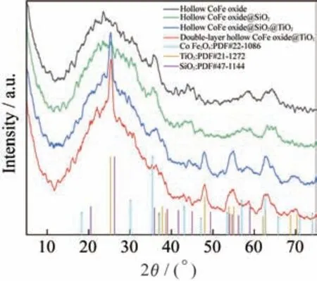
Fig.3 XRD of hollow CoFe oxide,hollow CoFe oxide@SiO2,hollow CoFe oxide@SiO2@TiO2 and double-layer hollow CoFe de@TiO2
4 Magnetic and microwave absorbing properties
In order to explain the microwave absorbing mechanism by double-layer hollow CoFe ox‑ide@TiO,the microwave absorption model is depict‑ed in Fig.4.On the one hand,CoFe oxide@TiOcon‑sisting of dielectric shell TiOand magnetic core CoFe oxide contributes to the excellent absorbing per‑formance.Due to the effective void space between the magnetic and dielectric components,impedance matching can be promoted according to the complex permittivity and permeability.According to the Max‑well-Wagner effect,the inevitably discontinuous ar‑eas or defects in the interfaces brought by the doublelayer structure inside the particles will lead to corre‑sponding charge accumulation,which will bring inter‑face polarization.On the other hand,the microwaves incident on the CoFe oxide@TiOmicrospheres can pass through the outer TiOshell,and may be further reflected on the CoFe oxide core,causing multiple re‑flections of electromagnetic waves between the core and the shell.The dielectric TiOshell and the magnet‑ic CoFe oxide core will produce adjustable reflection loss.The incident wave energy can quickly convert in‑to heat and dissipated because of the block of the two layers of cavity.On the whole,the density is greatly re‑duced due to the presence of air in the cavity,which is very important for the design of lightweight absorbers.

Fig.4 Microwave absorbing mechanism experienced by double-layer hollow CoFe oxide@TiO2
Theoretically,the magnetic field radiated by the CoFe oxide core can penetrate the oxide shell,and magnetically couple and interact with adjacent micro‑spheres to form a magnetic absorption network.As shown in Fig.5,the magnetic field properties of hol‑low CoFe oxide,hollow CoFe oxide@SiO@TiO,and double-layer hollow CoFe oxide@TiOfrom-2 387 kA/m to 2 387 kA/m are studied on the SQUID magnetometer(temperature:300 K).None of the three hysteresis loops shows remanence or co‑ercivity,indicating that all the three samples exhibit quasi-superparamagnetism at room temperature.The saturation magnetization()of hollow CoFe oxide is about 10.8 emu·g.
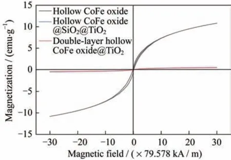
Fig.5 Hysteresis loops of hollow CoFe oxide,hollow CoFe oxide@SiO2@TiO2,and double-layer hollow CoFe oxide@TiO2
After the hollow CoFe oxide is coated with SiOand TiOin sequence,thevalues of FeO@SiOcore-shell microspheres and FeO@SiO@TiOdou‑ble-layer core-shell microspheres are reduced to around 0.5 emu·g.This is because the cladding lay‑ers SiOand TiOare non-magnetic.In order to reveal the microwave absorbing properties of the asprepared samples,we measure the complex permit‑tivity(,)and complex permeability(,)of the three-step product in the frequency range from 2 GHz to 18 GHz to study the microwave absorption performance of the final product(see Fig.6).Owing to the dielectric property promotion brought by the outermost TiO,andof double-layer hollow CoFe oxide@TiOare relatively high and stable com‑pared with those of hollow CoFe oxide and hollow CoFe oxide@SiO@TiO.This may also be ascribed to the introduction of the cavity which increases the polarization area and generates more polarization charges.This further explains the reason whyin‑creases slightly as the frequency increases.The final product,i.e.,double-layer hollow CoFe ox‑ide@TiOmicrospheres,has a larger dielectric loss tangent value than other samples,and the magnetic loss tangent value is relatively high,between 0.20 and 0.28.It is anticipated that electromagnetic waves will experience a large degree of attenuatio,resulting in strong microwave absorption.
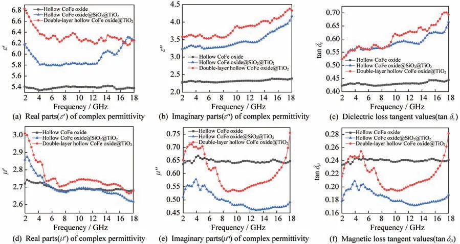
Fig.6 Complex permittivity,complex permeability,and loss tangent values of hollow CoFe oxide,hollow CoFe oxide@SiO2@TiO2,and double-layer hollow CoFe oxide@TiO2
The reflection loss()is another crucial pa‑rameter to assess the microwave absorption perfor‑mance.can be deduced from the transmission line theory based on the measured relative permittivity and permeability as follows:
whereis the microwave frequency,is the thick‑ness of the absorber,is the speed of light,andandare the complex relative permittivity and the com‑plex relative permeability,respectively.The micro‑wave absorption capacity is stronger when the value ofis lower.The reflection loss values of hollow CoFe oxide,hollow CoFe oxide@SiO@TiO,and double-layer hollow CoFe oxide@TiOare obtained from the above formulae.
As shown in Figs.7(a),7(b)and 7(c),thepeaks of all three samples shift from low frequency to high frequency with the decrease in the thickness.
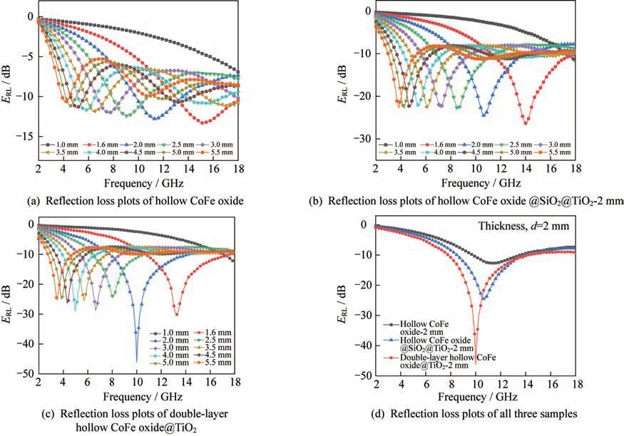
Fig.7 Reflection loss plots of hollow CoFe oxide,hollow CoFe oxide@SiO2@TiO2,and double-layer hollow CoFe oxide@TiO2
It is worth noting from Fig.8(d)that the mini‑mumof the hollow CoFe oxide is -12.8 dB and decreases to -24.6 dB after coating with SiOand TiO,while the minimumof double-layer hollow CoFe oxide@TiOis -46.1 dB with a thickness of 2 mm.This indicates that the existence of TiOnot only balances the original impedance but also increas‑es the dielectric loss.More importantly,after the selective removal of SiO,the resulting CoFe ox‑ide@TiOexhibits the best microwave absorbing performance among hollow CoFe oxide,hollow CoFe oxide@SiO@TiO,and double-layer hollow CoFe oxide@TiO.In addition,the absorption band‑width withlower than -10 dB(the reflection loss is more than 90%)reaches up to 6.32 GHz,which is also an increase over 5.44 GHz CoFe ox‑ide@SiO@TiOand 3.76 GHz CoFe oxide.It also reveals the superiority of the double cavity structure.It is supposed that the incorporation of dielectric TiOas well as the magnetic CoFe alloy into the mi‑crowave absorption system has generated massive magnetic and dielectric dipole interactions at the ma‑terial interfaces,and has a positive effect on the matching of permittivity and permeability.
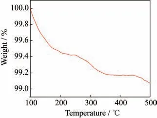
Fig.8 TGA curve of double-layer hollow CoFe oxide@TiO2
In order to preliminarily estimate the use condi‑tions of the material,we conduct a TGA test on the fi‑nal product.The results show that the mass loss does not exceed 1% at a high temperature of 500 °C(see Fig.8),indicating that the material has good thermal stability with the potential for high temperature and other harsh environments.
5 Conclusions
In summary,hollow CoFe oxide,hollow CoFe oxide@SiO@TiO,and double-layer hollow CoFe oxide@TiOare successfully synthesized.The archi‑tecture and compositions of properly designed dual shells and dual cavities(i.e.,magnetic CoFe oxide and dielectric TiOfor achieving optimal magnetic and dielectric loss)collectively render efficient trapping of the incident wave via multiple internal re‑flections and sufficient interfacial polarization,and markedly improve the impedance matching,which in turn contribute to the outstanding microwave absorp‑tion performance of double-layer hollow CoFe ox‑ide@TiO.The double-layer hollow CoFe ox‑ide@TiOabsorbers significantly enhance the micro‑wave absorption ability with the minimumup to-46.1 dB at 10 GHz with a thin thickness of only 2 mm and the absorption bandwidth up to 6.32 GHz(<10 dB).All these results have highlighted the su‑periority of dual shells and dual cavities,which may shed some light on the crafting of high-performance yet thin and lightweight microwave absorbers promis‑ing for use in electromagnetic radiation protection,in‑cluding mobile communication devices and amplitude modulation(AM)radio.

- 上海航天的其它文章
- 序言
- 企业简介
- Microstructure and Property Analysis of AerMet100 Steel Manufactured by In-situ Rolling Mixed Wire Arc Additive Manufacturing
- Linear Shaped Charge Cutting Property and Charge Cutting Mechanism of Mg-Gd-Y-Zn Alloy
- Effect of Isothermal Forging on the Microstructure and Mechanical Properties of Mg-8Gd-3Y-0.5Zr Alloy
- Investigation on Thermal and Dimensional Stability of Epoxy Resin In-Situ Modified by Cyanate Ester Resin and Polydimethylsiloxane