
Design and Kinematics Analysis of Support Structure for Multi-Configuration Rigid-Flexible Coupled Modular Deployable Antenna
2022-01-18 00:40:10TIANDakeFANXiaodongJINLuGUOZhenweiGAOHaimingCHENHanting
Aerospace China 2021年3期
TIAN Dake,FAN Xiaodong,JIN Lu,GUO Zhenwei,GAO Haiming,CHEN Hanting
1 School of Mechanical Engineering,Shenyang Jianzhu University,Shenyang 110168
2 School of Civil Engineering,Shenyang Jianzhu University,Shenyang 110168
Abstract:In order to meet the urgent need for diversified and multi-functional deployable antennas in many major national aerospace projects,such as interstellar exploration,the fourth phase of lunar exploration project,and the industrial application of BeiDou,a deployable antenna structure composed of hexagonal prism and pentagonal prism modules is proposed.Firstly,the arrangement and combination rules of pentagonal prism and hexagonal prism modules on the plane were analyzed.Secondly,the spatial geometric model of the deployable antenna composed of pentagonal prism and hexagonal prism modules was established.The influence of module size on the antenna shape was then analyzed,and the kinematic model of the deployable antenna established by coordinate transformation.Finally,the above model was verified using MATLAB software.The simulation results showed that the proposed modular deployable antenna structure can realize accurate connection between modules,complete the expected deployment and folding functional requirements.It is hoped that this research can provide reference for the basic research and engineering application of deployable antennas in China.
Key words:space deployable antenna,support structure,rigid flexible coupling,kinematics analysis,numerical simulation
1 INTRODUCTION
Deployable antenna is an indispensable key equipment in deep space exploration,satellite navigation,military reconnaissance and other fields,plus it is also at the frontier and a hotspot in international aerospace research.With the continuous development of aerospace technology,the demand for deployable antennas with large aperture,compact storage ability,light weight and high precision characteristics will continue to increase.Therefore,it is of great scientific research value and provides diverse application prospects to conduct such relevant research.
The modular deployable antenna can realize the rapid scaling of antenna aperture by changing its shape,size,number,combination and arrangement of modules.It has good versatility,high flexibility and strong expansibility.It is one of the ideal antenna configurations to meet the communication requirements of satellite multi-function,multi-band and large capacity.At present,the main deployable antennas that have been successfully applied in orbit are:the tetrahedral element deployable antenna on Mir space station,the hexagonal prism modular deployable antenna on ETS-VIII,and the tetrahedral element deployable antenna on HJ-1Cand BeiDou 3 GEO satellites.In the theoretical research field,Meguroand Mitsugihave introduced the design and test of the deployable antenna of ETS-VIII,but some key parameters and design details were not been published.Ozawa,et al.based on the ETS-VIII deployable antenna,changed each rib of hexagonal prism module into a three-fold form,so as to increase the antenna aperture and reduce the weight of the antenna.YUE et al.proposed a deployable antenna structure with hexagonal prism elements driven by telescopic rods,manufactured a prototype and conducted modal experiments.TIAN,et al.proposed the method of fitting a paraboloid with spherical surface,and proposed the torsion bar method and space projection method of constructing a spherical surface with hexagonal prism modules,and LIU,et al.proposed the space equal envelope circle method of constructing spherical surface with hexagonal prism modules,which laid a good foundation for modularization of the hexagonal prism deployable antenna.LIU,et al.proposed a 3R-3URU deployable mechanism to solve the problem that the deployable antenna of tetrahedral element could not be fully folded.GUO,et al.proposed to construct a modular mechanism with three tetrahedral elements,and then use multiplemodular mechanisms for modular networking.Compared with the non-modular structure,the storage ability of the modular tetrahedral deployable antenna structure has been improved,and the number of rods was reduced.
A variety of modular deployable mechanisms have been proposed in the above literature,and some of them have been successfully applied in orbit.However,at present,the typical structures all adopt a single configuration module,which is difficult to meet the needs of diversified and rapid development of China’s space missions.In this paper,a modular deployable mechanism composed of hexagonal prism and pentagonal prism modules with simple structure and compact storage ability is proposed,and its application in large deployable antennas is further explored.In addition,the modular modeling method proposed in this paper also has a certain reference value for tetrahedral,hexagonal prism modules and other deployable antennas to realize modular networking.
2 STRUCTURE AND COMPOSITION OF DEPLOYABLE ANTENNA
The modular deployable antenna is composed of a cable net structure and a support structure.The cable net structure is composed of a front cable net,a metal reflecting net,an adjusting cable and a back cable net.Its main function is to receive and transmit signals.The composition of the support structure is shown in Figure 1.A planar rigid deployable multi-link mechanism is used to form a pentagonal prism and a hexagonal prism support mechanism respectively.The pentagonal prism and hexagonal prism support mechanisms are rigidly transformed into a pentagonal prism and a hexagonal prism support structure respectively by flexible tension cables.The modular deployable antenna support structure is composed of several pentagonal prism and hexagonal prism support structures.The main function of the support structure is to pull the cable net structure to deploy,support and position the cable net structure,and provide sufficient stiffness and accuracy.

Figure 1 Composition of deployable antenna support structure
3 SPACE GEOMETRY MODELING
Referring to the method of a football skin forming a ball shape,the arrangement and combination of modules are studied,which are mainly divided into two kinds:a hierarchical arrangement and a circular array arrangement.When pentagonal prism and hexagonal prism shapes are combined,module 1 is recorded as the first layer and modules 2-6 as the second layer.Modules 3-6 can be seen as formed by module 2 through a 72° annular array around module 1,as shown in Figure 2.

Figure 2 Arrangement and combination of modules
As shown in Figure 2,one regular pentagonal prism and five hexagonal prisms can be seamlessly spliced on a plane.On a sphere,whether the combination of pentagonal prism and hexagonal prism continues to meet the law of the plane needs to be verified by spatial geometric modeling.The process of spatial geometric modeling is shown in Figure 3.Each pentagonal prism or hexagonal prism module is represented by an envelope circle with radiusr
,and then multiple envelope circles with radiusR
are“laid”on the same sphere with radiusr
according to the rule that any three adjacent circles have only one intersection point.The intersection coordinates of the envelope circle on the spherical surface are the coordinates of the connection points between the corresponding modules.According to these coordinates,multiple modules can be connected accurately.Through spatial geometric modeling,the plane figure shown in Figure 2 can be transformed from a plane to a surface.The main purpose of space geometry modeling is to find out the equations of several circles,and then to find out the coordinates of corresponding intersections.Taking theo
-point of the fitting ball as the coordinate origin,thez
-axis coincides with the axis of module 1,and the direction ofx
-axis is horizontal to the right.We establish the coordinate system as shown in Figure 4 according to the right-hand rule.Note that the center of the envelope circle of modulen
isS
and the radius of the envelope circle isr
.In Figure 4,O
,F
andG
are on the same line.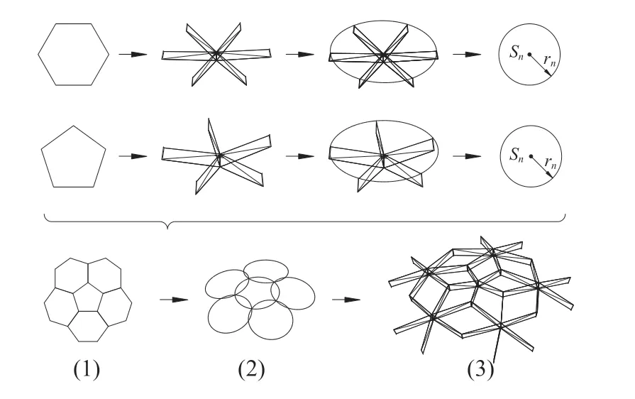
Figure 3 Process of spatial geometry modeling
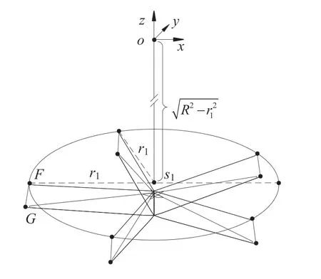
Figure 4 Coordinate system
According to the position relationship between modules,the envelope circle of all modules can be represented in the coordinate system shown in Figure 4,and Figure 5 is a top view diagram of the coordinate system (just a brief description of the position relationship,not a strict top view).
According to the geometric relationship in Figures 4 and 5,the coordinates ofs
point of the center of envelope circle 1 can be expressed as follows:
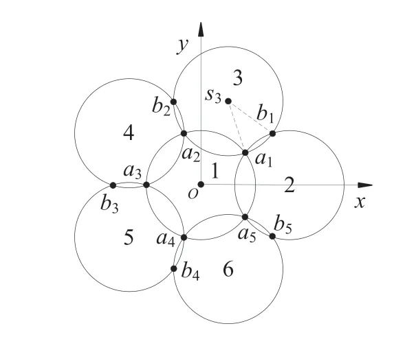
Figure 5 xoy view
Module 1 is a regular pentagon,and pointsa
anda
are symmetric with respect to thexoz
plane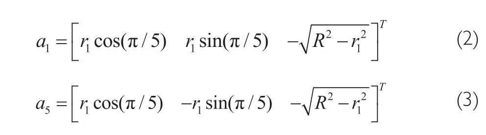
a
anda
,the coordinates ofS
,the center of enveloping circle 2,can be obtained by Equation (4),
S
can be obtained by solving Equation (4)
S
-S
of the envelope circles 3-6 can be expressed as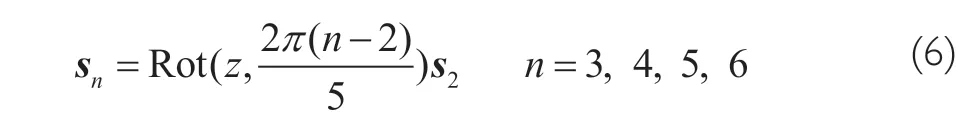
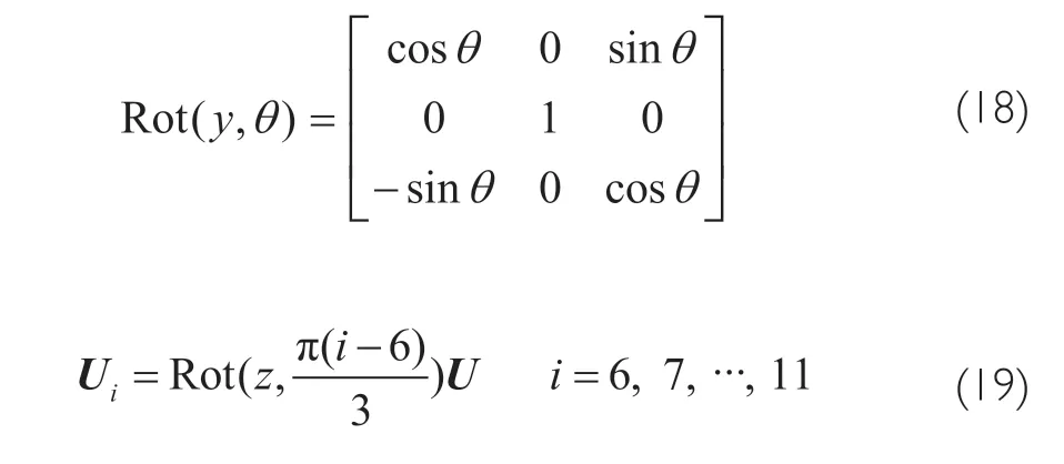
Rot
(z,θ
) is the coordinate transformation formula of rotation aroundz
axis,
In the space rectangular coordinate system,the equation of a circle is usually the intersection of plane and sphere.Therefore,the equations of the above six enveloping circles can be expressed as
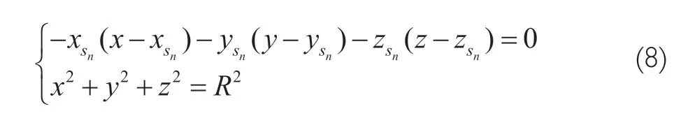
s
is shown in Equations (1),(5) and (6).Pointb
is the intersection point of enveloping circles 2 and 3,which can be obtained by the equations of enveloping circles 2 and 3.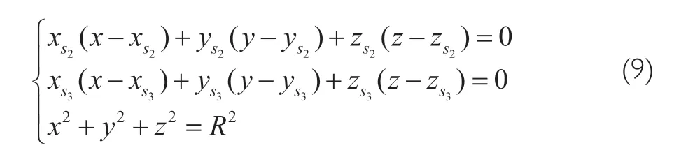
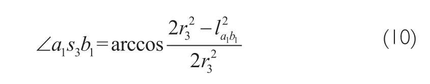
a
andb
respectively.
r
=r
=r
=r
=r
.The spatial geometric modeling can calculate the coordinates of the module connection points,and connect the corresponding module to the corresponding position according to the coordinates,so as to realize the accurate connection of the module.
4 KINEMATIC MODEL
The rib unit mechanism is shown in Figure 6,and the position shown in the figure is a certain position during the expansion process of the rib unit.The pentagonal prism module is composed of five rib units,and the hexagonal prism module is composed of six rib units.The kinematic analysis of the modular deployable antenna support mechanism needs to start from the rib unit,and then complete the coordinate transformation from the rib unit to the module and to the whole deployable antenna support mechanism according to the coordinate transformation theory.

Figure 6 Rib unit
The coordinate system in Figure 6 is the same as that in Figure 4.When the rib unit is fully deployed,pointsC
andF
are on the spherical surface with radiusr
,and pointsO
,F
andG
are collinear.According to the geometric relationship in Figure 6,the following closed-loop equation can be obtained
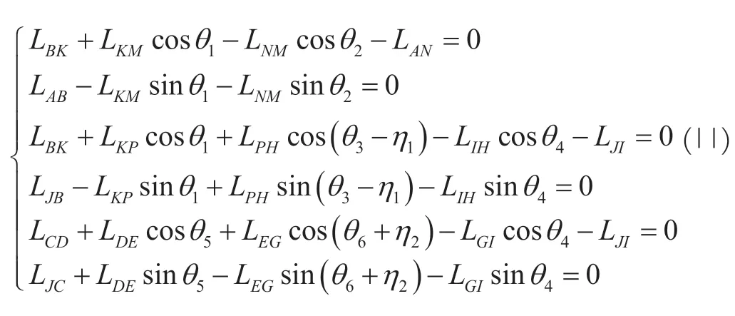
η
=arctan(L
/L
),η
=actan(L
/L
).The deflection angleθ
:θ
corresponding to the displacement of the sliderL
can be obtained from Equation (11).Therefore,when the slider displacement isL
,the coordinate ofH
point can be expressed as a column vector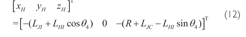
U
as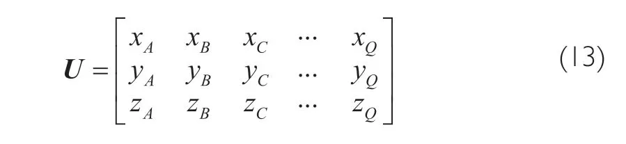
U
is the kinematic equation for the rib unit.Module 1 is composed of five rib units,so the kinematic equationM
of module 1 can be expressed as
M
of module 2 can be expressed as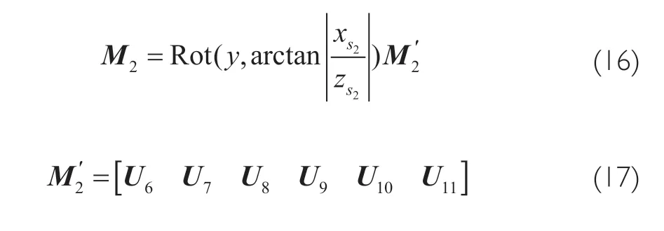
The kinematic equations of modules 3-6 can be expressed as
Therefore,given the slider displacement,the coordinates of any point on the deployable antenna support mechanism in the coordinate system can be obtained from the above model.
5 MODEL VALIDATION AND ANALYSIS
In order to verify the envelope circle model,the spatial geometric model and the kinematic model of the deployable antenna support mechanism,the numerical simulation software MATLAB was used to verify the above models and analyze the results.
5.1 Verification of the Spatial Geometric Model Two cases were verified and analyzed.
5.1.1 The radii of seven envelope circles are equal
TakeR
=4701 mm,r
=r
=r
=r
=r
=r
=600 mm,using MATLAB to verify the envelope circle model represented by equation (8),and the simulation results are shown in Figure 7.The six envelope circles can be accurately connected as expected.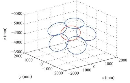
Figure 7 Envelope circle model
Taking the length of the central rod (JC
in Figure 6) as 150 mm,according to the connection point coordinates calculated by the envelope circle model,the connection of six modules can be simulated by MATLAB software.The simulation results are shown in Figure 8.The six modules can be accurately connected together as expected,but the angle deflection between the second layer modules is large.Note that the distance betweena
b
in Figure 5 isl
,setR
=4701 mm,r
=600 mm,r
as variables,and we can find the appropriater
value under the condition of ensuring the accurate connection of modules.The meaning ofL
value is shown in Equation (21).The relationship betweenr
andL
calculated by the model is shown in Figure 9.It can be seen from Figure 9 that whenr
=4701 mm,r
=600 mm andr
value is around 830,the structure is relatively harmonious.

Figure 9 Relationship between r2 and L
5.1.2 The radii of enveloping circles 2-6 are equal
WhenR
=4701,r
=600,r
=r
=r
=r
=r
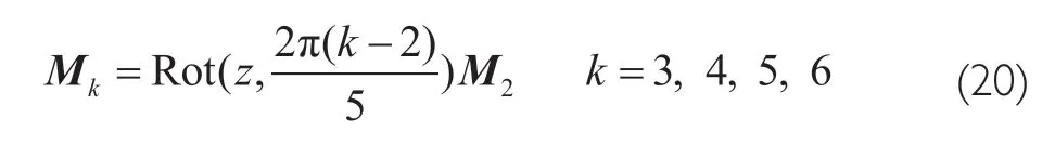
=830,the simulation results of envelope circle model and spatial geometry model of deployable antenna in MATLAB are shown in Figure 10 and Figure 11.Comparing with Figure 8 and Figure 11,it can be found that whenr
=600 mm andr
=830 mm,the structure is more harmonious.5.2 Kinematic Model Verification
Each module is driven by a spring slider to realize the deployment of the module.When we set the stroke of the slider to 55 mm,and move at a uniform speed of 1 mm/ s,then the simulation of the whole deployment process of the modular deployable antenna is shown in Figure 12.It can be seen from Figure 12 that the deployable antenna support mechanism can maintain accurate connection during deployment,which indicates that the mechanism can be deployed smoothly.
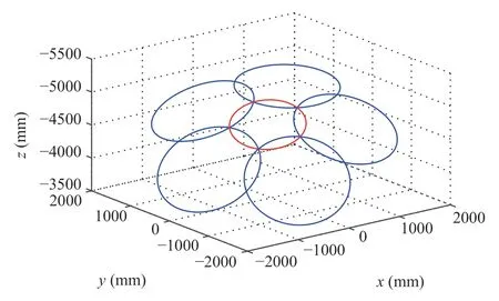
Figure 10 Envelope circle model

Figure 11 Spatial geometry model of expandable antenna
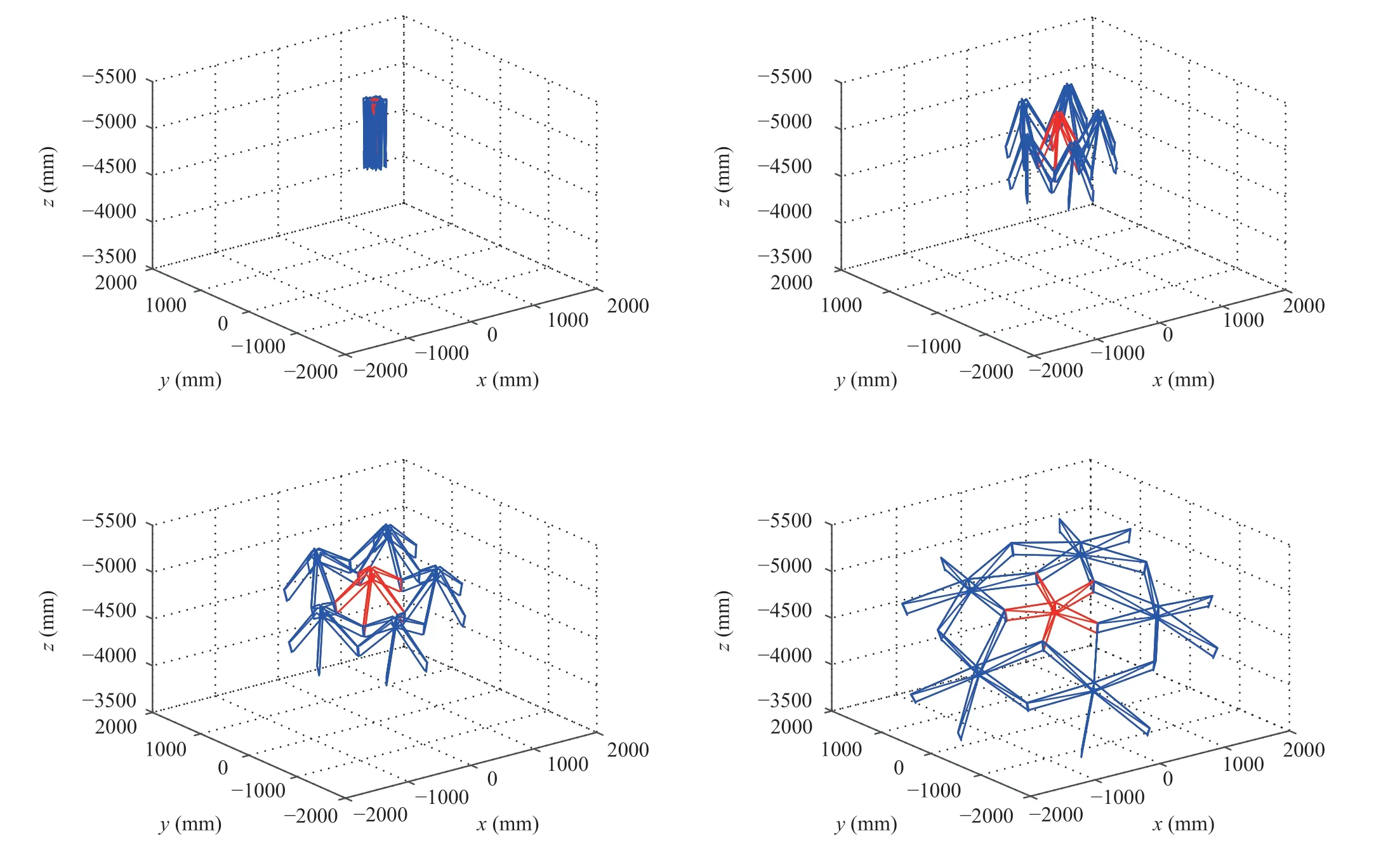
Figure 12 Expansion process simulation
6 CONCLUSIONS
In this paper,a new deployable antenna structure is proposed,and the spatial geometric model and kinematic model of the modular deployable antenna were established.The model was verified by MATLAB software,and the main conclusions are as follows:
1) A deployable antenna structure composed of hexagonal prism and pentagonal prism modules is feasible.The kinematics numerical simulation shows that the mechanism can realize multi-module linkage,and each module can realize close connection in the process of movement.
2) The relative dimensions of the pentagonal prism module and the hexagonal prism module can be selected flexibly,and they do not need to be unified.This feature has great convenience for the popularization and application of the deployable antenna in many fields,and also provides a reference scheme for the engineering application of a spatial deployable antenna.
3) The spatial geometry modeling and kinematic modeling methods proposed in this paper have strong universality,and provide reference for the research of other modular deployable antenna structures.

- Aerospace China的其它文章
- Artist’s Concept of Tianwen 1’s Brake and Captured by Mars
- Acoustic and Vibration Environment Prediction Technology of Instrument Cabin Based on Multi-Source Data
- Kinetic Laws of Heating Initiated Reactions for Materials in Aerospace Applications
- Design of Optical System for Small Long-Life Star Sensor
- In-situ Lunar Penetrating Radar Experiments on the Moon of CE-3 and CE-4 Missions
- Principle Prototype of a Recovery Launch Vehicle with Vertical Take-Off and Landing