
Principle Prototype of a Recovery Launch Vehicle with Vertical Take-Off and Landing
2022-01-18 00:40:04YANGHaoliangWANGYingchengWUWeipingLIANJieMAYuhaiSUNZhichaoYANGYiqiang
Aerospace China 2021年3期
YANG Haoliang,WANG Yingcheng,WU Weiping,LIAN Jie,MA Yuhai,SUN Zhichao,YANG Yiqiang
1 Beijing Zhongke Aerospace Exploration Technology Co.Ltd.,Beijing 100176
2 Institute of Mechanics,CAS,Beijing 100190
Abstract:In the recovery process of the reusable rocket with vertical take-off and landing,it has to go through the active control process,such as power drop,hover and vertical landing.The key technology lies in the development of high-precision vertical recovery control algorithm.Therefore,a vertical take-off and landing reusable launch vehicle prototype is developed to verify the rationality of the flight control algorithm of rocket vertical recovery.The vertical take-off and landing reusable launch vehicle prototype is 0.45 m long,0.45 m wide,0.6 m high,and has 23 kg take-off weight with a maximum thrust of 400 N jet engine as the power plant,through four gas rudders to achieve the aircraft pitch and yaw and roll-on control.The prototype focuses on the verification of the guidance and control algorithm of the vertical recovery algorithm.Therefore,it is equipped with the vector control capability,avionics and measurement system similar to that of the vertical recovery rocket.The prototype can be used for verification of the flight control algorithm.
Key words:VTVL,reusable rockets,guidance and control
1 INTRODUCTION
At present,the vertical recovery technology of launch vehicles is a new development trend in the world’s aerospace industry.Generally speaking,rocket vertical recovery technology can not only reduce the cost of rocket launches,but also break through the constraints of production capacity in nature.In turn,the rocket can realize low-cost and flight-oriented.Both the SpaceX Falcon 9 rocket and the Blue Origin New Shepard rocket have basically realized the first-stage vertical recovery technology of the rocket.This fully verified the feasibility and economic value of the vertical recovery technology.And,at the same time,this has also triggered a new upsurge in the research of the vertical recovery technology of launch vehicles around the world.
One of the key technologies of the vertical recovery technology of launch vehicles is the verification of flight control algorithms.When the algorithm design is completed,the flight verification needs to be carried out again on the physical platform.At present,while researching and developing vertical recovery algorithms at home and abroad,they will also study the prototype of the vertical take-off and landing principle and use it as an early flight control algorithm development platform.This can realize the verification of the control algorithm,avionics,and landing index of the adjustable thrust liquid launch vehicle.On this basis,it can also provide important test data support for the subsequent vertical recovery of the launch vehicle.For example:the EAGLE vertical take-off and landing vehicle developed by the German Aerospace Agency.It mainly uses jet engines as power plants.The pitch and yaw control are mainly carried out through two gas rudders,and the air-conditioning RCS is used to realize the roll-on control.The project mainly needs to fully complete the development and flight verification in 2017.
It can be seen that in the process of realizing the vertical recovery technology of launch vehicles,a small,low-cost prototype of the vertical take-off and landing principle has been developed.This has great advantages for the rapid iteration and verification of vertical recovery flight control algorithms and lowcost avionics system solutions.
This research will focus on the overall system scheme,ground test process and flight demonstration verification of the vertical take-off and landing principle prototype of the launch vehicle developed by Beijing Zhongke Aerospace Technology Co.,Ltd.
2 PROTOTYPE SYSTEM SCHEME OF LAUNCH VEHICLE VERTICAL TAKE-OFF AND LANDING PRINCIPLE
2.1 Overview
The prototype of the launch vehicle vertical take-off and landing principle is shown in Figure 3.It mainly includes six parts:main structure system,landing buffer system,storage tank and fuel supply system,gas rudder control actuator system,navigation and guidance control system and software system.
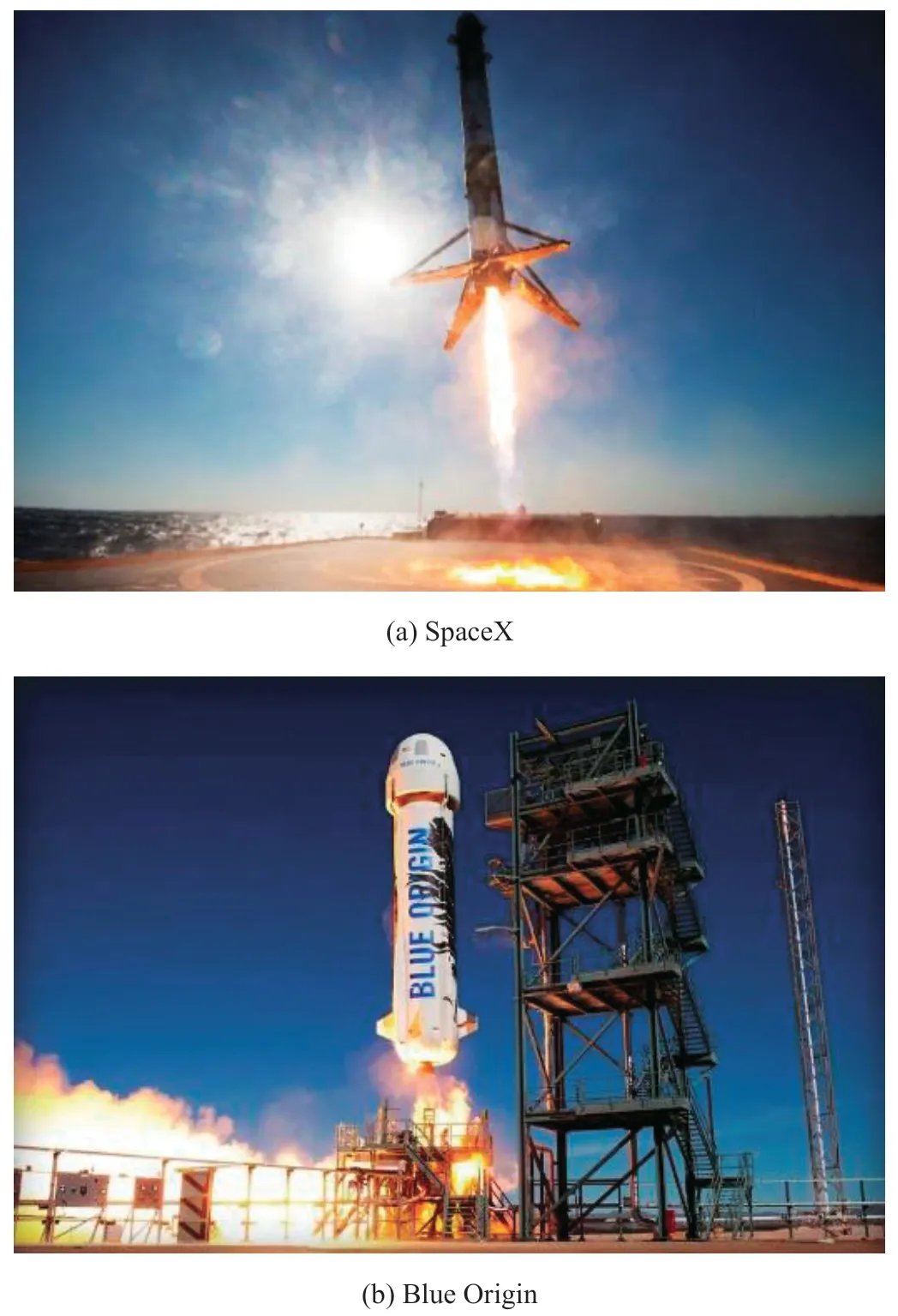
Figure 1 Vertical recovery rockets

Figure 2 EAGLE
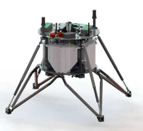
Figure 3 Prototype of launch vehicle vertical take-off and landing principle
2.2 Main Structure System
The main structure of the prototype of the launch vehicle vertical take-off and landing principle is shown in Figure 4.It is mainly composed of six 6 mm-thick 3K carbon fiber structures assembled through customized connectors.Among them,the equipment mounting plate is placed at the top.The tank mounting plate is placed at the bottom end.The upper and lower plates are mainly supported by four main bearing plates.Among them,the equipment mounting board is mainly designed with reasonable equipment mounting holes.The installation hole of the storage box is reserved on the installation plate of the storage box.In addition to the necessary mounting holes for the main bearing structure,the structure is optimized for weight reduction based on finite element simulation,and a number of weight reduction holes are designed on this basis.
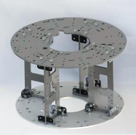
Figure 4 Schematic diagram of the main structure of the prototype
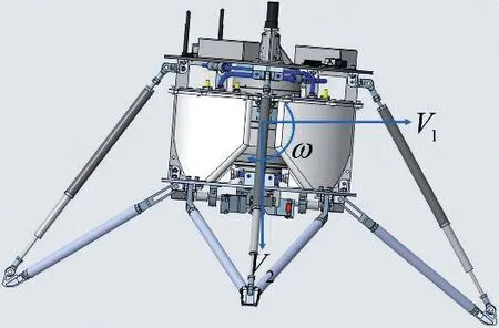
Figure 5 Schematic diagram of the landing stability of the prototype of the launch vehicle vertical take-off and landing principle
2.3 Landing Buffer System
Generally speaking,the landing system design of the launch vehicle vertical take-off and landing principle prototype must be consistent with the design method of the real launch vehicle.It adopts four-legged rocker landing buffer configuration,whose parameters are determined by the landing stability.In addition,the method of determination is mainly as follows:without considering buffer energy absorption,shortening and sideslip,according to the launch vehicle vertical take-off and landing principle,the initial kinetic energy of the prototype when landing and the potential energy increased by the critical condition of overturning are two factors to calculate the landing stability.That is to say,at landing,the horizontal velocity,sinking velocity,and rotation angular velocity of the prototype of the launch vehicle vertical take-off and landing principle are presented asV
,V
,andω
respectively,which should all be satisfied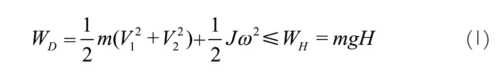
m
is the mass at the moment of landing of the prototype of the launch vehicle vertical take-off and landing principle;J
is the moment of inertia;H
is the height at which the center of mass rises at the critical moment.Figure 6 shows that when the quadruped rocker landing buffer configuration overturns,the center of mass should leave the projection circle area of radiusL
.DefineL
as the stable radius of the prototype landing system of the launch vehicle vertical take-off and landing principle.This parameter will also directly affect the design of the landing configuration of the structure.Draw a schematic diagram of the critical overturning state according to the landing parameters (as shown in Figure 6(b)).In addition,the rising height of the center of mass can be obtained from the Equation (2):

Figure 6 The stable radius of the prototype landing system of the launch vehicle vertical take-off and landing principle
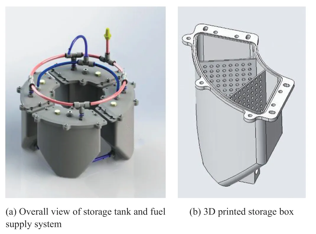
Figure 7 The storage tank and fuel supply system of the launch vehicle vertical take-off and landing principle prototype
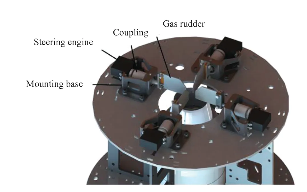
Figure 8 The gas rudder control actuator system of the launch vehicle vertical take-off and landing principle prototype
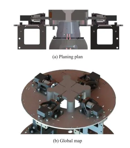
Figure 9 The assembly tooling of the control actuator system of the prototype gas rudder of the vertical takeoff and landing principle of the launch vehicle
m
.C
,K
are the equivalent damping and equivalent stiffness of the landing buffer mechanism,respectively.V
is the sinking speed (lateral speed,rotation around the center of mass,and attitude deviation are not considered in the simplified processing),andl
is the landing buffer stroke (equivalent longitudinal stroke).Among them,it is assumed that:a buffer is stable without bumping,and the buffering process is assumed to be uniform.According to the energy theorem:
At the moment when the buffer compression stroke of the launch vehicle vertical take-off and landing principle prototype is at its maximum,its recovery rocket has the highest overload factor,namely:

N
is the maximum allowable overload factor of the rocket (the design value is usually not greater than 5).m
is the mass of the rocket body of the vertical take-off and landing principle prototype of the launch.
Therefore,the simultaneous Equations (4) and (5) can obtain suitable damping parameters.
2.4 Storage Tank and Fuel Supply System
The prototype of the vertical take-off and landing principle of the launch vehicle mainly uses a jet engine with a maximum thrust of 400 N at sea level.Among them,the fuel of the engine is aviation kerosene.During the engnine working,fuel is pumped into the engine mainly through the built-in pump system.To this end,a set of storage tank and fuel supply system was developed for the prototype of the launch vehicle vertical take-off and landing principle.The main body of the system is four 3D printed photosensitive resin storage tanks.They are arranged symmetrically.The bottom of the storage tanks are mainly connected by connecting pipelines to realize the integration of the four storage tanks.In addition,the top of the tank is connected by the balance gas path to achieve pressure balance between the inside and outside of the tank.This can avoid negative pressure during flight.In addition,the oil outlet pipeline together with two symmetrical storage tanks and the engine.
Based on this,in order to prevent the vertical take-off and landing principle prototype of the launch vehicle from eventually interfering with the flight due to the sloshing of the liquid during the flight,many anti-shake damping plates are specially designed inside the 3D storage tank.
2.5 The Control Actuator System of the Gas Rudder
The prototype of the vertical take-off and landing principle of the launch vehicle mainly uses four gas rudders to control the actuator to realize the control of pitch,yaw and roll-on.The main components of the gas rudder control actuator system are gas rudders,steering gears,mounting bases and couplings,and ceramic bearings.Among them,the gas rudders adopt high temperature alloy GH4169.After mechanical processing,they can meet the thermal and strength requirements.And through the sample to carry out the mechanical characteristic test,it can be further confirmed to meet the requirements of the mechanical conditions.The cork between the superalloy GH4169 rudder surface and the shaft is mainly used as a thermal insulation layer.Ceramic bearings are used as temperature-resistant bearings to form the entire rudder system that is lightweight,load-bearing,heat-resistant,and transmission.
The relationship between the rudder deflection angle of the gas rudder and the attitude angle of the launch vehicle vertical take-off and landing principle prototype is mainly shown in the Equation as follows.
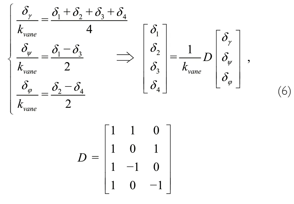
δ
,δ
,δ
,δ
are the rudder deflection angles of the four gas rudders.δ
,δ
,δ
are the pitch,yaw and roll angles of the launch vehicle vertical take-off and landing principle prototype,andR
is the equivalent thrust vector coefficient of the gas rudder.In order to fully ensure that the gas rudder control actuator of the vertical take-off and landing principle prototype of the launch vehicle can be installed correctly,special assembly tooling is specially designed,as shown in Figure 9.It is mainly based on the tank mounting plate of the launch vehicle vertical take-off and landing principle prototype.It is ensured that the initial position of the gas rudder can be perpendicular to the installation reference plane,and the thrust of its engine can pass its geometric axis first.
2.6 Navigation and Guidance Control System
The navigation and guidance control system mainly includes:flight controller,inertial unit IMU,battery,altimeter,digital transmission equipment,engine.The avionics system connection diagram is shown in Figure 10.
The inertial measurement device mainly adopts a higher precision MEMS inertial group and uses GNSS/RTK as the main positioning device.Its initial positioning uses GNSS calibration.The differential satellite navigation equipments are shown in Figure 11.
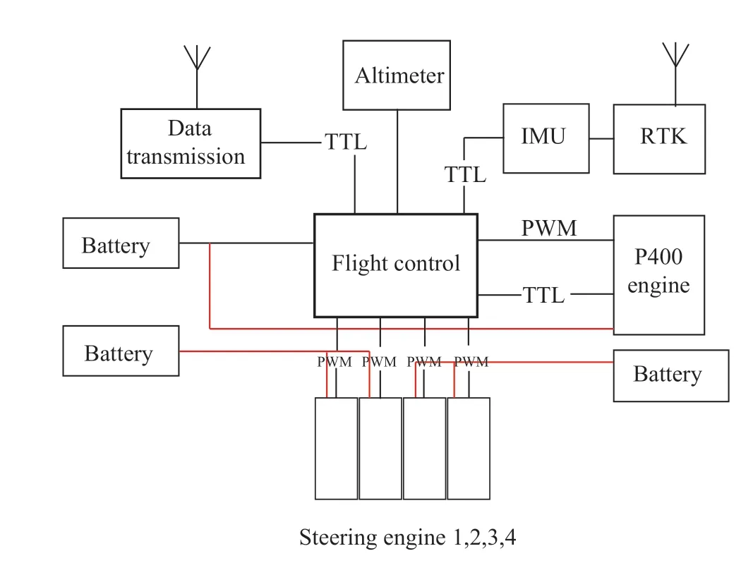
Figure 10 The connection diagram of the avionics system of the prototype of the launch vehicle vertical take-off and landing principle
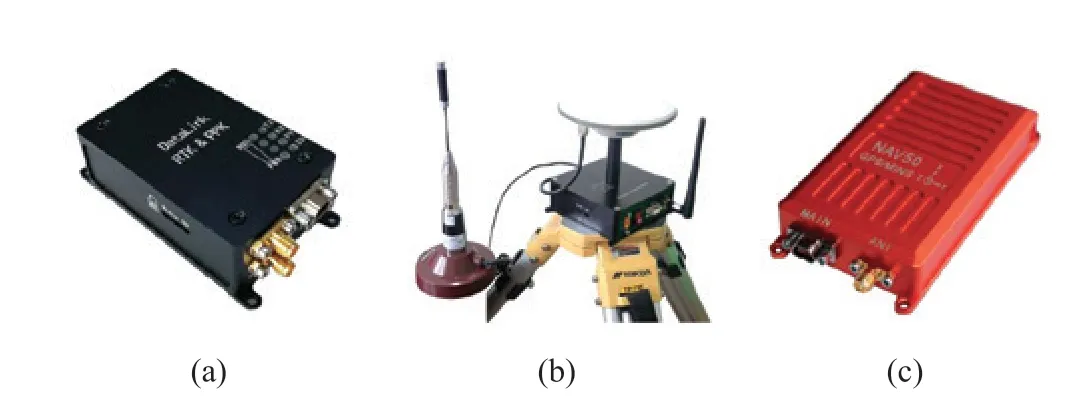
Figure 11 Differential satellite navigation and inertial group equipments (a) Differential satellite navigation GD20 module;(b) Physical map of RTK differential positioning ground reference station;(c) Integrated navigation equipment NAV50
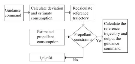
Figure 12 Flow chart of iterative guidance control
In addition,its integrated navigation mainly uses the methods of inertial recursion and GPS update,which can fully meet the needs of navigation and positioning.The initial alignment mainly uses the GNSS dual antenna orientation,and also uses the initial alignment information of the magnetic compass as a backup.Among them,the integrated navigation adopts the NAV50 series products of Chuangheng Technology.The NAV series GPS/MINS integrated navigation system integrates a three-axis gyroscope,a three-axis accelerometer,a three-axis magnetic field meter,a GPS receiving module,a barometric altimeter and other micro sensors.In addition,it uses the built-in improved extended Kalman filter algorithm (EKF) for information fusion.It can effectively reduce the influence of carrier maneuvering,vibration,environmental temperature and electromagnetic interference,and provide complete and reliable three-dimensional position,three-axis attitude,three-axis speed,three-axis acceleration and other information up to 200 Hz,make it fully used for navigation,control and dynamic measurement.
The prototype of the launch vehicle vertical take-off and landing principle is mainly used to verify different kinds of guidance and control strategies.Taking iterative guidance control as an example,the method of trajectory tracking guidance is as follows:calculate the deviation between the current position parameter and the current reference trajectory,and estimate the propellant consumption based on the deviation.Calculate and adjust the reference trajectory according to the remaining full movement time,current position parameters,and landing target position parameters.If the constraints of the propellant are not satisfied,continue to adjust the remaining full motion time.And calculate and adjust the reference trajectory according to the remaining full motion time.Then estimate the propellant consumption required to adjust the reference trajectory.This reciprocates until the constraint conditions of the propellant are satisfied and the control is stabilized.It is the final completion of the test flight.
2.7 Software System
The prototype of the launch vehicle vertical take-off and landing principle mainly uses the RT-linux interface as a real-time operating system for flight control software.In view of the task calculation requirements required by the principle verification aircraft,in order to deterministically ensure that it can meet the time requirements,the current soft real-time system is mainly used to realize the development and operation of flight control software.It can balance development efficiency and flight requirements.
3 GROUND TEST SYSTEM
3.1 Centroid Measurement and Trim System
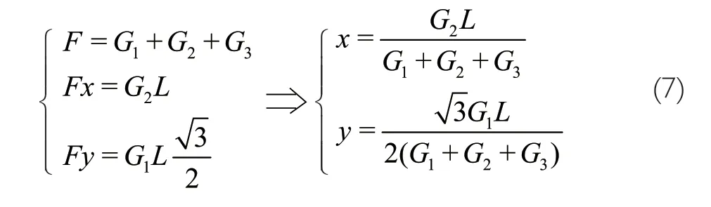
In order to reduce the displacement of the center of mass caused by the assembly error of the prototype of the launch vehicle vertical take-off and landing principle.Therefore,a set of centroid measurement and trim system as shown in Figure 13(a)has been developed.The system is mainly composed of a horizontal seat and a three-point gravity measurement system.The coordinates of these three measurement points are shown in Figure 13(b).The coordinates of mass center can be obtained mainly by measuring the distanceL
between the three gravity pointsG
,G
andG
and the three measuring points.It is shown in the Equation(7).Furthermore,after obtaining the precise coordinates of the center of mass,the center of mass can be trimmed by adjusting the mass or adding a counterweight.Furthermore,it can be ensured that the deviation between the center of mass and the thrust line is controlled within ±2.5 mm.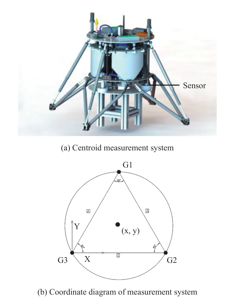
Figure 13 Centroid measurement and trim system
3.2 Thrust Test System
The power system of the launch vehicle vertical take-off and landing principle prototype is mainly a jet engine with a maximum thrust of 400 N.Its pitch,yaw and roll are mainly realized by the four-piece split gas rudder differential control.The thrust of the engine is not only used to counter gravity,but also provides a control vector through the gas rudder.This will inevitably cause the loss of thrust vector.In addition,the thrust loss model requires not only CFD simulations,but also thrust test experiments for verification.
Thrust test data is very critical,due to the thrust margin of the prototype of the launch vehicle vertical take-off and landing principle is relatively small.Affected by the temperature environment,the test data is directly related to the accuracy of the control system model.If the test is improper,it may even cause the flight test to fail.Therefore,the vertical take-off and landing principle prototype of the launch vehicle designed a thrust test system as shown in Figure 14.In detail,the main components of the system include the thrust sensor and the horizontal slide.During the test,the main structure of the prototype of the launch vehicle vertical take-off and landing principle,the engine and the gas rudder actuator were placed on the test system together.The thrust output of the engine and the rudder deflection angle of the gas rudder are controlled by the program,and the thrust sensor is used to collect the thrust test curve under the ambient temperature (as shown in Figure 15).On this basis,the designed control system model is revised according to its actual thrust test curve.
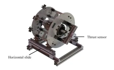
Figure 14 Thrust test system
3.3 Tethered Flight Test
The launch vehicle vertical take-off and landing principle prototype needs to carry out a tethered flight test before the official flight test is carried out.Its purpose and content include:
1) Engine anti-torque interference torque measurement,ability evaluation of rudder differential roll channel control;
2) Fine adjustment of the installation error of the engine,the deflection of the thrust line,and the lateral shift of the thrust line;
3) Carry out the hovering flight in the tethered state,and then confirm the correctness of the prototype control system model of the launch vehicle vertical take-off and landing principle.
4 FLIGHT TEST
4.1 Flight Test Procedure
The first is the preparatory work for fuel refueling and centroid testing and matching and firing;then,the flight procedure is bound to the flight controller.And after the procedure upload is completed,GNSS positioning,telemetry confirmation,engine status confirmation,and control algorithm confirmation are carried out in sequence.After confirming that the system status is correct,a take-off instruction is sent.The prototype of the launch vehicle vertical take-off and landing principle flies in accordance with its scheduled procedures.
4.2 Flight Test Results
The prototype of the vertical take-off and landing principle of the carrier rocket completed the flight test on March 21,2021 at Haiyang Dongfang Aerospace Port in Yantai City,Shandong Province,China with a complete success,as shown in Figure 17.The test verified the effectiveness of the prototype of the launch vehicle vertical take-off and landing principle as a flight control algorithm verification platform,which will be applied to the verification of the vertical take-off and landing flight control algorithm of the launch vehicle in the later period.
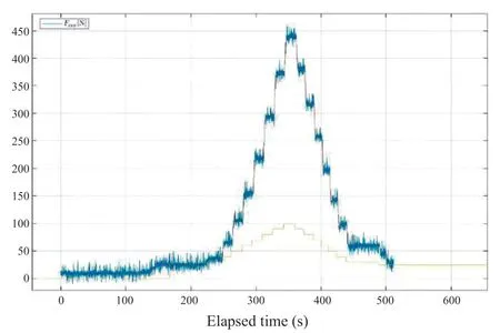
Figure 15 Results of thrust test

Figure 16 Tethered flight test site

Figure 17 Flight test site
5 CONCLUSION
This article fully summarizes the system scheme,development process and flight test results of the launch vehicle vertical take-off and landing principle prototype.The flight test further verified the correctness of the principle prototype system scheme and its effectiveness as a flight control algorithm verification platform.The prototype will be further applied to the verification of the vertical take-off and landing flight control algorithm of the launch vehicle.

- Aerospace China的其它文章
- Artist’s Concept of Tianwen 1’s Brake and Captured by Mars
- Acoustic and Vibration Environment Prediction Technology of Instrument Cabin Based on Multi-Source Data
- Kinetic Laws of Heating Initiated Reactions for Materials in Aerospace Applications
- Design and Kinematics Analysis of Support Structure for Multi-Configuration Rigid-Flexible Coupled Modular Deployable Antenna
- Design of Optical System for Small Long-Life Star Sensor
- In-situ Lunar Penetrating Radar Experiments on the Moon of CE-3 and CE-4 Missions