基于MEMS工艺的起爆序列设计研究
解瑞珍陈建华刘 卫刘 兰任小明薛 艳
(应用物理化学重点实验室,陕西应用物理化学研究所,陕西 西安 710061)
The soldier lethality will be significantly enhance by making safer and more reliable weapons affordable,with less weight,and larger warheads or improved guidance or target sensing.Micro-electro-mechanical systems(MEMS)technology is an important way to miniaturize fuze.Its smaller characteristic size provides the advantage of reducing mass and volume.The U.S.Army Research,Development,and Engineering Command(RDECOM)-Armament Research and Engineering Center(ARDEC)is applying MEMS technology to produce significantly smaller,safer and less expensive safety and arming(S&A)devices,MEMS detonators for munition fuzing systems than have been possible before[1-4].
The MEMS-based S&A technology can apply not only to miniature,medium-and large-caliber munitions,but also to mortars,submunitions and rocket.The typical MEMS safety and arming device reported in the American fuze annual meeting is mainly composed of cap chip,MEMS chip,flyer,base chip,secondary lead,booster charge.Initiator fabricated onto the cap chip-vaporizing metal foil bridge,Pressed silver azide pellet assembled with the MEMS S&A chip,flyer installed between MEMS chip and base chip.In safe position,silver azide is out-of-line with initiator and secondary lead to realize physical isolation.In the arming state,silver azide is in-line with initiator and secondary lead to form a detonation[5-9].
The MEMS-based explosive train is designed in this paper which mainly includes micro detonator,S&A device and booster etc.The ideal design parameters are obtained by optimizing the parameters of the primary explosive charge,flyer thickness and accelerating chamber diameter.
1 MEMS-based Explosive Train Architecture
The goal of micro initiation train design is to simplify the charge structure,reduce the axial size.Because the size is very small,usually a transfer charge embedded in MEMS arming slider to realize detonation energy amplification and reliable transmission.However,the slider thickness of MEMS S&A is generally less than 0.5mm,and it is a movable part from a position that is out-of-line with all other explosive components,to a position where it is in-line with them and completes the explosive train.it is difficult to complete the high-density charge,the charge has accidental explosion hazards under the condition of high overload.Canceling the charge on the S&A device is another important goal.the structural diagram of the explosive train designed is shown in Figure 1,which is mainly composed of control circuit,MEMS micro detonator,flyer,S&A device,booster.The cavity through the slider is used as the acceleration chamber of flyer,which can effectively utilize the structural advantages to simplify the charge structure,reduce the charge and the axial size.

Fig.1 Structural diagram of the explosive train
The function process of the explosive train is showed in figure2.in safe position,the MEMS detonator and booster are separated by the arming slider to realize physical isolation.In the armed position,the slider completes the design displacement,and the detonation channel is formed,the MEMS detonator,booster cavity and booster is in-line.MEMS detonator cuts and drives the flyer to accelerate through the acceleration chamber,and the high-speed flyer impacts and detonates the booster.

Fig.2 Structure diagram of the detonating train
CL-20 based booster is selected because of high impact sensitivity,maximum detonation velocity and pressure of CL-20 can reach 9.5 km/s-9.6 km/s and 43 GPa-44 GPa,respectively.The standard enthalpy of formation is about 980 kJ·kg,which is 9.2%higher than HMX,7%higher in density,10%-15%higher in energy output than HMX,and the shock wave sensitivity of CL-20 is higher[10-11].The charge size isΦ3.0 mm×(H)3.0 mm,and the charge density is 1.8 g/cm3,which is 90%of its maximum theoretical density.
1.1 MEMS detonator

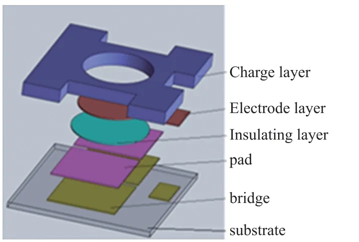
Fig.3 Structure sketch map of MEMS detonator
The structure diagram of MEMS detonator is shown in Figure 3,which is mainly composed of substrate,firing element fabricated on the substrate,insulation layer,charge electrode,charging cavity layer,primary explosive, etc. The acceleration chambere firing element[12]composed Ni-Cr bridge and Cu pad,it’s function is energy conversion,convert electric energy into heat energy and initiate primary explosive.The primary explosive uses porous copper azide.
The process of the fabrication is shown in Figure 4.The firing element was firstly fabricated on the substrate by sputtering,photolithography,wet etching and so on.The second step,sputtering or PECVD process is used to complete the insulation layer,and different graphic processes are selected according to different insulating materials.The third step,the electrode was fabricated on the insulating layer by sputtering,photolithography,wet etching etc.The fourth step,the groove was fabricated for embedding the firing element on the double-polished silicon substrate by photolithography,wet etching etc.The fifth step,the charge cavity was fabricated on another top of double-polished silicon substrate by sputtering,photolithography,wet etching and deep reactive ion etching.The sixth step,the glass substrate and silicon substrate was bonded together by chip-chip anodic bonding methods.The seventh step,energetic material was loaded into the cavity by in situ charge technology[13].

Fig.4 The process flow of the fabrication of MEMS detonator
1.2 MEMS-based S&A
To perform the safety and arming functions of a S&A device,the MEMS-based S&A must incorporate at least two independent safety locks,each of which can prevent unintentional arming of the S&A.Figure 5 shows the basic design of the inertial-mechanical logic for a MEMS S&A device.The MEMS S&A consists of a setback slider with pre-tensioned spring,a setback lock on the arming slider that the setback slider can release,an arming slider,and a command actuator lock.The arming slider controls the position of acceleration chamber that is held out-of-line with the explosive train until arming occurs.

Fig.5 Structure sketch of MEMS S&A
aunch setback acceleration drives the setback slider aftward against spring tension,move to design position and latch down,disengages the setback lock from the arming slider.Centrifugal acceleration drives the arming slider to the right against spring tension,until stopped temporarily by the command lock.After safe separation of the weapon from the gun,a pyrotechnically driven command lock,out of engagement with the arming slider.
Traditional wafer-based LIGA uses synchrotron radiation(X-Ray)and a patterned absorber mask to expose a thick PMMA(poly-methyl-methacrylate)resist,which is subsequently developed and plated into,then planarized and released to form polished,micro-resolution parts.This fabrication process,however,is highly specialized in that it requires a high-powered,collimated X-ray source for mold formation.In addition,the number of these source is quite limited and the cost of building new ones makes it prohibitive for the mass production of HAR MEMS S&A devices.UV-LIGA is inexpensive compared to X-ray LIGA,and recent advance in the technology are yielding single-and multi-layer techniques to produce high-accuracy,vertical side-wall parts of extremely high quality.PMIM creates molded metal parts using a nano-particle slurry mixture injected into a LIGA-produced reusable precision micro-mold master.So UV-LIGA process is used in the production of S&A.
2 Parameter optimization and performance testing of explosive train
2.1 Parameter optimization of explosive train
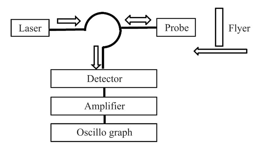
The key parameters for the design of MEMS-based explosive train include acceleration chamber through the S&A,flyer thickness,porous copper azide charge parameters,ignition conditions,etc.In this paper,PDV is used to test the velocity of flyer and to optimize the design parameters The principle of PDV speed measurement is shown in Fig.6.The light reflected from the surface of the laser probe is reflected back to the system as the reference light;the light reflected from the flyer is used as the signal light.After the interference between the two reflected lights,the differential interference signal of the reference light and the signal light is detected by using the square detection characteristic of the detector,and the photoelectric conversion is realized.After the electric signal is amplified,it is collected by the oscilloscope The velocity history of flyer is obtained by FFT.

Fig.6 Schematic diagram of PDV speed measurement
The test system is composed of DC power supply,ignition control circuit,delay pulse generator,optical fiber probe,photon doppler velocimeter,digital oscilloscope,explosion tank,etc.The resolution of DC power supply is 0.01 V,the charging resistance of ignition circuit is 5 000Ω,the firing capacitor is 100μF tantalum capacitor,and the discharge switch is mercury switch.The speed measurement range is 0-9 000 m/s,the time resolution of the recording system is less than 50 ps,and the speed resolution is less than 5 m/s.
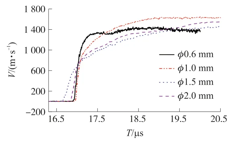
When the parameters of accelerating chamber,flyer,charge density and height remain unchanged,the speed of flyer driven by MEMS detonator with charge diameter of 0.6 mm,1.0 mm,1.5 mm and 2.0 mm is tested.The test results are shown in Figure 7.
It can be seen from Figure 7 that under the same charge density,the speed of flyer driven by MEMS detonator with charge diameter of 1.0 mm is significantly higher than that of 0.6 mm,and that of MEMS detonator with charge diameter of 1.0 mm is equivalent to that of 1.5 mm,slightly higher than that of 2.0 mm.According to the requirements of miniaturization design,the optimal charge diameter is 1.0 mm MEMS detonator.

Fig.7 Speed test results of flyer with different charge diameter
When the parameters of flyer and charge remain unchanged,the speed of flyer driven by MEMS detonator is tested with accelerating chamber diameter of 1.0 mm,1.5 mm and 2.0 mm.The test results are shown in Fig.8.

Fig.8 Speed test results of flyer with different barrier diameter
It can be seen from Figure 8 that under the same conditions of charge diameter,flyer thickness and firing conditions,when the accelerating chamber diameter is 1.0 mm and 1.5 mm,the flyer speed is equal.When the accelerating chamber diameter is 1.0 mm,the flyer acceleration is greater and the time to reach the maximum speed is shorter.When the diameter of accelerating chamber is 2.0 mm,the speed of flyer is slightly lower than that of 1.0 mm and 1.5 mm.As the diameter of accelerating chamber is larger,the kinetic energy is relatively larger,and whether it is more favorable for the next charge detonation.The detonation performance of the train is tested,the results are shown in Table1.

Table 1 Performance test results of different accelerating chamber
It can be seen from table 1 that the diameter of the accelerating chamber isΦ1.0 mm better than that of the Φ1.5 mm.Combined with the test results in Fig.8,Φ1.0 mm×(H)1.0 mm is selected as the size of the accelerating chamber.
The velocity of flyer with thickness of 10μm,20μm,30μm,40μm and 50μm is tested under the other condition is same.The test results are shown in Figure 9.
It can be seen from Figure 9 that the thicker the flyer,the smaller the flyer speed.As the thicker the flyer,the greater the impact energy.The detonation transmission performance was tested when the thickness of flyer is different.The test results are shown in Table 2.

Fig.9 Speed test results of flyer with different thickness

Table 2 Test results of different thick flyer
It can be seen from table 2 that when the thickness of flyer is 30μm,the output performance of train is better than 50μm and 10μm.Think of the test results in Figure 9,30μm is selected as the thickness of flyer.
The test results of the speed of flyer driven by MEMS detonator under different firing voltage are shown in Table 3.

Table 3 Test results of different firing voltage
It can be seen from table 3 that with the increase of firing voltage,the flyer speed first increases and then decreases,and the firing voltage is selected as 15 V.
2.2 Performance testing of MEMS-based Explosive Train
The explosive train is fabricated,and the process is shown in Figure10,the control circuit is fabricated based on IC process,wire bonding process is used to integration of MEMS detonator and control circuit;insitu charging process is used to the charging of MEMS detonator,The UV-LIGA process is used to the fabrication of S&A.
According to the optimization results of explosive train parameters,the diameter of the charge is 1.0 mm,the size of the acceleration chamber isφ1.0 mm×(H)1.0 mm,and the thickness of the flyer is 30 micrometer,the charge density of MEMS detonator charge is 1.5 g/cm3,1.8 g/cm3and 2.1 g/cm3respectively.Then the detonation performance of the train was tested accord to GJB5309.17-2004(K)test method of initiators&pyrotechnics:determining of axial output,method of aluminum dent,the results are shown in Table 4.

Table 4 Performance test results of different charge density

Fig.10 Fabrication flow chart of explosive train
It can be seen from the test results in Table 4 that the explosive train achieves reliable detonation transmission,when the charge density of porous copper azide is 2.1 g/cm3.Photos of the train and identification block after test is shown in Figure 11.

Fig.11 Photo of the train and identification block
3 Conclusions
The MEMS-based explosive train exploits the design and Parameter optimization of MEMS detonator MEMS S&A,micro-scale initiation train to achieve higher reliability,improved safety,lower volume and the potential for lower cost for munition fuzes.
Through the optimization of the key parameters,the MEMS-based explosive train achieves reliable detonation transmission when copper azide charge diameter is 1.0 mm,charge density is 2.1 g/cm3,size of accelerating chamber isΦ1.0 mm×(H)1.0 mm through the S&A,thickness of flyer is 30μm.
Compared with the MEMS Micro initiation system reported in the United States[4],the design of the explosive train cancels the charge on the slider of the S&A.The charge structure is simpler,the integration compatibility with other devices is better.
——喜迎十九大 追赶超越在陕西

