A simulation study of protons heated by left/right-handed Alfvén waves generated by electromagnetic proton–proton instability
Jiansheng YAO (姚建生) , Yingkui ZHAO (赵英奎), Difa YE (叶地发),Yi LI (李毅), Lihui CHAI (柴立晖) and Jicheng SUN (孙继承)
1Institute of Applied Physics and Computational Mathematics,Beijing 100088,People’s Republic of China
2 CAS Key Lab of Geospace Environment,School of Earth and Space Sciences,University of Science and Technology of China, Hefei 230026, People’s Republic of China
3 Key Laboratory of Earth and Planetary Physics,Institute of Geology and Geophysics,Chinese Academy of Sciences, Beijing 100029, People’s Republic of China
4 Key Laboratory of Polar Science,Ministry of Natural Resources,Shanghai 200020,People’s Republic of China
5 MNR Key Laboratory for Polar Science, Polar Research Institute of China, Shanghai 200136, People’s Republic of China
Abstract Most protons in the solar wind belong to one of two different populations, the less dense beam protons and the denser core protons.The beam protons, with a velocity of (1–2) VA (VA is the local Alfvén speed),always drift relative to the core protons;this kind of distribution is unstable and stimulates several kinds of wave mode.In this study, using a 2D hybrid simulation model,we find that the original right-handed elliptically polarized Alfvén waves become linearly polarized, and eventually become right-handed and circularly polarized.Given that linearly polarized waves are a superposition of left-handed and right-handed waves,cyclotron resonance in the right-handed/left-handed component heats beam/core protons perpendicularly.The resonance between beam protons and right-handed polarized waves is stronger when the beam relative density is lower, resulting in more dramatic perpendicular heating of beam protons,whereas the situation is reversed when the beam relative density is larger.
Keywords: proton/proton instability, hybrid simulation, Alfvén waves
1.Introduction
In situmeasurements of the solar wind, especially for fast solar wind with a typical flow speedvSW>600 km s−1,have shown that the distribution of solar-wind protons is very different from a Maxwellian distribution [1–6].Two significantly different components populate proton distributions:the less-dense proton population (always referred to as the beam population)drifts with a velocity of(1–2)VA(VAis the local Alfvén speed) relative to the more dense population(called the core population) and parallel to the ambient magnetic fieldB0.Recently, the successful launch of contemporary inner heliospheric missions, i.e., NASA’s Parker Solar Probe,and ESA’s Solar Orbiter,has sparked a research boom on the topic of the fast solar wind [7–9].Using linear theory, previous studies [10–14] have proved that two types of wave mode are unstable in the ion-beam system: magnetosonic instability with a maximum growth rate along the ambient magnetic field and the Alfvén mode that propagates obliquely toB0.Further studies by Daughton and Gary [12]have shown that, compared with the magnetosonic wave, the Alfvén mode has a larger growth rate and a lower threshold at a sufficiently large beam density and a sufficiently small core plasma beta (the ratio of thermal pressure to magnetic pressure).
According to their differences in ion type, electromagnetic ion–ion instabilities can be roughly classified into electromagnetic alpha–proton [15, 16], heavy-ion–proton[17],and electromagnetic proton–proton instabilities[18–22].An investigation into the electromagnetic alpha–proton instability showed that during nonlinear evolution, the wavenumber,frequency,and propagation angle of the oblique Alfvén mode all drift to smaller values.A study of heavy-ion–proton instability [17] revealed that the velocity threshold of the right-handed polarized ion–ion resonant instability decreases with a decrease in the gyrofrequency of the beam ions.
Research [22] into proton–proton beam instability has shown that wave parallel wavenumbers and frequencies may grow during evolution, and that protons and heavy ions are heated perpendicularly [19, 22].Furthermore, a previous study[21]found that when the proton beam relative density is high enough,the frequencies of the oblique Alfvén mode can exceed the proton gyrofrequency.Since Alfvén waves generated by electromagnetic proton–proton instability may be closely related to solar-wind heating, many researchers [19,23–27] have been devoted to studying the heating of core protons and heavy ions.In this study, we find an interesting phenomenon: beam perpendicular heating is stronger when the relative beam density is higher, while core perpendicular heating is stronger when the relative beam density is lower.Further investigation has revealed that perpendicular heating in these two situations corresponds to different polarized wave modes.
In this paper, a 2D hybrid simulation model [28–30] is applied in order to investigate the perpendicular heating of protons by left/right-handed Alfvén waves generated by electromagnetic proton–proton instability.This paper consists of four sections: the simulation model is described in section 2, the simulation results are illustrated in section 3,and the summary and discussion are presented in section 4.
2.Simulation model
A 2D hybrid simulation model is applied in this paper.In the hybrid simulation model, ions are treated as macroparticles,while electrons are treated as a massless fluid and follow the motion of ions.The simulation is performed in thex-yplane.According to observations in the solar wind [1–6], doublepeak-distributed protons consist of two components: a core population marked with the subscript ‘c’ and a less dense beam component drifting along the ambient magnetic field marked with the subscript‘b’.In the simulation,the direction of the drift velocity is along the ambient magnetic fieldB0and all along thex-axis.Initially, the core protons satisfy a Maxwellian distribution and the beam protons drift relative to the core protons with a velocityUbc=1.55VA.Previous studies have proved that electromagnetic ion–ion instability is dominant in the region with smallβcand reasonable beam velocities.Thus,in this study,the initial plasma beta for core and beam protons is set toβc=βb= 0.01and the plasma beta of electrons isβe= 0.01.Two runs with different beam relative densitiesnb/neare reported in this paper, wherene=nb+nc:run 1 usesnb/ne=0.15and run 2 usesnb/ne=0.4.These two scenarios depict situations with small and large beam relative densities, respectively.
In the simulation, the unit of length is the proton inertial length,which is defined asdi=c/ωp,wherecandωpare the speed of light and the proton plasma frequency, respectively.The unit of time is the reciprocal of the proton gyrofrequency.Therefore, the velocity is normalized todiΩp,which is equivalent to the Alfvén speedVA.The total number of grid cells isnx×ny=256 ×256and the size of each cell is 0.8di×0.8di.To guarantee the stability of the simulation,the time step is set toΔt=0.025and the electron resistive length is set toTo reduce numerical disturbance, the average proton number in each cell is 100.The periodic boundary condition is applied in this simulation.The resolutions of the wavenumber and the wave frequency are 3.927 (c/ωp)−1and 3.14,respectively.
3.Simulation results
Figures 1(a)and(b)correspond to the temperature evolutions of runs 1 and 2, respectively.Figures 1(c) and (d) show the evolutions of the beam drift velocity(displayed with red lines)and the core proton drift velocity(displayed with blue lines)for runs 1 and 2.The parallel and perpendicular temperatures are calculated following this procedure: first, we calculate the parallel temperatureand the perpendicular temperaturefor the ion speciesj(i.e., core protons and beam protons) in every grid cell (the bracket〈〉denotes an average over one grid cell),whereandkBis the Boltzmann constant; the temperatures are then averaged over all grids.Using this method, the effect of the bulk velocity at each location on the temperature can be eliminated.The beam velocity is the average velocity of the protons over all the grid cells.

Figure 1.(a)Temperature evolutions of the beam and core protons for run 1.(b)Temperature evolutions of the beam and core protons for run 2.Parallel and perpendicular temperatures are denoted by the subscripts ‘‖’ and ‘⊥’, respectively.The temperatures of the beam and core protons are denoted by the subscripts‘b’and‘c’.T0 is the initial temperature.(c)The evolution of the drift velocities of the beam(displayed with red lines)and core protons(displayed with blue lines)for run 1.(d)The evolution of the drift velocities of the beam and core protons for run 2.The black lines represent the relative drift velocities between the core and beam protons.
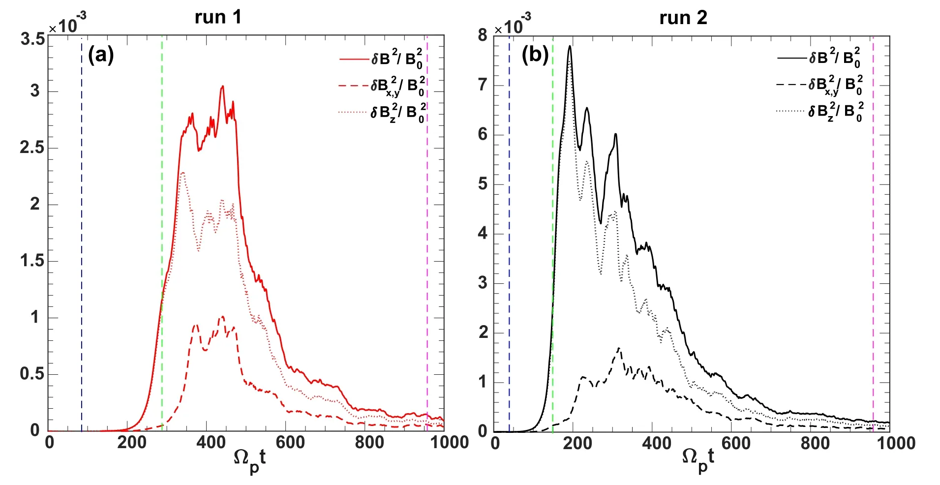
Figure 2.The evolution of the power of the disturbing magnetic fieldsδB2/ B02 (represented by solid lines),δBz/B02 (represented by dotted lines), and δBx 2 , y/B02 (represented by dashed lines, whereδB x 2 , y= δB x 2+δBy2 ) for (a) run 1 with a 15% beam relative density, and (b) run 2 with a 40% beam relative density.

Figure 3.The contours of the characteristics of the k x −ky diagram for run 1,as obtained from a fast Fourier transform (FFT)ofδBz at(a)Ω pt =80,(b)Ω p t=280,and(c)Ω p t=960,respectively.The wavevectors k=(k x, ky,0)of the dominant wave(the wave mode with the maximum power) for these three figures are (a) k=(1.05, 1.35, 0) , (b) k=(1.12, 1.08, 0) , and (c) k=( 1 .38, 1.02, 0) , respectively.

Figure 4.The contours of the characteristics of the k x −ky diagram for run 2 obtained from the fast Fourier transform (FFT) ofδBz at(a)Ω pt =40,(b)Ω p t=150,and(c)Ω p t=960.The wavevectors k=(k x, ky,0)of the dominant wave(the wave mode with the maximum amplitude) for these three figures are (a) k=(0.95, 1.12, 0) , (b) k=(1.02, 1.05, 0) , and (c) k=(1.52, 0.93, 0) , respectively.
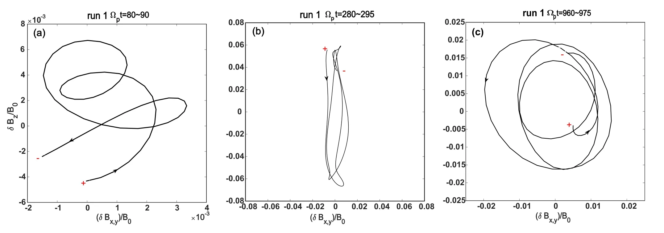
Figure 5.Hodograms in the planeδB x , y −δBz for run 1 for the intervals (a) t Ωp =40 −50,(b) t Ωp=280 −295,and (c) t Ωp=960−975.The excited waves have a right-handed elliptical polarization and then become linearly polarized;eventually,they adopt a right-handed circular polarization.Here, δBx ,y= ( − δ Bxk y + δB y k x ) /‘+’ and ‘-’ represent the start and end points, respectively.
As shown in figure 1,protons are primarily heated in the direction perpendicular to the background magnetic field at velocities between Ωpt≈200 −500and the parallel temperatures of the beam and core protons decrease during Ωpt≈200 −300and gradually rise after that.As shown in figure 1(b), the perpendicular temperatures of the core and beam protons increase at velocities between Ωpt≈100−400.It is worth noting that the perpendicular heating of beam protons is stronger than that of core protons in figure 1(a),but that the perpendicular heating of core protons is stronger in figure 1(b).This intriguing phenomenon will be studied further in the following sections.It should be emphasized that while this research focuses on the evolution of the perpendicular temperature, the complicated evolution of the parallel temperature is a fascinating problem that warrants additional examination in future work.
As proved by previous studies[19, 22],the perpendicular heating of protons is closely related to cyclotron resonance with oblique Alfvén waves excited by electromagnetic proton–proton instability.This resonant interaction between waves and protons can be described quantitatively by the resonant factor[9, 16], which is defnied asζ±=(ω−k x Uj±nΩp)/k x vjth∣∣(n=0, 1, 2...) (where the superscripts+ and – correspond to the resonances of the right- and left-handed polarized waves, respectively.Ujandvjth∣∣are the drift and parallel thermal velocities of particle speciesj,respectively).When the cyclotron resonant factor satisfies the condition∣ ∣ζ<±3,cyclotron resonance can be considered to have occurred between waves and particles,and the smaller the value of∣ζ±∣,the stronger the resonant interaction between waves and protons.Since the calculation of∣ ∣ζ±involves waves with different polarizations, we need to study the polarization of excited waves before the calculation.
A previous study [19] has demonstrated that Alfvén waves produced by electromagnetic proton–proton instability are linearly polarized during evolution.This can be represented by the evolution of the powers ofandAs illustrated in figure 2, the power of the outof-plane componentδBz2/B02is much larger than that of the in-plane componentduring Ωpt≈250 −400for run 1 (Ωpt≈150 −300for run 2).This indicates that the excited Alfvén waves have a nearly linear polarization during this period.After that,the power ofδBz2/B02decreases rapidly and approaches that ofThis indicates that the excited Alfvén waves become circularly polarized at this stage.
The evolution of the hodogram can be used to visually represent the polarization of excited waves.For waves propagating obliquely relative to the magnetic field in our simulation,the polarization of waves should be viewed in the direction of the wavevector.Considering that our simulation is performed in the −x yplane, we can directly get the wavevectork=(kx,ky,0)of the dominant wave (the wave mode with the maximum power) via a 2D fast Fourier transform(FFT)of the magnetic field.After that,the magnetic field is projected onto the plane perpendicular tok.Assuming that the wavevectorkdoes not change over a short period,the polarization of waves can be viewed in the planeδBx,y−δBz,where

The contours of the characteristics of thekx−kydiagram for run 1 obtained from the FFT at different moments is presented in figure 3.Three time periods are selected in order to study the wave polarization beforeδBz2/B02increases(tΩp=80 −90and 40–50 for run 1 and run 2,respectively),whenδBz2/B02reaches saturation (tΩp=280 −295and 150–165 for run 1 and run 2,respectively),and afterδBz2/B02decreases in figure 2(tΩp=960 −975for run 1 and run 2),respectively.The start times of these three durations are marked with vertical dashed lines in blue,green,and purple in figures 1 and 2,respectively.The wavevectorsk=(kx,ky, 0)of the dominant wave (the wave mode with the maximum power) that correspond to these three durations are =k(1.05, 1.35, 0) ,k=(1.12, 1.08, 0) ,andk=(1.38, 1.02, 0) ,respectively.Similarly, as illustrated in figure 4, we obtained the contour of characteristics of thekx−kydiagram for run 2.
The wavevectorsk=(kx,ky,0)of the dominant wave in figures 4(a)–(c) arek=(0.95, 1.12, 0) ,k=(1.02, 1.05, 0) , andk=(1.52, 0.93, 0) , respectively.By substituting a wavevector into equation (1), we can map the fluctuating magnetic field onto the plane perpendicular tok,and obtain the hodogram in the planeδBx,y−δBz.
Figures 5(a)–(c) show the hodograms in the planeδBx,y−δBzfor run 1 attΩp=80 −90,tΩp=280 −295,andtΩp=960 −975,respectively.As shown in figure 5,the amplitude ofδBzis greater than that ofδBx,yduringtΩp=80 −90,indicating that the excited waves have roughly right-handed elliptical polarization.DuringtΩp=280 −295, the amplitude ofδBzis much greater than that ofδBx,y,meaning that the excited waves become linearly polarized.Linearly polarized waves can be seen as the superposition of left-handed and right-handed polarized waves.As presented in figure 5(c), waves change to a righthanded circular polarization duringtΩp=960 −975.The polarization of the waves presented in figure 5 is compatible with what is seen in figure 2.Similarly,figures 6(a)–(c)show the evolution of the vectorδBfor run 2 in the planeδBx,y−δBzattΩp=40 −50,tΩp=150 −165,andtΩp=960 −975,respectively.The original right-handed circular waves evolve to a linear polarization, and eventually to a right-hand circular polarization.In conclusion,regardless of the beam’s relative density, initial elliptical right-handed waves gradually become linearly polarized, and ultimately take on a right-handed circular polarization.The change in polarization may be caused by changes in temperature or drift velocities; however, this interesting phenomenon is beyond the scope of this paper and warrants further investigation in future work.
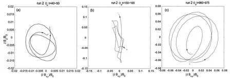
Figure 6.Hodograms in the planeδB x , y −δBz for run 2 for the intervals (a) t Ωp =40 −50,(b) t Ωp=150 −165,and (c) t Ωp=960−975.The excited waves have a right-handed elliptical polarization and then become linearly polarized;eventually,they adopt a right-handed circular polarization.Here, δBx ,y=‘+’ and ‘-’ represent the start and end points, respectively.
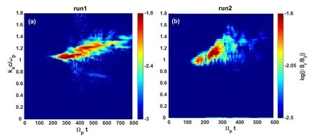
Figure 7.(a) Evolution of the parallel wavenumber kx for run 1, (b) evolution of the parallel wavenumber kx for run 2.Both figures are derived via FFT.

Figure 8.(a) The power ofδBz in the ω−kx plane for run 1,(b) the power ofδBz in the ω−kx plane for run 2.Both figures are obtained via FFT.
Waves become linearly polarized when the perpendicular temperature of protons rises dramatically.This indicates that proton heating is related to the interaction between protons and left/right-handed waves.In the following section,we will study this interaction using the resonant factor.The resonant factor∣ζ±∣, defined asζ±=(ω−k x Uj±nΩp)/k x vjth∣∣,can quantify the resonant interaction between waves and protons.The wave frequency involved,ω,the parallel wavenumberkx,the drift velocityUj,and the parallel thermal velocityvjth∣∣can be determined via following process.
Firstly,we obtainkxat a specific time via the evolution ofkx(shown in figure 7),and then find the correspondingωvia thekx−ωrelation (shown in figure 8); the drift velocityUjcan be obtained from figures 1(c)–(d), the parallel thermal velocity is calculated via the parallel temperature shown in figures 1(a) and (b), andwherevth0is the initial thermal velocity andvth0=0.1vA.These parameters at the moment of Ωpt=300for run 1(Ωpt=250 for run 2) are presented in table 1.Using these parameters,we can quantify the cyclotron resonant factor∣ζ±∣for the beam and core protons in runs 1 and 2,respectively.It should be noted that the values of the Landau resonance factorand the second-order resonance factor
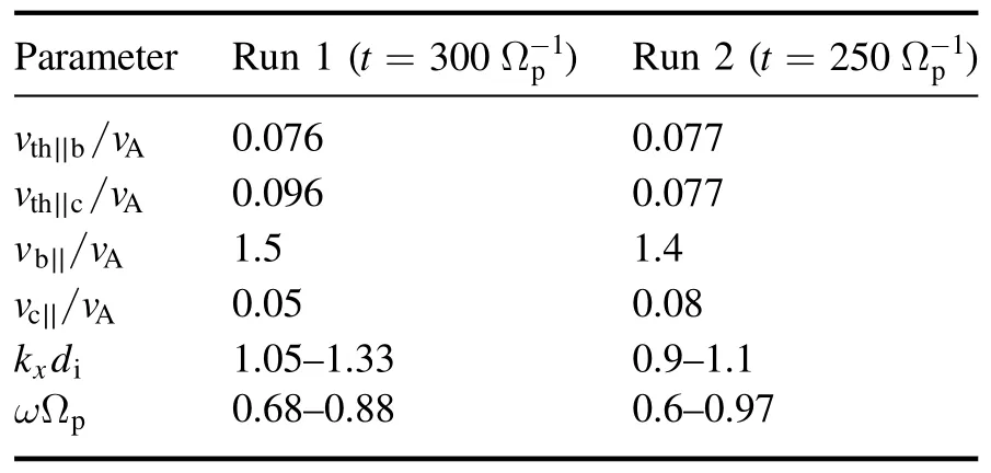
Table 1.Different parameters for run 1 at t =300 Ω−p1 and run 2 att=250 Ω−p1a.
vthc∣∣andvthc⊥are the parallel and perpendicular thermal velocities of the core protons, respectively;vthb∣∣andvthb⊥are the parallel and perpendicular thermal velocities of the beam protons, respectively.vb∣∣andvc∣∣are the drift velocities of the beam and core protons, respectively.are greater than three;this indicates that these two resonances do not contribute to proton heating.Therefore, in this paper, the resonance factor∣ζ±∣jdefaults to the first-order cyclotron resonance factor.

Table 2.Values of the cyclotron resonant factor for beam and core protons for run 1 at t =300 Ω−p1 and run 2 at t =250 Ω−p1.
Substituting these parameters intok x vjth∣∣,we get the ranges of∣ζ±∣ for run 1 and run 2.As shown in the second row of table 2, the cyclotron resonance factor∣ξ+∣is much smaller than∣ξ−∣ for beam protons, indicating that the wave-mode cyclotron resonance with beam protons has righthanded polarization.For core protons,as can be seen in the third row of table 2,∣ξ+∣is much larger than∣ξ−∣, meaning that the wave-mode cyclotron resonance with core protons has left-handed polarization.In addition,the value of∣ξ+∣ for beam protons is smaller than that of∣ξ−∣ for core protons, indicating that the cyclotron resonance between beam protons and right-handed waves is greater in run 1.Therefore,the perpendicular heating of beam protons is more pronounced than that of core protons,which agrees with what was presented in figure 1(a).The situation is different in the case of a larger beam relative density(run 2).As illustrated by the fourth and fifth rows of table 2,the value of∣ξ−∣ for core protons is smaller than that of∣ξ+∣ for beam protons.This implies that the cyclotron resonance between core protons and left-handed waves is stronger.As a result, the perpendicular heating of core protons is greater than that of beam protons,which is consistent with what is shown in figure 1(b).In conclusion, beam (core) protons cyclotron resonate with righthanded (left-handed) polarized waves.The resonance between beam protons and right-hand polarized waves is greater, as the relative density of the beam is less, hence the perpendicular heating of beam protons is stronger.In a larger beam relative density,the reverse condition occurs:the resonance between core protons and left-handed polarized waves is greater, resulting in greater perpendicular heating of core protons.
4.Summary and conclusions
In this paper, using a 2D hybrid simulation model, we investigated the temperature evolution of core and beam protons heated by left/right-handed Alfvén waves generated by electromagnetic proton–proton instability.We demonstrated that initial right-handed elliptically polarized waves gradually become linearly polarized, and eventually take on right-handed circular polarization.Considering that linearly polarized waves are a superposition of left-handed and righthanded polarized waves,the perpendicular heating of protons is caused by cyclotron resonance with left/right-handed waves.Using cyclotron resonant factor, we have proved that left-handed(right-handed polarized)waves resonate with core(beam) protons.When the beam relative density is low, the cyclotron resonance between beam protons and right-handed polarized waves is stronger, resulting in more significant perpendicular heating of beam protons; however, when the beam relative density is large, the condition is reversed.In addition, we found that the wavenumbers and frequencies of the excited waves grew during the evolution.
The change of polarization of the excited waves during the evolution is an interesting phenomenon;it may be closely related to changes in temperature anisotropy or proton drift velocities,and merits further investigation in a future work.In addition, the complicated evolution of the parallel temperature of beam and core protons is an intriguing phenomenon that deserves further investigation in our future research.
Acknowledgments
This work is supported by National Natural Science Foundation of China (Nos.11822401, 41674177 and 41874208).
Data statement
The simulation data will be preserved on a long-term storage system and will be made available upon request to the corresponding author.
ORCID iDs
 Plasma Science and Technology2021年12期
- Plasma Science and Technology的其它文章
- A study on nuclear analysis of the divertor region of the CFETR
- Evaluation of gases’ molecular abundance ratio by fiber-optic laser-induced breakdown spectroscopy with a metal-assisted method
- Thermophysical properties of pure gases and mixtures at temperatures of 300–30 000K and atmospheric pressure:thermodynamic properties and solution of equilibrium compositions
- Plasma treatment for enhancement of the sorption capacity of carbon fabric
- Parametric study of high-frequency characteristics of plasma synthetic jet actuator
- Energy properties and spatial plume profile of ionic liquid ion sources based on an array of porous metal strips
