
Stabilizing subgradesof transport structures by injecting solidifying solutionsin cold regions
2021-12-29 03:14LomovLanisRazuvaevKavardakov
P.O.Lomov,A.L.Lanis,D.A.Razuvaev,M.G.Kavardakov
Siberian Transport University,DusiKoval'chuk St.,191,Novosibirsk,630049,Russia
ABSTRACT Transport structures built throughout the period from 1960 to 1980 in permafrost regions based on the principle of perma‐frost preservation are subject to deformations.In many cases,the reason is a gradual change in temperature and their sub‐grade condition within the active zone due to the structures'technogenic impact.Design solutions for the fifty-year-old structures fail to ensure in all cases their reliable operation at the present time.The greatest danger to the reliable operation of railway lines in cold regions is uneven deformations of bridges,which are barrier places.Therefore,the solution to this problem is urgent especially due to the necessity of increase carrying capacity.The purpose of this study is to increase reli‐ability of bridge operation in cold regions through strengthening the subgrade by reinforcement with injection of solidify‐ing solutions.The problem of uneven deformations due to permafrost degradation is considered using the example of a railway bridge located in the northern line of the Krasnoyarsk railway.Deformations of the bridge abutments began imme‐diately after the construction was completed and the bridge was open for traffic-since 1977.Permafrost degradation was developing more actively straight under the abutments due to higher thermal conductivity of the piles concrete.Notably,thawing intensity of frozen soils under the bridge abutments is uneven due to its orientation to the cardinal points.The analysis of archive materials and results of the geodetic survey made it possible to systematize the features of augmenting deformations of each abutment over time.The engineering-geological survey with drilling wells near the abutments en‐sured determination of soil characteristics,both in the frozen and thawed states.Thermometric wells were arranged to measure temperatures.The analysis and systematization of the data obtained allowed us to develop geotechnical models for each abutment of the bridge.The peculiarity of these models is allowance for changes in the strength and deformation characteristics of the soil calculated layers depending on changes in temperature and the soil condition.Thus,different cal‐culated geological elements with the corresponding strength and deformation characteristics were identified in the soil lay‐ers of the same origin.The analysis of the systematized geodetic data allowed us to confirm adequacy of the developed geotechnical models.Studies carried out using geotechnical models made it possible to predict improvement of physical and mechanical characteristics of the subgrade to prevent further growth deformations of the bridge abutments.The meth‐od of reinforcement by injection is proposed.Injecting a solution under pressure leads to strengthening of weakened thawed soils and improving their physical and mechanical properties.This research theoretically substantiates and devel‐ops the geotechnical models of the reinforced pier footing of bridge abutments by injection of solidifying solutions.The models take into account the reinforcement parameters and elements for the case in question.The influence of reinforce‐ment on the change in physical and mechanical properties of the soil mass is determined.
Keywords:reinforcement of soils;injection of solidifying solution;strengthening of pier footing soils;geotechnical model;bridge abutments;deformations;plastic frozen soil;permafrost degradation
1 Introduction
Transport facilities,built during 1960−1980 in permafrost rock areas according to the permafrost conservation principle,tend to experience deforma‐tions.In many cases,the underlying cause is gradual changes in the temperature and state of their subsoil within the active zone due to the technogenic effect of structures(Isakov,2015;Shastunova and Mi‐chailov,2017)and global climate change(Shroder et al.,2015).In this context,facility designs implement‐ed up to 50 years ago fail to always ensure their reli‐able operation at present.This problem is quite com‐mon in permafrost areas(Tomilov et al.,2020).Un‐even deformation of bridges,as barrier places,repre‐sent a considerable danger in terms of reliable opera‐tion of railway lines in cold regions.Therefore,find‐ing a solution to this problem is imperative,especially in view of the need to increase their carrying capacity.
One of the ways to stabilize subgrades of trans‐port works is to inject solidifying solutions which re‐sults in the formation of a supporting geotechnogenic structure that includes the solidified solution,com‐pacted soil and undisturbed soil(Lanis,2016).
Berigny(1802),in France,was the first to inject solidifying solutions under pressure into soils(Cambe‐fort,1971;Adamovich,1980).Theoretical substantia‐tion of injection varieties by solidifying solutions with numerous examples is given in the monograph by Cambefort(1971).The method under consider‐ation has been widely used in various areas of trans‐port construction,such as strengthening buildings'and structures'footings,strengthening subgrade soils and body,and soil surrounding tunnels(Khamov,1997;Nicolini and Nova,2000;Lanis,2016).The issues of using injection of solidifying solutions to increase the operational reliability of transport structures saw the first in-depth study in the thesis of Lanis(2019).
2 Object of study
Using the case of the deforming single-span rail‐way bridge on the northern line of the Krasnoyarsk railway,the authors carried out a study aimed at devel‐oping new solutions to eliminate the problem of struc‐ture deformations(subsidence)caused by degrading subgrade permafrost.
For this study,the single-track single-span strength‐ened-concrete bridge,12-m length,3-m height of an approach fill,erected in 1977,was chosen,the bridge supports being massive(Figure 1).The bridge is designed according to the permafrost conservation principle.Permafrost soils of the subgrade fall into the active zone of the bridge abutments.
Deformation of the bridge abutments began in 1977 immediately after construction completion and opening for traffic.In the late 1990s,a range of restora‐tion works were carried out to eliminate the conse‐quence of deformations.At the beginning of the 2000s,however,deformationsof the abutments began again.
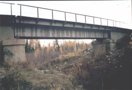
Figure 1 General view of the bridge
In the course of studying the archival data on the bridge,it was found that the deformations are associ‐ated with degradations in the frozen subgrade soils.The gradual thawing of the subgrade with a decrease in the roof of permafrost soils is a consequence of vio‐lating the thermodynamic balance during initial con‐struction and structure operation.The process of per‐mafrost degradation was more active immediately un‐der the abutments.
A reason of permafrost degradation in such cases is the change in the seasonal duration of the cold and warm periods due to global warming(Konishchev,2009).
3 Engineering and geological conditions
An engineering-geological survey was carried out on the bridge in question with drilling of control wells near the deforming abutments.As a result,data was obtained on changes in the engineering-geological conditions of the site during its long-term operation,enabling to predict development of further subgrade de‐formations.The range and scope of the work on the en‐gineering and geological survey were determined tak‐ing into account the geological and climatic features of the bridge location(Lanisand Razuvaev,2017).
The survey testified that the approach fill is com‐posed of gravelly loam of hard consistency.The upper part of the section is represented by gravel soil with sandy loam filler.The middle part is very soft light gravelly loam and very soft heavy gravelly loam.In the lower part of the section,there are hard frozen heavy gravelly loams and gravelly clays.The longitudi‐nal engineering-geological profile along the soils of the bridge subgrade as of 2020 is presented in Figure 2.
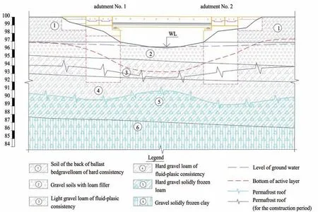
Figure 2 Longitudinal engineering-geological profile of soils of the bridge subgrade in 2020
Archival data prove that while designing and con‐structing the bridge,massive foundations of abut‐ments rested upon hard-frozen heavy gravelly loams located at depths of 4.9 to 5.1 m.The multiyear opera‐tion of the bridge saw the thawing of the permafrost subgrade with the change of the roof boundaries of the permafrost soil under the abutments as well as the formation of weak soil interlayers-very soft gravelly loams-at the bridge subgrade(elements 3 and 4,Figure 2).
To clarify the location of the permafrost roof,ther‐mometric wells were laid near the deforming abut‐ments with the survey by periodic monitoring the dy‐namics of changes in the temperature regime of the bridge subgrade.Figure 3 shows the graph of the sub‐grade soils temperature of abutment No.1.
Analyzing the archival data on the object of the study and the data on temperature measurements,it was found that the depth of the location of the frozen soil roof has changed since the construction of the bridge.At present,the bench of the permafrost roof is located at a depth of 6.9 to 7.1 m from the level of the day surface.
The gradual thawing of the soil at the bridge sub‐grade led to additional vertical deformations,which generally correlates with the materials of the geodetic survey.
The data obtained allow us to conclude that the degradation of permafrost has stopped.
Despite the formed permafrost boundary,deforma‐tions of the bridge continue through the present due to long-term consolidation of very soft gravelly loams at the base of the abutments(elements 3 and 4,Figure 2).Besides,in the event of an increase in carrying ca‐pacity,the loads transferred to the thawed subgrade will inevitably increase,which will also contribute to additional subsidence.
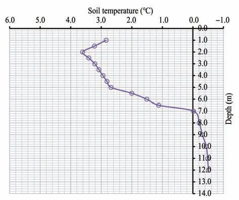
Figure 3 Graphs for measuring soil temperature by depth(the temperature was measured in October)
4 Theoretical research
An option for solving the problem of additional subsidence of the base of bridge abutments in the course of consolidation of thawed soils and a pro‐spective increase in loads on the roadbed is strength‐ening of soft soil layers by injecting a solidifying solution.
After introduction of any solidifying compounds into strengthen soils,the temperature balance will be disturbed due to their own heat as well as possible exothermic processes.This can lead to additional deg‐radation of the permafrost and additional subsidence of the thawed soil.As a result,several repeated injec‐tions of solidifying solutions may be required,accom‐panied by thawing of the frozen soil.Thus,quantify‐ing the effects of injection and estimating the number of re-fixings becomes essential.
In order to understand the consequences of inject‐ing solidifying solutions into thawed soils that are in contact with frozen soils and to assess the possibility of using the strengthening of soil in the permafrost conditions,the authors have solved the following problems:
(1)the amount of heat generated by the strength‐ened mass after injecting the solidifying compounds is estimated;
(2)the dimensions of the soil thaw layer after in‐jecting solidifying compounds are determined;
(3)a geotechnical model is developed enabling to assess the additional subsidence of the bridge from thawing of frozen soil due to injecting the solidifying compounds;
(4)a method is devised to strengthen the thawing subgrade by injecting solidifying solutions under the permafrost conditions.
4.1 Thermotechnical model
Introduction of solidifying solutions into thawed soils in contact with frozen soil will inevitably change the temperature regime of the bridge subgrade due to changed heat exchange conditions at the boundaries and within the soil mass being strengthened.Predict‐ing changes in the temperature regime of the calculated region will allow determining the temperature fields in the soil mass and identifying the thawing zones.
The change in the temperature regime of the calcu‐lated region is limited by the heat exchange condi‐tions and the change in temperature or heat fluxes over time.In addition,for accurate forecasting,it is impor‐tant to haveinitial data(conditions),which include:
-initial temperature distribution in the calculated region;
-phase state of the material(thawed or frozen state of the soil)at the baseline;
-basic thermophysical properties of materials:heat capacity and the thermal conductivity factor;
-content of latent heats when the phase state is changing at the moment the material reaches a certain temperature.
Accurate measurement of changes in the tempera‐ture regime of soil mass is possible by applying the el‐ementary balances method,which is a variation of the finite elements method.The calculation is effectively reduced to mathematical modeling of heat transfer in time,which in its duration is proportionate to the dura‐tion of an actual physical process.
Heat conductivity of a particular material is to be taken into account which depends on its temperature and the content of latent heats.It changes abruptly at 0℃(or other temperature set in the source data)when the content of latent heats in the calculated re‐gion increases(thawing)or decreases(frost)relative‐ly to the control value.Latent heats are generated(ab‐sorbed)at 0°С.Soil thermal capacity is taken up con‐stant rate accordingly for the thawed or frost state.Thus,when calculating the heat generated in the cal‐culated region after solidifying solutions have been in‐troduced,the heat losses from preheating the sur‐rounding soil before the phase transfer(thawing)should also be taken into account.
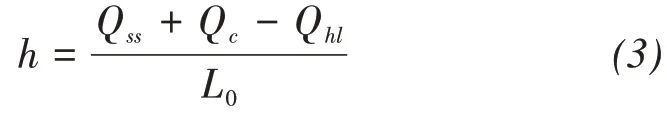
Regarding the problem in question,heat transfer takes place from the strengthened thawed soil to the underlying frost soil of the subgrade.For the strength‐ened thawed soil,the amount of heat involved in heat transfer can be defined as:
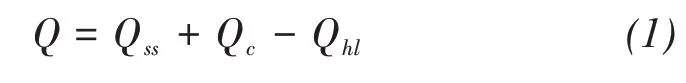
where Qssis the amount of heat introduced to the soil mass with a solidifying solution(solution own heat),kJ;Qcis the amount of heat generated in the strength‐ened soil mass due to the cement exotherm(heat gen‐eration),kJ;Qhlis heat losses in the strengthened soil mass caused by heating the surrounding frost soil be‐fore the phase transfer,kJ.
The amount of latent heat required for the phase transfer of frozen water in 1 m3of soil can be defined(Concrete and Reinforced Concrete Research Insti‐tute,USSRState Construction Committee,1982):

where L is the heat amount of"water-ice"phase trans‐fers,kJ;ρdis dry unit weight of soil,kg/m3;Wtotis soil moisture,%;Wwis water content in frost soil with the account of unfrozen water,%.
In some cases,mathematical modeling of heat transfer should be done by means of modern software packages to ensure high accuracy of the calculations.In the task at hand on estimating the size of a thawing interlayer,however,a simplified model can be used,that does not require defining the temperature fields and the set-up time of the temperature balance in the calculated region.
The authors have developed a simplified method to determine the size of a thawing interlayer when strengthening thawed soils by injecting a solidifying solution,based on the existing method for calculating a thawing interlayer when concreting strip founda‐tions(Concrete and Reinforced Concrete Research In‐stitute,USSR State Construction Committee,1982).This simplified method involves calculating the com‐ponents of the heat amount and heat losses for the strengthened soil mass according to known thermody‐namic laws without defining temperature fields in the calculated region.
This simplified model contains the calculated re‐gion of the strengthened soil,in which components of the generated heat are calculated,bounded by the foundation of the bridge structure above,by the fro‐zen soil below,as well as by the thawed soil on the sides.The simplified model was developed on the as‐sumption that heat losses occur due to heating of fro‐zen soil,and all the remaining heat is spent on the phase transfer of frozen water in the ground.
Thickness of the thawing interlayer can be deter‐mined from the ratio of the heat in the strengthened soil mass to the heat of the phase transfer:
The amount of heatQssintroduced into the soil mass by the solidifying solution(own heat of the solu‐tion)can be determined as:

whereε1is the share of the solidifying solution in the strengthened soil mass;WCis the water-cement ratio of the solidifying solution;Cwis the specific heat of water,kJ/(kg·°С);tpis the temperature of the injected solidifying solution,°С;tbfis the soil freezing temper‐ature,°С;ρpis the density of the solidifying solution,kg/m³;Sis the contact area of the frozen soil with the strengthened soil mass,m;zis half the capacity of the strengthened soil mass(Concrete and Reinforced Con‐crete Research Institute,USSR State Construction Committee,1982),m.
The amount of heatQcreleased in the strength‐ened soil mass due to the cement exotherm can be defined as
whereqcis the heat generation of 1 kg of cement,kJ/kg;Mcis the cement consumption per 1 m³of the solidifying solution,kg.
Heat lossesQhlin the strengthened soil mass due to the surrounding frozen soil heating before the phase transfer can be defined as

whereε2is the coefficient that accounts for the interac‐tion of frozen soil with the strengthened soil mass(Concrete and Reinforced Concrete Research Insti‐tute,USSR State Construction Committee,1982);Cfis the specific heat capacity of frozen soil,kJ/(kg·°С);ρfis the frozen soil density,kg/m³;tfis the frozen soil temperature,°C.
4.2 Geotechnical model
Estimating the size of the soil thawing zone ac‐cording to the Equation(3)from the effect of the so‐lidifying solution enables forming a geotechnical model of the bridge subgrade.Thus,it is possible to predict additional deformations of the structure while the thawed soils are strengthened.
Complete stabilization of the subgrade deforma‐tions can be achieved through several injection stages.
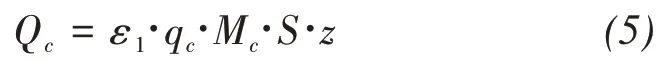
In order to assess the additional subsidence from the thawing of frozen soil after injections of the solidi‐fying solution,the authors have developed the geo‐technical model(Figure 4).Description of the geo‐technical model elements are depicted in Table 1.
4.3 Design algorithm
The proposed simplified method for defining di‐mensions of the thawed layer and the geotechnical model of the structure for calculating additional sub‐sidence have allowed the authors to develop the de‐sign algorithm for strengthening the thawed subgrade by injecting the solidifying solution in cold regions(Figure 5).
The methods and approaches used impose a num‐ber of boundary conditions for the applicability of the developed design algorithm aimed to stabilize the transport structures subgrade in cold regions with in‐jecting solidifying solutions.
1.Thermotechnical forecast should indicate the completion of degradation of the subgrade permafrost in depth;
2.The degradation rate of subgrade permafrost soils during structure operation should exceed the thawed subgrade consolidation rate,as a result of which clay soils layers with insufficient bearing ca‐pacity are formed in the subgrade.
3.Depth of the solidifying solution injecting must be at least 1 meter from the level of the day surface.
4.4 Calculation
For the railway bridge under analysis,the pro‐posed design algorithm for strengthening the thawing subgrade is applied.
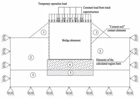
Figure 4 Geotechnical model for calculating the additional subsidence value

Table 1 Description of the elements of the geotechnical model
Using the simplified method for determining di‐mensions of the thawed interlayer when strengthening thawed soils by injecting solidifying solutions and the geotechnical model,the forecast is made of additional deformations of the structure from strengthening the thawed soils and the number of strengthening stages is determined to stabilize deformations of the bridge subgrade.
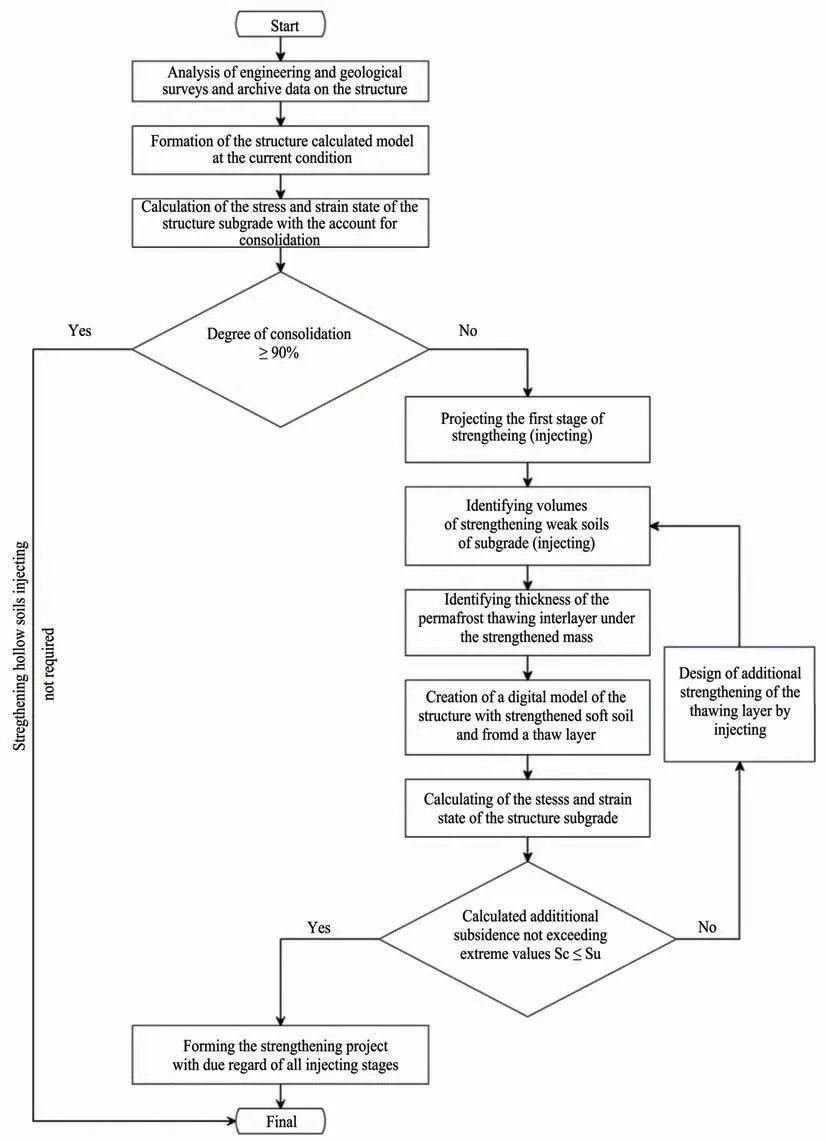
Figure 5 Design algorithm for strengthening the thawed subgrade by injecting solidifying solutions in cold regions
Using the existing design and modeling tech‐niques(Lanis,2018a;Lanis,2018b),previously devel‐oped by the authors of the present paper,it is possible to determine the optimal consumption and recipe of solidifying solutions to strengthen thawed soils and stop bridge deformations,as well as to take into ac‐count the strengthened mass in the model.
Table 2 presents the main thermophysical and me‐chanical characteristics of soils and materials used in the geotechnical model formation.
The digital model of the structure,built up accord‐ing to the developed geotechnical model,taking into account the engineering and geological conditions of the bridge subgrade,is presented in Figure 6.Numerical modeling was performed in the MIDAS GTSNX software package.

Table 2 Main thermophysical and mechanical characteristics of soils and materials
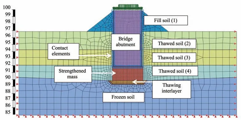
Figure 6 Structure's digital model
The digital model takes into account the rein‐forced soil mass that is located in the thickness of the thawed soil(element 4)between the foundation of the bridge abutment and the frozen soil(element 5).Strengthening is assumed to be carried out by inject‐ing the soil-cement solidifying solution into the soil layer along the entire width of the model foundation(4 m)to a depth of 2 m.The impact of the 15°C solu‐tion heat in combination with the heat release from the cement exotherm will lead to the formation of a 43-cm-thick lens-shaped thawing zone located under the strengthened mass.
The deformed view of the structure model when modeling the thawing of frozen soil after the first stage of strengthening is given in Figure 7.
As can be seen(Figure 7),a weak soil layer formed by the heat release of the solidifying solution under the strengthened mass triggers the development of additional,mainly vertical,deformations of the model.Numerical modeling allowed us to determine the additional bridge subsidence equal to 9.6 mm.
The resulting vertical deformations exceed the ac‐cepted values for this type of structures.Therefore,the second stage of strengthening is formed in the model.
Repeated strengthening of the bridge subgrade is also accompanied by the injection of solidifying ce‐ment-based grout into the weak soil layer.At the sec‐ond stage,however,dimensions of the strengthened mass are smaller and correspond to the dimensions of the interlayer thawed from the first stage of strength‐ening(a 43-cm-thick lens across the width of the foundation base).In this case,deformation of the model occurs according to the scenario similar to the one in the first stage,yet,in the given case,values of deformations are significantly lower.Excess heat re‐lease(from the solution's intrinsic heat and the ce‐ment exotherm)will form a new thawing lens 7 cm thick,the compression of which will cause an addi‐tional 1.9 mm subsidence of the bridge.
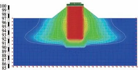
Figure 7 Deformed view of the structure model
The obtained results of numerical modeling,in particular,the size and location of the thawed soil areas from the heat release effect of the injected ce‐ment-based solution and the nature of the model's de‐formation while such areas are being formed,qualita‐tively coincide with the results of studies by S.A.Kudryavtsev,I.I.Sakharov and V.N.Paramonov of the issues of numerical implementation of thermo‐physical problems and stress-strain state problems during freezing and thawing(Kudryavtsev et al.,2014).Thus,it is found that for the bridge under con‐sideration,it is sufficient to perform two stages of soil strengthening by injection of solidifying solu‐tions to stabilize the subgrade.
5 Conclusions
1.A simplified method is developed to assess the thickness of frozen soil thawing influenced by inject‐ed solidifying cement-based solutions alongside with strengthening soft soil layers in permafrost,taking in‐to account heat exchange at the boundaries and within the strengthened soil mass.
2.A geotechnical model of the bridge subgrade is proposed,enabling to assess changes in the stress-strain state of the subgrade soils from permafrost degrada‐tion and to predict additional structure deformations when thawed soils at the border with frozen soils are strengthened.
3.A design algorithm is proposed for projecting the strengthening of the thawing subgrade by inject‐ing solidifying solutions in cold regions.
4.For the existing railway bridge that experiences ongoing deformations from permafrost degradation,the stage-by-stage strengthening of the thawed soils by injecting solidifying solutions is proposed.
5.The obtained results of modeling the strengthen‐ing of thawed soils by injection of solidifying solu‐tions in the existing railway bridge subgrade are quali‐tatively comparable with the relevant results of inde‐pendent studies obtained by other authors.
 Sciences in Cold and Arid Regions2021年5期
- Sciences in Cold and Arid Regions的其它文章
- Review and prospect of the effectsof freeze-thaw on soil geotechnical properties
- Rationale for creation of capillary breaking layersin cold regions subgrade by pressure injection of waterproofing compounds
- Lessonsfrom construction and health condition evaluation of high-grade highway in permafrost regions
- Study on tensile damage characteristicsof sandstone under freeze-thaw cycles
- Numerical simulation of electroosmosis in unsaturated compacted clay
- Field monitoring of differential frost heave in widened highway subgrade