
Single Wavelength Near-Eye Display Glasses
2021-11-30 09:50,,,
西安工业大学学报 2021年5期
关键词:系统
, , ,
(School of Optoelectronic Engineering,Xi’an Technological University,Xi’an 710021,China)
Abstract: In order to make the monochrome augmented reality optical system smaller in size,easier to wear,and have a larger field of view and clearer and brighter imaging,the design of an optical system and the evaluation of its display effect are completed based on the principles of double grating and planar waveguide.The models of eyepiece optical system,coupling optical system,planar waveguide system and coupling out system are optimized and built based on Zimax software.Taking the real image transmission as the goal,the simulation results are verified experimentally.Experiment shows that when the single wavelength is 532 nm and the yield distance is 8 mm,the system structure is correct and reasonable,which can realize a 20° field of view and 10 mm large exit pupil display,with the image similarity being 34.8.
Key words: near-eye display;optical design;diffraction grating;diffractive optical waveguide
0 Introduction
Augmented Reality (A-R) display plays a vital role in the military industry,industrial manufacturing,medical equipment and daily life.According to relevant experts’ evaluation,AR glasses will replace the most popular mobile phones and become the next generation of new collaborative computing[1].the near eye perspective display is the main component of AR equipment.It can overlay virtual images into the surrounding landscape,enabling observers to receive information from AR devices while still immersing themselves in the real world.
The existing methods for near eye perspective display include free form optical prism,projection system,holographic grating etc[2].The optical waveguide display is light and compact,and has the advantages of structure,which significantly improves the portability and mobility of the device.In order to realize full color grating imaging,a new challenge is proposed.Waveguide technology is widely considered to be one of the most promising methods to realize the combination of augmented reality (AR)/hybrid reality devices with the minimum overall size.However,these still face a number of technical challenges,such as higher optical efficiency,wider field of view,lighter and smaller size.Compared with the traditional optical system,waveguide technology can reduce the size and weight of the system to the greatest extent and the energy loss.The traditional optical system is difficult to design,and will produce a variety of aberrations,and its volume and weight cannot meet the requirement[3-5].The size and weight of the AR display system can be greatly reduced by using diffractive optical waveguide instead of traditional optical elements.Moreover,the total reflection of light beam in the optical waveguide can realize the expansion of pupil,which makes the observation range of binocular field of view wider and improves the imaging quality.Diffraction grating is almost pure refractive index modulation,which can greatly improve the coupling efficiency of the system[6-8].
According to the relative theory,if the grating period is the same,the dispersion problem of monochromatic light can be eliminated.The idea of using a diffractive waveguide was first patented in 1987,but it did not receive much attention at that time[9].In 2001,it was patented as a near eye display application.With the continuous improvement of optical design and precision manufacturing methods,diffractive waveguides have been successfully used in military operations[10].
Due to the immature development of domestic display technology and the foreign monopoly of related technology,only a part of it can be verified by experiments[11-13].In order to meet the requirements of AR display miniaturization and lightweight development,a new design scheme based on diffractive optical waveguide is proposed.The main contents are as follows:firstly,the principle of AR optical system is introduced.Secondly,the related technology and principle of diffractive optical waveguide display are analyzed.Finally,the display system of diffractive optical waveguide with green light source is designed,simulated and experimentally verified.
1 Analysis of design requirement
According to the requirements of the project specification,the optical system is calculated and designed and then simulated by ZEMAX.The main contents are as follows:① design of near eye display system:ZEMAX is used to design the optical system of near eye optical display,including the eyepiece optical system,human eye model,coupling optical system,planar waveguide system and coupling exit optical system;② processing and assembly of optical components:completing the processing and assembly of main optical components;③ experiments verification:the technical indicators of the near eye display system are tested.The technical indexes of the project are as follows:
(a)The binocular diagonal field of view is greater than 20°;
(b) The exit pupil diameterDis 8 mm,and the exit pupil distance is 15 mm;
(c) The holographic waveguide thickness is less than 3 mm.
1.1 Analysis of the principle
The diffractive optical waveguide display system to be designed is shown in Fig.1,which is mainly composed of a micro display,an eyepiece system,a waveguide and inlet and outlet diffraction gratings.The in and out diffraction gratings are composed of reflective diffraction gratings.The working principle of the diffraction light waveguide display system is:the image source on the computer display screen is projected in a micro display,and then the beam is expanded and collimated by the eyepiece system,and the parallel light is irradiated on the diffraction grating at the coupling end through the waveguide[14-16].Due to the diffraction effect of the diffraction grating,the propagation direction of the parallel light is changed,and the light in the waveguide is limited under the condition of meeting the total reflection condition.It propagates forward in the waveguide direction.When the parallel light propagates to the diffraction grating at the coupling end,the total reflection condition is destroyed,and the light is diffracted again,and the parallel light comes out of the waveguide,entering the human eye for imaging.
The optical structure of the AR system is simple,and the optical element of the intermediate image transmission is just a simple eyepiece system,which can magnify and collimate the light.It does not need a very complex lens group and relay image transmission system.It greatly reduces the size and weight of the system,realizing miniaturization and portability,which meet the requirements of mass production and market application.Because the out coupling diffraction grating and the in coupling diffraction grating replace the traditional lens group,not only the transmission distance of the image and the aberration of the system are reduced,but also the pupil dilation in the horizontal and vertical directions is implemented,and the size and weight of the system are reduced,which is conducive to the simple design of the whole system.
1.2 Image source
One of the core components of the AR display is the image source.The definition and color composition of the image source directly determine the performance of the display.In order to ensure that the image source has enough definition,no stray light and high recognition,high-resolution micro display is mostly adopted.This display is light and small,which can reduce the overall weight and size of the system,and ensure that the clarity of the image source has no impact on the imaging of the system.There are many kinds of AR displays due to the different choices of display as the image source.At present,LED,LCD and LCOS are the main image sources of HMD[17].After considering comprehensive experiment,and the display parameters,the micro-LCD was selected and basic parameters are shown in Tab.1.
1.3 Optic system
The optical system is composed of an eyepiece collimation system,an optical waveguide and a diffraction grating.The collimated light projects into the coupling grating,and propagates in the optical waveguide and then is fully reflected out of the coupling grating,and finally enters into the human eye for imaging.The optical system is shown in Fig.2.
1.3.1Opticalcharacteristicsoftheeyepiece
The eyepiece of the visual optical system is the instrument by which the human eye can receive the image source.The observed object is usually located at the object plane of the eyepiece,and the outgoing light is parallel light.After being magnified and collimated by the eyepiece system,it is imaged at infinity.During observation,the eye should coincide with the exit pupil of the eyepiece,and the position of the pupil is generally 8 mm.Therefore,the magnification of the eyepiece is 250/(f2′ ),wheref2′ is the focal length of the eyepiece.The Kenier system is shown in Fig.3.

Fig.3 Kenier system
Basic characteristic parameters of the eyepiece are as follows.According to the requirements of the AR system,the calculation parameters are as follows:exit pupil distancep=15 mm,eyepiece tube length=10 mm,eyepiece focal lengthf2′=16 mm.PMMA and zf3 materials are to be used for gluing,L_1and the lens are also made of PMMA material,n=1.5.Through calculation,f1′=24.3 mm andR1=17 mm can be obtained.The specific calculation is carried out in the eyepiece system and human eye image calculation part,and the preliminary simulation is carried out in ZEMAX to determine whether the system meets the overall system requirements.
1.3.2Reversaldesignoftheeyepiecesystem
According to the actual functional requirements of AR glasses,it is necessary to reverse the design of the eyepiece system,that is,reverse the designed system.The optical path designed by ZEMAX simulation is shown in Fig.4.

Fig.4 Kenier system simulation
1.4 Design of the diffractive optical waveguide
1.4.1Principleofthediffractiveopticalwaveguide
The schematic diagram of the diffraction waveguide is shown in Fig.5.
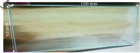
Fig.5 Diffractive waveguide
The image source is output through beam expansion and collimation of the kenel eyepiece device and then is coupled into the waveguide by gratimg,and next propagates in the waveguide under the condition of total reflection.The light is modulated by the coupling diffraction grating after multiple total reflection in the waveguide,and the image is coupled out of the waveguide to enter into the human eye for imaging[18].
1.4.2Designofdiffractiveopticalwaveguide
The length of diffraction grating is determined according to the size of the eyepiece exit pupil.In ZEMAX,the diffraction grating is simulated under the condition of non-sequential parallel light.If the setting parameters are satisfied,the light can be totally reflected in the optical waveguide.
The visual field angle we need must be greater than 20°.According to the formula:
d(sinφ+sinθ)=mλ.
(1)
The angle is required to be greater than 41.8°.Based on the calculation formula for full reflection:
sinθc=n2/n1.
(2)
The refractive index of our material is calculated to be more than 1.5.So we can choose the glass plate of PMMA material as wave guide.The size of image source is 8.45 mm,which determines that the minimum wave guide thickness is 3 mm.And the length and width of the wave guide are determined to be 100 mm and 50 mm,respectively,by the position of the coupling grating.
1.4.3Analysisofopticalaberration
According to the aberration analysis of the system shown in Fig.4,it is found that the outer axial beam of the optical system does not converge to a point,indicating that there is a difference between the systems.Using THES TOMA,the evaluation function operator number provided by ZEMAX is used to optimize the difference,and the best optical system is found through ZEMAX’s local optimization and global optimization.The system parameters of sequence data and non-sequence after optimization are shown in Tab.2~3 respectively.
The designed system is analyzed,as shown in Fig.6~7.
Fig.6 shows an image simulation after system optimization.It can be seen that the imaging effect have met the basic imaging requirements.Fig.7 shows the system’s point column diagram and distortion.The maximum radius of the square root dispersion spot is 2.198 μm and the maximum distortion becomes 3.73%,meeting the imaging requirements.

Tab.2 Sequence data of system parameters表2 序列模式的系统参数

Tab.3 Non-sequence data of system parameters表3 非序列模式的系统参数

Fig.6 Image simulation
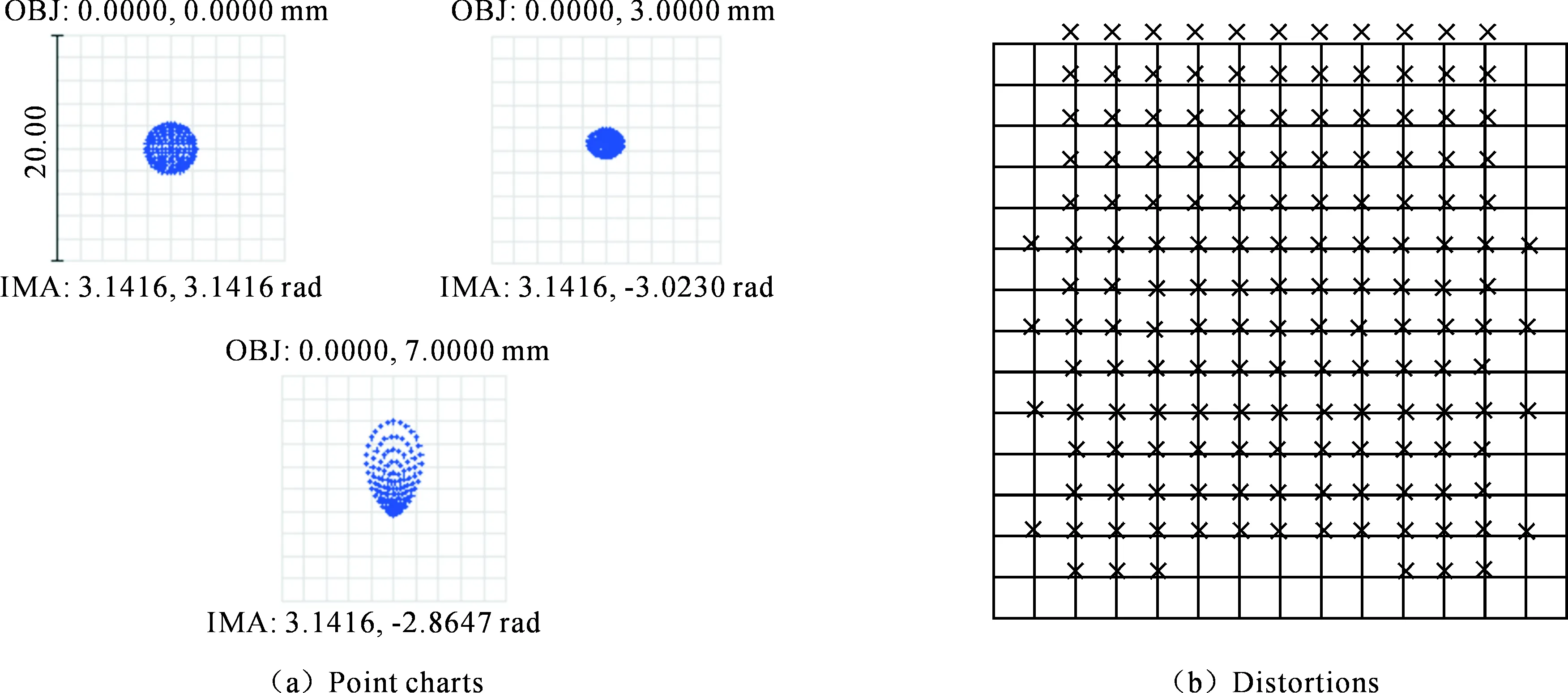
Fig.7 Point charts and distortions
2 Experimental verification
In order to verify whether the correct optical path and image can be obtained through the design,an experiment is carried out in this part.
2.1 Composition of the optical system
The existing system designed is used to verify whether the diffractive waveguide plays a turning role in the optical path.As shown in Fig.8,the main structure is composed of a light source,diffraction grating,planar waveguide and an imaging plate.The light source is 532 nm green laser.The diffraction grating is 20×20 mm in size,3 mm in thickness,250 nm in blaze wavelength and 190~850 nm in working wavelength.It is an optical glass base with dense and equidistant parallel lines,coated with aluminum reflection film,which can couple imaging light into waveguide through diffraction effect.The white board is used to receive the imaging light.Figure 8 shows that vertically incident light can be diffracted out of the coupling grating,and the diffraction angle also meets the total reflection condition,and then the light can transmit in a shape of letter W in the optical waveguide[19].Through Fig.8(b),we can clearly find that the vertical incident light can have total reflection in the waveguide,and the output diffraction grating modulation light at the output coupling end of the waveguide can receive the outgoing light on the imaging plane,which proves the rationality and scientificity of the optical path of the augmented reality optical system designed in this paper.
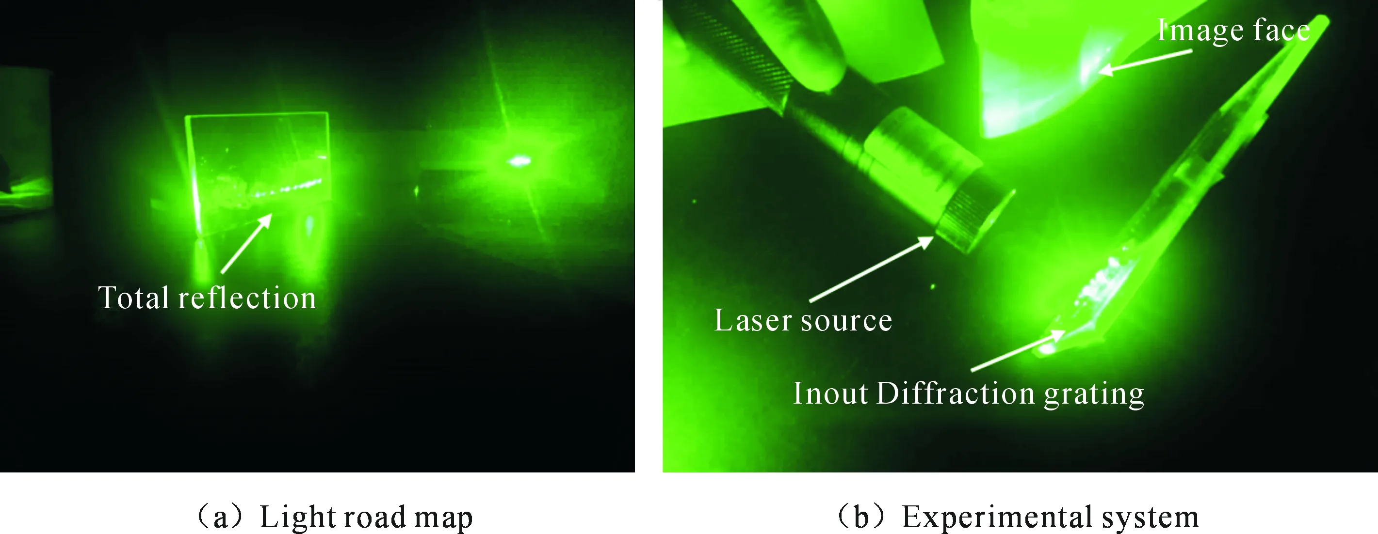
Fig.8 Full-reflection simulation
2.2 Building the imaging system
The experimental system is shown in Fig.9.Firstly,the three primary colors of the logo of Xi’an Technological University are extracted by Matlab,as shown in Fig.10(a),and the image source becomes monochromatic image source,as shown in Fig.10(b).The extracted monochromatic image source is connected with a micro display to output the image source.The output image source can be obtained by collimating the light through a collimating lens where the micro display was placed at the object focus of the lens. Then,adjust the grating into the coupling in to the center of the eyepiece so that the light is totally reflected inside the waveguide,and finally place the phone at the coupling out of the grating for image acceptance[20].
The imaging plane firstly is found out through the human eye observation,and then the mobile phone camera is used to shoot it,as shown in Fig.10(c).It shows that the loss of light energy is large and the coupling efficiency of diffraction grating is low,leading to the degradation of imaging quality.The experimental conditions are relatively simple,and cannot meet the requirements for fine-tuning.And the resolution of the receiver mobile phone cannot meet the requirements of high-resolution.
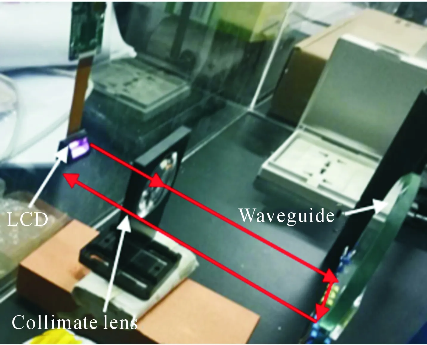
Fig.9 Experimental system
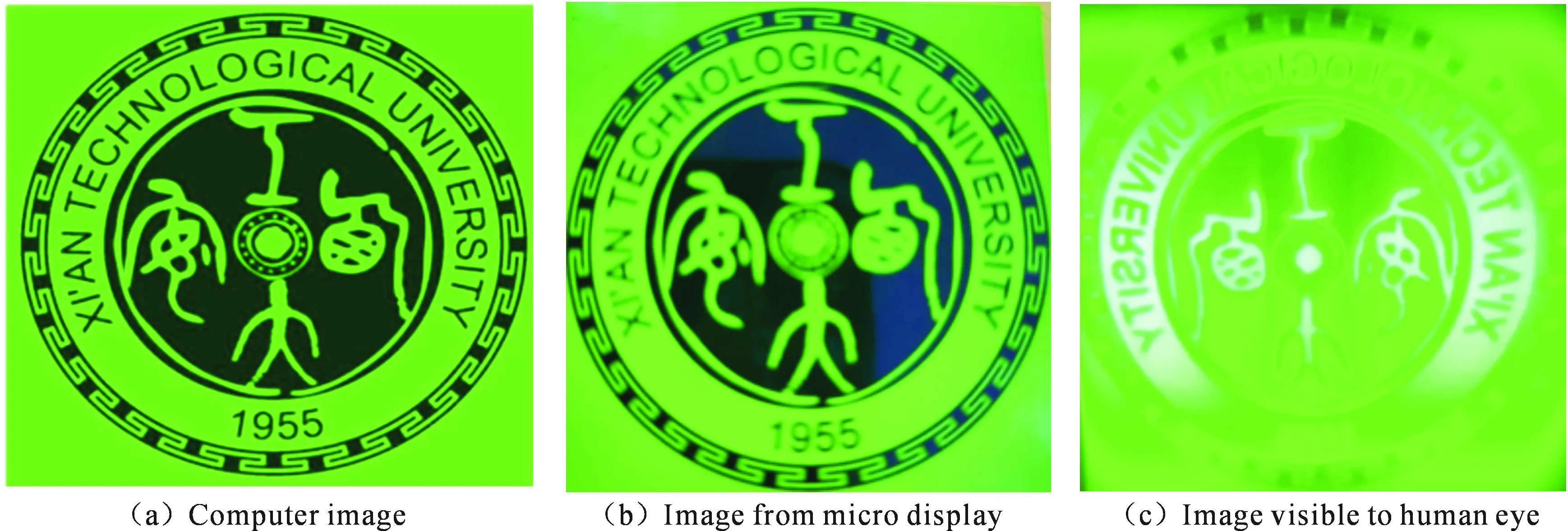
Fig.10 Image simulation
3 Error analysis
Many bubbles and glue particles are found in the glued surface of grating and waveguide with an optical microscope,as shown in Fig.11(a).Our project will change the refractive index of the bonding surface,so that the light cannot be emitted,resulting in the loss of light,and low image quality.The prepared glue is evenly distributed on the grating surface by the glue homogenizer,and then vacuumized by the coating machine.In the process of setting up the experimental device,manual operation is adopted,which may cause irreversible damage to precision optical devices.Dust,temperature,humidity and light in the air will affect negatively the efficiency and imaging quality of grating for light coupling.The aluminum film on the surface of the grating will be scratched during the gluing process of diffraction grating,as shown in Fig.11(b),and the more times of gluing,the greater the damage.The relay system uses a lens to collimate the light,so that the light is perpendicular to the surface of the diffraction grating.Secondly,there are some errors in the process of data acquisition by using a mobile camera.Through MATLAB software using the structural similarity(SSIM)function to process the image similarity,we can find that the similarity of two images is only 37.8%,showing that the image quality is very poor.

Fig.11 Reason for unclear image
The designed optical system is in accordance with the principle and the technical index of optical design.Through the analysis of the optical microscope and various instruments,we can see that there is big room to improve the construction of the system,which has a great impact on the image quality.
4 Conclusion
In this paper, the design and application of AR glasses systems with the diffractive waveguide structure was discussed and the technical route of double grating was adopted to design a non-sequential optical system,and then various technical indexes of the system in using ZEMAX were optimized.Under the laboratory conditions,an AR glasses experimental platform was built for imaging experiments.
Through the analysis of the basic principle of diffractive optical waveguide system design,system optical path and exit pupil expansion principle,a AR optical system with a field angle of 40° and an exit pupil diameter of 8 mm was determined.
Under laboratory conditions,an experimental verification platform was built to test the field angle,pupil dilation size and imaging clarity of NDG system.The results show that the field angle of the system is greater than 20°,that the pupil dilation size is better than 10mm,and that the imaging is clear,meetting the basic technical indexes of the design.
猜你喜欢
工业设计(2022年8期)2022-09-09
中国音乐学(2022年1期)2022-05-05
科学家(2022年3期)2022-04-11
成都信息工程大学学报(2021年3期)2021-11-22
建材发展导向(2021年13期)2021-07-28
成都信息工程大学学报(2021年2期)2021-07-22
家庭影院技术(2021年2期)2021-03-29
军民两用技术与产品(2021年10期)2021-03-16
当代陕西(2020年22期)2021-01-18
小学阅读指南·低年级版(2020年11期)2020-11-16
